EP0485923B1 - Versetzbare Wandkonstruktion - Google Patents
Versetzbare Wandkonstruktion Download PDFInfo
- Publication number
- EP0485923B1 EP0485923B1 EP91119177A EP91119177A EP0485923B1 EP 0485923 B1 EP0485923 B1 EP 0485923B1 EP 91119177 A EP91119177 A EP 91119177A EP 91119177 A EP91119177 A EP 91119177A EP 0485923 B1 EP0485923 B1 EP 0485923B1
- Authority
- EP
- European Patent Office
- Prior art keywords
- wall structure
- upright
- movable wall
- structure according
- inverted
- Prior art date
- Legal status (The legal status is an assumption and is not a legal conclusion. Google has not performed a legal analysis and makes no representation as to the accuracy of the status listed.)
- Expired - Lifetime
Links
- 239000002184 metal Substances 0.000 claims abstract description 11
- 230000008878 coupling Effects 0.000 claims abstract description 7
- 238000010168 coupling process Methods 0.000 claims abstract description 7
- 238000005859 coupling reaction Methods 0.000 claims abstract description 7
- 230000005489 elastic deformation Effects 0.000 claims abstract description 3
- 238000003466 welding Methods 0.000 claims abstract description 3
- 239000000463 material Substances 0.000 claims description 9
- 230000037431 insertion Effects 0.000 claims description 6
- 238000003780 insertion Methods 0.000 claims description 6
- 239000011324 bead Substances 0.000 claims description 2
- 238000005452 bending Methods 0.000 claims description 2
- 239000000203 mixture Substances 0.000 claims description 2
- 239000004033 plastic Substances 0.000 claims description 2
- 238000004873 anchoring Methods 0.000 description 1
- 238000010276 construction Methods 0.000 description 1
- 230000000670 limiting effect Effects 0.000 description 1
- 239000002994 raw material Substances 0.000 description 1
Images

Classifications
-
- E—FIXED CONSTRUCTIONS
- E04—BUILDING
- E04B—GENERAL BUILDING CONSTRUCTIONS; WALLS, e.g. PARTITIONS; ROOFS; FLOORS; CEILINGS; INSULATION OR OTHER PROTECTION OF BUILDINGS
- E04B2/00—Walls, e.g. partitions, for buildings; Wall construction with regard to insulation; Connections specially adapted to walls
- E04B2/74—Removable non-load-bearing partitions; Partitions with a free upper edge
- E04B2/76—Removable non-load-bearing partitions; Partitions with a free upper edge with framework or posts of metal
- E04B2/78—Removable non-load-bearing partitions; Partitions with a free upper edge with framework or posts of metal characterised by special cross-section of the frame members as far as important for securing wall panels to a framework with or without the help of cover-strips
- E04B2/7854—Removable non-load-bearing partitions; Partitions with a free upper edge with framework or posts of metal characterised by special cross-section of the frame members as far as important for securing wall panels to a framework with or without the help of cover-strips of open profile
- E04B2/789—Removable non-load-bearing partitions; Partitions with a free upper edge with framework or posts of metal characterised by special cross-section of the frame members as far as important for securing wall panels to a framework with or without the help of cover-strips of open profile of substantially U- or C- section
-
- E—FIXED CONSTRUCTIONS
- E04—BUILDING
- E04B—GENERAL BUILDING CONSTRUCTIONS; WALLS, e.g. PARTITIONS; ROOFS; FLOORS; CEILINGS; INSULATION OR OTHER PROTECTION OF BUILDINGS
- E04B2/00—Walls, e.g. partitions, for buildings; Wall construction with regard to insulation; Connections specially adapted to walls
- E04B2/74—Removable non-load-bearing partitions; Partitions with a free upper edge
- E04B2/76—Removable non-load-bearing partitions; Partitions with a free upper edge with framework or posts of metal
- E04B2/78—Removable non-load-bearing partitions; Partitions with a free upper edge with framework or posts of metal characterised by special cross-section of the frame members as far as important for securing wall panels to a framework with or without the help of cover-strips
- E04B2/7854—Removable non-load-bearing partitions; Partitions with a free upper edge with framework or posts of metal characterised by special cross-section of the frame members as far as important for securing wall panels to a framework with or without the help of cover-strips of open profile
-
- E—FIXED CONSTRUCTIONS
- E04—BUILDING
- E04B—GENERAL BUILDING CONSTRUCTIONS; WALLS, e.g. PARTITIONS; ROOFS; FLOORS; CEILINGS; INSULATION OR OTHER PROTECTION OF BUILDINGS
- E04B1/00—Constructions in general; Structures which are not restricted either to walls, e.g. partitions, or floors or ceilings or roofs
- E04B1/38—Connections for building structures in general
- E04B1/388—Separate connecting elements
- E04B2001/389—Brackets
Definitions
- the present invention relates to a movable wall structure, as defined in the preamble of the appended claim 1 and as disclosed for example in US-A-3 312 032,
- So-called movable walls are currently used in order to divide large enclosed spaces into a plurality of smaller rooms or to cover walls.
- Said movable walls are substantially constituted by frameworks composed of uprights which are secured between the ceiling and the floor, by possible cross-members arranged between pairs of uprights, and by curtain-wall panels which are applied and secured to the uprights in various manners.
- Said movable walls also have the advantage that they can be easily disassembled and reassembled in order to vary their arrangement.
- the panels are currently secured by means of various anchoring means to be fixed on the hidden faces thereof, so that they are not in view when the wall is completed.
- the coupling devices are naturally suitable for being inserted in adapted seats of the uprights, which are conveniently made of metal plate profiled elements.
- the movable wall is furthermore composed of a considerable number of parts, and this certainly does not facilitate the management of the storage of its raw materials and of its finished-product.
- the aim of the present invention is to provide a movable wall structure wherein the panels are coupled to the uprights directly, without interposing any kind of device.
- a consequent primary object is to provide a movable wall structure which is constructively simpler than current ones.
- Another important object is to provide a movable wall structure which is composed of a smaller number of elements than currently commercially available types.
- Still another object is to provide a movable wall structure having uprights which are fixed between the ceiling and the floor without requiring any intervention thereon.
- Yet another object is to provide a movable wall structure having uprights which are suitable for the fixing of supports for brackets or the like.
- Another object is to provide a movable wall structure which is capable of being easily adaptable to both floors and ceilings which are not perfectly horizontal.
- Not least object is to provide a movable wall structure which can be manufactured with conventional equipment and facilities.
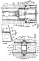
- the wall structure according to the present invention comprises a series of uprights 1, each of which is constituted by two profiled elements 2 made of metal plate which are arranged specularly and are mutually coupled by projection welding.
- Each profiled element 2 has, in cross section, a central portion 3 which is U-shaped so as to compose, together with the other profiled element associated therewith, a square tubular structure.
- each profiled element 2 has two wings 4, each of which can be ideally divided into: a first planar portion 5 for supporting, and joining to, a corresponding first planar portion of the associated profiled element to thereby form the upright 1; a second portion 6, which is orthogonal to the preceding portion and is U-shaped, so as to form a supporting region 7 for a corresponding lateral portion of a curtain-wall panel 8; and a third portion 9 which is slightly inclined with respect to said first planar portion 5 and ends with a curling 10 which defines a sort of bead which is inserted in a snap-together manner, by elastic deformation of said wing 4, into a corresponding longitudinal groove 11 with a rectangular cross section which is provided on the edge of the panel 8.
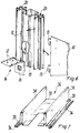
- the second portion 6 is defined so that a certain gap remains between the third portions 9 and the first portions 5 so as to allow access to vertical slots 12 defined on the second portion 6 in a region adjacent to where said second portion bendingly blends with the first portion 5.
- Said slots 12 are suitable for the insertion of hook-shaped ends 13 which extend from laminar supports 14 for shelves or other elements to be applied to the wall.
- said vertical slots 12 are arranged so as to be mutually spaced with a constant pitch.
- a covering strip 15 made of rubber or of an equivalent material.
- brackets 16 which are advantageously provided with holes 17 for fixing by means of screws.
- each bracket 16 In a central region of the vertical portion of each bracket 16 there is instead a tab 18 which is defined by blanking and bending and is suitable for being inserted in an adapted slotted hole 19 of the central portion 3 of the upright 1 and is then caused to slide downward to engage said upright 1.
- the uprights 1 are conveniently secured between the ceiling and the floor without requiring any kind of intervention on such ceiling or floor.
- the second portions 6 of two opposite wings 4 form an insertion seat 20 for a corresponding end of a U-shaped element 21, also made of metal plate, the bottom whereof is transversely inserted in a floor channel 22 constituted by a profiled element made of metal plate and folded so as to be U-shaped with a planar supporting base and vertical wings.
- the floor channel 22 has longitudinal stiffening ridges 23, and its upper ends 24 are curled.
- Said floor channel 22 conveniently rest with its base on elastic elements 25 made of rubber or of another material.
- said U-shaped element 21 has, at the end 24 of the channel 22, folds 25a suitable for constituting supporting regions for it.
- Wings 28 are defined on the base 27, are folded upward and are suitable for keeping the upright 1 in position.
- Said inverted-U element 26 has lateral tabs 29 with folds directed outward so as to define sliding seats for the element 21.
- the lower part of a threaded stem 30 is welded to the base of the element 21, passes through the base 27 of the element 26 and enters the central portion 3 of the upright 1.
- a hexagonal adjustment nut 31 suitable for spacing the bases of the respective elements 21 and 26 or for moving them mutually closer, is screwed on the threaded stem 30 below the base 27 of the element 26.
- a panel supporting profiled element 32 rests on said lateral tabs 29 of the inverted-U sliding element 26;
- said profiled element 32 is composed of a planar central base 33, of two lateral inverted-U portions 34, in which the wings of the floor channel 22 are inserted, of two planar portions 35 which are external to said portions 34 and are co-planar with respect to the base 33 and are suitable for constituting supporting regions for the panels 8, and of two V-shaped end channels 36, each of which is suitable for defining, at its concavity and at its vertex, two engagement regions for respective shaped tabs 37 and 38 which extend laterally from a baseboard 39 made of plastic material.
- a tubular finishing element 40 with a rectangular cross-section is arranged between said baseboard 39 and the floor channel 22.
- the ends of the wings of an inverted-U element 41 are inserted in the upper portions of the seats 20 of the upright 1, and a threaded stem 42 is welded to the base of said element 41 and extends from the center of said base; said stem 42 is inserted, with its other end, between the central portions 3 of said upright 1.
- Said threaded stem 42 passes, in an adapted hole, through a supporting plate 43 which is arranged on the upright 1 and is provided with wings 44 which are folded downward and are suitable for keeping it in position.
- a cylindrical helical spring 45 is located between the base of the element 41 and the supporting plate 43 so as to embrace a portion of the threaded stem 42 and is compressed by a hexagonal nut 46 which is screwed onto the threaded stem 42.
- the structure is completed by a ceiling channel 47 on which the panels 8 rest laterally and on which the inverted-U elements 41 rest internally.
- Elastic elements 48 made of rubber or of another material, are arranged between the channel 47 and the ceiling.
- the presence of the spring is suitable for giving the system a certain elasticity.
- the structure is furthermore composed of a smaller number of parts with respect to current ones and this naturally entails smaller management problems.
- said structure is capable of adapting without trouble also to mounting between non-horizontal ceilings and floors.
- the materials employed may be any according to the requirements.
Landscapes
- Engineering & Computer Science (AREA)
- Architecture (AREA)
- Physics & Mathematics (AREA)
- Electromagnetism (AREA)
- Civil Engineering (AREA)
- Structural Engineering (AREA)
- Buildings Adapted To Withstand Abnormal External Influences (AREA)
- Finishing Walls (AREA)
- Load-Bearing And Curtain Walls (AREA)
- Floor Finish (AREA)
- Panels For Use In Building Construction (AREA)
Claims (16)
- Versetzbare Wandkonstruktion mit einem Rahmen aus vertikalen Stützen (1) und möglichen Querstücken, welche Vorhangwandpaneele (8) tragen, wobei die vertikalen Stützen seitliche Flügel (4) aufweisen, die zur Bildung von Aufliegebereichen (7) für die Paneele (8) geformt sind, welche senkrecht zur Symmetrieachse der vertikalen Stützen (1) verlaufen, wobei jeder Flügel (4) mit einem Bereich (9) endet, der im wesentlichen parallel zu dem Flügel (4) der vertikalen Stütze (1) ist und entlang der Kanten des Paneels (8) verläuft, dadurch gekennzeichnet, daß jeder Flügel (4) eine Eingriffssickenwulst (10) aufweist, welche von dem Bereich (9) hervorsteht und nach Art einer Schnappverbindung durch elastische Deformation des Flügels (4) in eine längsverlaufende Nut (11) der Kante des Paneels (8) eingeführt ist.
- Versetzbare Wandkonstruktion nach Anspruch 1, dadurch gekennzeichnet, daß jede der vertikalen Stützen (1) aus zwei profilierten Elementen (2) besteht, welche aus Metallblech gefertigt sind und einander spiegelbildlich gegenüberstehen, wobei diese profilierten Elemente (2) aus Metallblech durch Warzenschweißungen miteinander verbunden sind.
- Versetzbare Wandkonstruktion nach einem oder mehreren der voranstehenden Ansprüche, dadurch gekennzeichnet, daß jedes profilierte Element (2), welches die vertikale Stütze (1) bildet, einen U-förmigen zentralen Bereich (3) aufweist, um, zusammen mit dem ihm zugeordneten profilierten Element, eine Rohrstruktur rechteckigen Querschnitts zu bilden, wobei das profilierte Element (2) seitlich des zentralen Bereiches (3) zwei Flügel (4) aufweist, von denen jeder besteht aus: einem ersten ebenen Bereich (5) zur Aufnahme und Verbindung mit einem entsprechenden Bereich des anderen profilierten Elements, welches die vertikale Stütze bildet; einem zweiten Bereich (6), welcher senkrecht auf dem voranstehend beschriebenen Bereich steht und die Form eines umgekehrten U hat, um so den Auflagebereich für einen entsprechenden seitlichen Bereich eines Paneels (8) zu bilden; und einem dritten Bereich (9), welcher den zu der Achse der vertikalen Stütze im wesentlichen parallelen Bereich bildet und eine Eingriffssickenwulst (10) aufweist.
- Versetzbare Wandkonstruktion nach einem oder mehreren der voranstehenden Ansprüche, dadurch gekennzeichnet, daß der dritte Bereich (9) jedes Flügels (4) jedes profilierten Elements (2) bezüglich des ersten Bereichs (5) geringfügig geneigt ist und mit der Sickenwulst (10) endet, welche eine Rollsicke bildet, die nach Art einer Schnappverbindung in die längsverlaufende Nut (11) des Paneels (8) eingeführt wird.
- Versetzbare Wandkonstruktion nach einem oder mehreren der voranstehenden Ansprüche, dadurch gekennzeichnet, daß der zweite Bereich (6) jedes Flügels (4) jedes profilierten Elements (2) so ausgeführt wird, daß ein bestimmter Abstand zwischen den dritten Bereichen (9) zweier einander zugeordneter profilierter Elemente verbleibt, wodurch Zugang zu vertikalen Schlitzen (12) auf dem zweiten Bereich (6) jedes Flügels in einer Region ermöglicht wird, welche dem Ort benachbart ist, an dem der zweite Bereich sich gegenüber dem ersten Bereich krümmt, wobei die Schlitze (12) sich zur Einführung hakenförmiger Enden (13) eignen, welche zu Trägern (14) für Regale oder ähnliches gehören.
- Versetzbare Wandkonstruktion nach einem oder mehreren der voranstehenden Ansprüche, dadurch gekennzeichnet, daß der Abstand zwischen den Enden zweier zueinander passender profilierter Elemente (2), soweit er nicht von Trägern (14) für Regale oder ähnliches belegt ist, durch einen Abdeckstreifen (15) aus Gummi oder äquivalentem Material, verschlossen ist.
- Versetzbare Wandkonstruktion nach einem oder mehreren der voranstehenden Ansprüche, dadurch gekennzeichnet, daß die Querstücke so angeordnet sind, daß ihre Enden auf horizontalen Bereichen von Klammern (16) aufliegen, welche mit Bohrungen (17) zur Aneinanderkopplung mit Hilfe von Schrauben versehen sind, wobei jede Klammer in der zentralen Region des vertikalen Bereichs einen herausgetrennten und gekrümmten Streifen (18) aufweist, welcher in ein angepaßtes, geschlitzes Loch (19) des zentralen Bereichs (3) der vertikalen Stütze (1) unter Bildung einer Einführungskupplung mit der unteren Kante dieses Loches einführbar ist.
- Versetzbare Wandkonstruktion nach einem oder mehreren der voranstehenden Ansprüche, dadurch gekennzeichnet, daß Paare der zweiten Bereiche (6) der Flügel (4) der profilierten Elemente (2) jeder vertikalen Stütze (1) entsprechende Sitze (20) zur Einführung der Enden eines U-förmigen Metallblechelements (21) bilden, dessen Unterseite transversal in einen Bodenkanal (22) eingeführt wird.
- Versetzbare Wandkonstruktion nach einem oder mehreren der voranstehenden Ansprüche, dadurch gekennzeichnet, daß der Bodenkanal (22) von einem profilierten Element aus Metallblech gebildet wird, welches U-förmig gebogen ist, mit einer ebenen Trägerbasis und vertikalen Flügeln, welche gerollte obere Enden (24) aufweisen, wobei dieser Bodenkanal vorzugsweise an seiner Basis von Elementen (25) aus Gummi oder äquivalentem Material getragen wird.
- Versetzbare Wandkonstruktion nach einem oder mehreren der voranstehenden Ansprüche, dadurch gekennzeichnet, daß innerhalb des U-förmigen Elements (21), welches transversal in.den Bodenkanal (22) eingeführt wird, ein gleitendes Element (26) in Form eines umgekehrten U auf der Basis (27), auf welcher das untere Ende der entsprechenden vertikalen Stütze (1) aufliegt, angeordnet ist, diese Basis des Elements (26) in Form eines umgekehrten U Flügel (28) aufweist, welche nach oben gebogen sind und die vertikale Stütze (1) in ihrer Position halten können, wobei das Element (26) in Form eines umgekehrten U seitliche Flügel (29) aufweist, welche nach außen gebogen sind, um Gleitsitze für das U-förmige Element (21) zu bilden.
- Versetzbare Wandkonstruktion nach einem oder mehreren der voranstehenden Ansprüche, dadurch gekennzeichnet, daß der untere Teil einer Gewindestange (25) auf der Basis des U-förmigen Elements (21) in dem Bodenkanal (22) angeschweißt ist, diese Gewindestange (25) durch die Basis (27) des Elements (26) in Form eines umgekehrten U verläuft und in den Zentralbereich der entsprechenden vertikalen Stütze (1) verläuft, eine hexagonale Mutter (31) auf der Gewindestange aufgeschraubt ist und an der Basis (27) des Elements (26) in Form eines umgekehrten U anliegt.
- Versetzbare Wandkonstruktion nach einem oder mehreren der voranstehenden Ansprüche, dadurch gekennzeichnet, daß ein Ende eines ein Paneel tragenden profilierten Elements (32) aus Blech auf den seitlichen Flügeln (29) des Elements (26) in Form eines umgekehrten U, auf welchem die vertikale Stütze (1) aufliegt, wobei dieses profilierte Element (32) zusammengesetzt ist aus: einer ebenen zentralen Basis (33); zwei seitlichen Bereichen (34) in Form um-gedrehter U's, in welche die Flügel des Bodenkanals (22) eingeführt sind; zwei ebenen Bereichen (35), welche außerhalb der seitlichen Bereiche (34) in Form umgekehrter U's angeordnet sind, koplanar zu der Basis (33) verlaufen und als Abstützbereiche für die Paneele (8) geeignet sind; und zwei V-förmigen Endkanälen (36).
- Versetzbare Wandkonstruktion nach einem oder mehreren der voranstehenden Ansprüche, dadurch gekennzeichnet, daß jeder der beiden V-förmigen Kanäle (36) im konkaven Bereich und am Vertex zwei Kupplungsbereiche für entsprechend geformte Flügel (37, 38) bilden kann, welche seitlich von einer Grundplatte (39) aus Kunststoff hervorstehen.
- Versetzbare Wandkonstruktion nach einem oder mehreren der voranstehenden Ansprüche, dadurch gekennzeichnet, daß ein rohrförmiges Verblendungselement (40) rechteckigen Querschnitts zwischen der Grundplatte (39) und dem Bodenkanal (22) angeordnet ist.
- Versetzbare Wandkonstruktion nach einem oder mehreren der voranstehenden Ansprüche, dadurch gekennzeichnet, daß die Enden der Flügel eines Elements (41) von umgekehrter U-Form in die oberen Bereiche der Sitze (20) auf den zweiten Bereichen (6) der Flügel (4) der profilierten Elemente (2), welche jede vertikale Stütze (1) bilden, eingeführt sind, eine Gewindestange (42) von der Mitte der Basis des Elements umgekehrter U-Form verläuft, diese Gewindestange (42) daran angeschweißt und, mit ihrem anderen Ende, in den Zentralbereich der vertikalen Stütze (1) eingeführt ist, diese Gewindestange durch ein angepaßtes Loch in der Trägerplatte (43) verläuft, welche an der vertikalen Stütze (1) angebracht ist und mit Flügeln (44) versehen ist, welche nach unten gebogen sind und die Stütze in ihrer Position halten, wobei eine Feder (45) zwischen der Basis des Elements (41) umgekehrter U-Form und der Trägerplatte (43) angeordnet ist, welche durch eine hexagonale Mutter (46), die auf die Gewindestange (42) aufgeschraubt wird, komprimiert wird.
- Wandkonstruktion nach einem oder mehreren der voranstehenden Ansprüche, dadurch gekennzeichnet, daß sie einen Deckenkanal (47) aufweist, auf welchem die Paneele (8) seitlich aufliegen und auf welchem die oberen Elemente (41) umgekehrter U-Form innen aufliegen, sowie elastische Elemente (49), welche aus Gummi oder einem äquivalenten Material bestehen, die zwischen dem Kanal (47) und der Decke angeordnet sind.
Applications Claiming Priority (2)
| Application Number | Priority Date | Filing Date | Title |
|---|---|---|---|
| IT4172890 | 1990-11-12 | ||
| IT04172890A IT1244108B (it) | 1990-11-12 | 1990-11-12 | Struttura di parete mobile |
Publications (2)
| Publication Number | Publication Date |
|---|---|
| EP0485923A1 EP0485923A1 (de) | 1992-05-20 |
| EP0485923B1 true EP0485923B1 (de) | 1996-01-31 |
Family
ID=11253347
Family Applications (1)
| Application Number | Title | Priority Date | Filing Date |
|---|---|---|---|
| EP91119177A Expired - Lifetime EP0485923B1 (de) | 1990-11-12 | 1991-11-11 | Versetzbare Wandkonstruktion |
Country Status (5)
| Country | Link |
|---|---|
| EP (1) | EP0485923B1 (de) |
| AT (1) | ATE133737T1 (de) |
| DE (1) | DE69116802T2 (de) |
| ES (1) | ES2082097T3 (de) |
| IT (1) | IT1244108B (de) |
Families Citing this family (6)
| Publication number | Priority date | Publication date | Assignee | Title |
|---|---|---|---|---|
| DE19833506C1 (de) * | 1998-07-24 | 2000-03-16 | Umdasch Shop Concept Ges M B H | Regalsystem |
| FR2792512B1 (fr) * | 1999-04-23 | 2001-12-28 | Action Dev | Systeme pour l'installation d'etageres avec habillage de la paroi recevant les etageres |
| DE10212978B4 (de) * | 2002-03-19 | 2005-08-04 | Metallbau Ralf Boetker Gmbh | Befestigungseinheit zur höhenjustierbaren Befestigung eines Ausschlussprofils für ein Befestigungs- und/oder Laufschienenprofil an einer Rohdecke und/oder Unterkonstuktion |
| ES2283161B1 (es) * | 2004-02-11 | 2008-09-16 | Aida Ingenieria, S.L. | Biombo. |
| CN112942643B (zh) * | 2021-02-03 | 2022-05-06 | 湖北盈源铝业有限公司 | 一种稳固型铝板幕墙 |
| CN116517167B (zh) * | 2023-07-05 | 2023-09-19 | 中国建筑第五工程局有限公司 | 一种用于绿色建筑工程阴阳角幕墙安装装置 |
Family Cites Families (5)
| Publication number | Priority date | Publication date | Assignee | Title |
|---|---|---|---|---|
| GB685617A (en) * | 1948-11-29 | 1953-01-07 | Martin Parry Corp | Structural element |
| US3312032A (en) * | 1963-07-05 | 1967-04-04 | Ames Taping Tool Systems Mfg C | Metal stud and panel |
| DE1658836A1 (de) * | 1967-09-16 | 1970-11-05 | Franken Dipl Ing Josef | Vorgefertigte Wand |
| DE3225060C2 (de) * | 1982-07-05 | 1984-08-30 | Paul Feederle Möbelfabrik, 7500 Karlsruhe | Regalständer für eine Trennwand oder Wandverkleidung |
| DE3835631A1 (de) * | 1988-10-19 | 1990-05-03 | Holzaepfel Christian Gmbh | Trennwand |
-
1990
- 1990-11-12 IT IT04172890A patent/IT1244108B/it active IP Right Grant
-
1991
- 1991-11-11 AT AT91119177T patent/ATE133737T1/de not_active IP Right Cessation
- 1991-11-11 ES ES91119177T patent/ES2082097T3/es not_active Expired - Lifetime
- 1991-11-11 DE DE69116802T patent/DE69116802T2/de not_active Expired - Lifetime
- 1991-11-11 EP EP91119177A patent/EP0485923B1/de not_active Expired - Lifetime
Also Published As
| Publication number | Publication date |
|---|---|
| DE69116802D1 (de) | 1996-03-14 |
| ES2082097T3 (es) | 1996-03-16 |
| DE69116802T2 (de) | 1996-06-05 |
| IT9041728A1 (it) | 1992-05-12 |
| IT1244108B (it) | 1994-07-05 |
| ATE133737T1 (de) | 1996-02-15 |
| IT9041728A0 (it) | 1990-11-12 |
| EP0485923A1 (de) | 1992-05-20 |
Similar Documents
| Publication | Publication Date | Title |
|---|---|---|
| US4224769A (en) | Space divider system | |
| US4557086A (en) | Grain bin floor support system | |
| US4996811A (en) | Open office system partition panel assembly | |
| RU2272110C2 (ru) | Балка, балочная система и здание, в котором они использованы | |
| US4709517A (en) | Floor-to-ceiling wall system | |
| US5412912A (en) | Modular slatwall assembly | |
| US3228160A (en) | Wall base trim assembly | |
| US4043689A (en) | Modular ceiling system | |
| US6009675A (en) | Knock-down portable partition system | |
| US7143562B2 (en) | Suspension system and structure for securing border ceiling panels | |
| US4761922A (en) | Partition wall construction | |
| EP0146932A2 (de) | Fertigmöbel | |
| CA1325508C (en) | Panel connection arrangement for a partition system | |
| JPH0343557A (ja) | 壁パネル構造 | |
| JPS6237853Y2 (de) | ||
| EP0175569A1 (de) | Verstellbares Regalsystem | |
| JP2005517841A (ja) | パネルシステム | |
| GB2064305A (en) | Improvements in or relating to shelf supports for merchandise display systems | |
| GB2173528A (en) | A grid ceiling | |
| EP0485923A1 (de) | Versetzbare Wandkonstruktion | |
| US3925939A (en) | Support structure for shelving | |
| US4477128A (en) | Partition system storage unit supports | |
| EP0089116A2 (de) | Montage einer Wandplatte | |
| US6286689B1 (en) | Flooring sample holder | |
| US5618017A (en) | Supporting plate unit for ceiling |
Legal Events
| Date | Code | Title | Description |
|---|---|---|---|
| PUAI | Public reference made under article 153(3) epc to a published international application that has entered the european phase |
Free format text: ORIGINAL CODE: 0009012 |
|
| AK | Designated contracting states |
Kind code of ref document: A1 Designated state(s): AT BE CH DE DK ES FR GB GR LI LU NL SE |
|
| 17P | Request for examination filed |
Effective date: 19920923 |
|
| 17Q | First examination report despatched |
Effective date: 19931130 |
|
| GRAA | (expected) grant |
Free format text: ORIGINAL CODE: 0009210 |
|
| AK | Designated contracting states |
Kind code of ref document: B1 Designated state(s): AT BE CH DE DK ES FR GB GR LI LU NL SE |
|
| PG25 | Lapsed in a contracting state [announced via postgrant information from national office to epo] |
Ref country code: BE Effective date: 19960131 Ref country code: DK Effective date: 19960131 Ref country code: AT Effective date: 19960131 Ref country code: CH Effective date: 19960131 Ref country code: GR Free format text: LAPSE BECAUSE OF FAILURE TO SUBMIT A TRANSLATION OF THE DESCRIPTION OR TO PAY THE FEE WITHIN THE PRESCRIBED TIME-LIMIT Effective date: 19960131 Ref country code: LI Effective date: 19960131 Ref country code: NL Free format text: LAPSE BECAUSE OF FAILURE TO SUBMIT A TRANSLATION OF THE DESCRIPTION OR TO PAY THE FEE WITHIN THE PRESCRIBED TIME-LIMIT Effective date: 19960131 |
|
| REF | Corresponds to: |
Ref document number: 133737 Country of ref document: AT Date of ref document: 19960215 Kind code of ref document: T |
|
| ET | Fr: translation filed | ||
| REF | Corresponds to: |
Ref document number: 69116802 Country of ref document: DE Date of ref document: 19960314 |
|
| REG | Reference to a national code |
Ref country code: ES Ref legal event code: FG2A Ref document number: 2082097 Country of ref document: ES Kind code of ref document: T3 |
|
| PG25 | Lapsed in a contracting state [announced via postgrant information from national office to epo] |
Ref country code: SE Effective date: 19960430 |
|
| NLV1 | Nl: lapsed or annulled due to failure to fulfill the requirements of art. 29p and 29m of the patents act | ||
| REG | Reference to a national code |
Ref country code: CH Ref legal event code: PL |
|
| PG25 | Lapsed in a contracting state [announced via postgrant information from national office to epo] |
Ref country code: LU Free format text: LAPSE BECAUSE OF NON-PAYMENT OF DUE FEES Effective date: 19961130 |
|
| PLBE | No opposition filed within time limit |
Free format text: ORIGINAL CODE: 0009261 |
|
| STAA | Information on the status of an ep patent application or granted ep patent |
Free format text: STATUS: NO OPPOSITION FILED WITHIN TIME LIMIT |
|
| 26N | No opposition filed | ||
| REG | Reference to a national code |
Ref country code: GB Ref legal event code: IF02 |
|
| PGFP | Annual fee paid to national office [announced via postgrant information from national office to epo] |
Ref country code: FR Payment date: 20101125 Year of fee payment: 20 |
|
| PGFP | Annual fee paid to national office [announced via postgrant information from national office to epo] |
Ref country code: GB Payment date: 20101119 Year of fee payment: 20 |
|
| PGFP | Annual fee paid to national office [announced via postgrant information from national office to epo] |
Ref country code: DE Payment date: 20110118 Year of fee payment: 20 |
|
| PGFP | Annual fee paid to national office [announced via postgrant information from national office to epo] |
Ref country code: ES Payment date: 20101119 Year of fee payment: 20 |
|
| REG | Reference to a national code |
Ref country code: DE Ref legal event code: R071 Ref document number: 69116802 Country of ref document: DE |
|
| REG | Reference to a national code |
Ref country code: DE Ref legal event code: R071 Ref document number: 69116802 Country of ref document: DE |
|
| REG | Reference to a national code |
Ref country code: GB Ref legal event code: PE20 Expiry date: 20111110 |
|
| PG25 | Lapsed in a contracting state [announced via postgrant information from national office to epo] |
Ref country code: GB Free format text: LAPSE BECAUSE OF EXPIRATION OF PROTECTION Effective date: 20111110 |
|
| PG25 | Lapsed in a contracting state [announced via postgrant information from national office to epo] |
Ref country code: DE Free format text: LAPSE BECAUSE OF EXPIRATION OF PROTECTION Effective date: 20111112 |
|
| REG | Reference to a national code |
Ref country code: ES Ref legal event code: FD2A Effective date: 20130730 |
|
| PG25 | Lapsed in a contracting state [announced via postgrant information from national office to epo] |
Ref country code: ES Free format text: LAPSE BECAUSE OF EXPIRATION OF PROTECTION Effective date: 20111112 |