EP0485974B1 - Système de filtre à particules régénératif pour contrÔle de l'émission - Google Patents
Système de filtre à particules régénératif pour contrÔle de l'émission Download PDFInfo
- Publication number
- EP0485974B1 EP0485974B1 EP91119334A EP91119334A EP0485974B1 EP 0485974 B1 EP0485974 B1 EP 0485974B1 EP 91119334 A EP91119334 A EP 91119334A EP 91119334 A EP91119334 A EP 91119334A EP 0485974 B1 EP0485974 B1 EP 0485974B1
- Authority
- EP
- European Patent Office
- Prior art keywords
- exhaust gas
- particulate trap
- filter
- electric heater
- central portion
- Prior art date
- Legal status (The legal status is an assumption and is not a legal conclusion. Google has not performed a legal analysis and makes no representation as to the accuracy of the status listed.)
- Expired - Lifetime
Links
Images


Classifications
-
- F—MECHANICAL ENGINEERING; LIGHTING; HEATING; WEAPONS; BLASTING
- F01—MACHINES OR ENGINES IN GENERAL; ENGINE PLANTS IN GENERAL; STEAM ENGINES
- F01N—GAS-FLOW SILENCERS OR EXHAUST APPARATUS FOR MACHINES OR ENGINES IN GENERAL; GAS-FLOW SILENCERS OR EXHAUST APPARATUS FOR INTERNAL-COMBUSTION ENGINES
- F01N3/00—Exhaust or silencing apparatus having means for purifying, rendering innocuous, or otherwise treating exhaust
- F01N3/02—Exhaust or silencing apparatus having means for purifying, rendering innocuous, or otherwise treating exhaust for cooling, or for removing solid constituents of, exhaust
- F01N3/021—Exhaust or silencing apparatus having means for purifying, rendering innocuous, or otherwise treating exhaust for cooling, or for removing solid constituents of, exhaust by means of filters
- F01N3/023—Exhaust or silencing apparatus having means for purifying, rendering innocuous, or otherwise treating exhaust for cooling, or for removing solid constituents of, exhaust by means of filters using means for regenerating the filters, e.g. by burning trapped particles
- F01N3/027—Exhaust or silencing apparatus having means for purifying, rendering innocuous, or otherwise treating exhaust for cooling, or for removing solid constituents of, exhaust by means of filters using means for regenerating the filters, e.g. by burning trapped particles using electric or magnetic heating means
-
- Y—GENERAL TAGGING OF NEW TECHNOLOGICAL DEVELOPMENTS; GENERAL TAGGING OF CROSS-SECTIONAL TECHNOLOGIES SPANNING OVER SEVERAL SECTIONS OF THE IPC; TECHNICAL SUBJECTS COVERED BY FORMER USPC CROSS-REFERENCE ART COLLECTIONS [XRACs] AND DIGESTS
- Y10—TECHNICAL SUBJECTS COVERED BY FORMER USPC
- Y10S—TECHNICAL SUBJECTS COVERED BY FORMER USPC CROSS-REFERENCE ART COLLECTIONS [XRACs] AND DIGESTS
- Y10S55/00—Gas separation
- Y10S55/30—Exhaust treatment
Definitions
- the present invention relates to an exhaust gas purification system for trapping carbon and other particulates in an exhaust gas of a diesel engine. More particularly, the invention relates to a particulate trap system for an exhaust gas, by which a filter for trapping particulates, such as a ceramic filter, can be regenerated.
- an exhaust gas purification system or an emission control system is provided for trapping particulates, such as carbon particles and so forth, as an anti-pollution measure.
- a carbon particulates cleaning device wherein carbon particulates contained in exhaust gases of an internal combustion engine are collected and burnt off by use of an electric heater provided on the upstream end surface of a heat resistant filter member.
- the electric heater comprises a plurality of heating resistors, to which current is supplied successively in an order depending on a power density thereof. In this manner, the burning of particulates is distributed in time to respective heating areas, thereby varying the exhaust gas flow through the respective heating areas and the cooling effect involved therein.
- FIG. 7 A further example of an exhaust gas purification system is illustrated in Fig. 7.
- a particulate trap system 14 is connected to an exhaust pipe 12 of a diesel engine 10, and a particulate trap filter 16 is disposed inside the particulate trap system 14.
- the particulate trap filter 16 is formed as a porous ceramic cylinder having a honeycomb structure, and defines a plurality of upstream side passages 16a and downstream side passages 16b separated by porous partitions 18, as shown in Fig. 8.
- the downstream ends and the upstream ends of the upstream side passages 16a, and the downstream side passages 16b, are closed respectively, and accordingly, the exhaust gas from the diesel engine 10 flows into the purification system 14 through upstream side open ends of the upstream side passages 16a.
- the gaseous component of the exhaust gas then passes through the porous structure of the porous partitions 18 into the adjacent downstream side passages 16b, and is then subsequently discharged.
- the particulates, such as carbon particles, contained in the exhaust gas are blocked by the partition 18, and thus are trapped and accumulated in the upstream side passages 16a.
- an increase of the amount of accumulated particulates causes an increase in the resistance to the exhaust gas flow, to thus increase the pressure difference ⁇ p between the upstream end and the downstream end of the particulate trap filter 16, which may lower the output of the engine 10. Therefore, it is necessary to periodically remove the accumulated particulates, and accordingly, an electronic heater 20 is provided on the upstream side wall surface, for heating and burning the trapped particulates, to thereby regenerate the particulate trap filter.
- Figs. 7 and 8 22 denotes a filter casing forming the outer shell of the purification system 14, 24 denotes a bypass passage for allowing the exhaust gas to bypass the purification system 14, and 26 denotes a bypass valve for selectively switching the exhaust gas flow path.
- Figure 9 shows local temperature variations during the regeneration treatment, to represent the above-mentioned condition of remaining unburnt particulate.
- the solid line shows temperature variations according to a processing time at the center portion A of the particulate trap filter 16 (for example, in the region A in Fig. 8), and the broken line shows temperature variations according to the processing time at the outer circumferential portion B away from the center (for example, at the region B in Fig. 8). Due to the increase in the difference (temperature difference ⁇ T1) between the peak values of the two curves, the amount of unburnt particulates at the outer circumferential portion B is increased. Also, when the temperature at the central portion A of the filter 16 becomes much higher than that at the outer circumferential portion B, the filter may be destroyed by a substantial thermal distortion thereof.
- an object of the present invention is to provide a regenerative particulate trap system for an exhaust gas, by which the above-mentioned problems in the prior art are solved and an effective regeneration over the whole area of a particulate trap filter is obtained by preventing an incomplete regeneration due to the outer circumferential portion thereof.
- Another object of the present invention is to reduce the temperature gradient between the center portion and the outer circumferential portion of the particulate trap filter, and thus prevent a destruction of the filter due to an excessive thermal distortion thereof.
- a further object of the present invention is to reduce the electric power consumed by an electric heater used for the regeneration of the particulate trap filter, to thus reduce the load on a power source such as a battery.
- a particulate trap system for an exhaust emission control comprising a particulate trap filter disposed within a path for the exhaust gas of an engine for trapping particulates carried by the exhaust gas of the engine; and an electric heater arranged at an upstream end surface of said particulate trap filter for removing accumulated particulates by burning same; characterized in that in a particulate trap filter having a circular end face said electric heater is arranged in a predetermined pattern such that a power efficiency provided for an outer circumferential portion off a central position and peripheral to a central portion of said particulate trap filter is higher than the power efficiency provided for said central portion, or in a particulate trap filter having an oval or elliptic end face said electric heater is arranged in a predetermined pattern such that a higher power efficiency is provided at both end portions of the longer axes than at the central portion.
- the particulate trap system for an exhaust gas includes an electric heater for burning particulates accumulated in a particulate trap filter.
- the electric heater is arranged in such a manner that it provides a higher power efficiency at a portion away from the center of the trap filter relative to that at a portion close to the center.
- the portion of the electric heater having a higher power efficiency includes sections of heating wire buried in plugs, for defining the exhaust gas flow path, and the portion of the electric heater having the lower power efficiency includes sections of the heating wire which are bent and inserted to the inlet portion of the exhaust gas flow path.
- the particulate trap filter may have a circular end face, in which the portion of the filter located away from the center and having the portion of the electric heater providing a higher power efficiency, and the portion of the filter located at the center and having the portion of the electric heater providing a lower power efficiency are arranged in an essentially concentric manner.
- the particulate trap filter may have an oval or elliptic end face configuration, in which the portion of the filter having portions of the electric heater providing a higher power efficiency are located at both ends along the longer axis of the filter, and the portion of the filter having the portion of the electric heater providing a lower power efficiency is located therebetween.
- the particulate trap filter may be provided with a higher particulate trapping efficiency at the portion away from the center, and a lower particulate trapping efficiency at the central position, by rarying the patterns used for closing the passage by the plug.
- the electric heater in a pattern as set forth hereinafter, a greater heat energy can be provided at the outer peripheral portion, from which the heat can easily escape, to ensure and maintain the burning of the particulates,to thereby fully regenerate the filter.
- the central portion can maintain the heat and does therefore not require a large heat capacity to maintain the burning of the particulates, so that the amount of heat generated is limited by providing a lower power efficiency to thus reduce the power consumption and to prevent overheating.
- Figs. 1 and 2 show the first embodiment of a particulate trap system for an exhaust gas according to the present invention.
- a particulate trap filter 16 having a circular cross-section is employed, and an electric heater 20 is provided on the upstream end face C of the filter 16.
- the density of the heating wires of the electric heater 20 is different at different portions of the filter 16, to thereby differentiate the amount of electric power consumed in each unit area.
- a higher density of the heating wires 20B is provided in an outer circumferential portion B defined concentrically to a central portion A, than the density of the heating wires 20A in the central portion.
- the power efficiency at the outer circumferential portion B is higher than that in the central portion A.
- portions 20B' of the heating wire 20B are buried in upstream side plugs 28 used to plug downstream side passages defined in the filter 16, to provide a higher density.
- the heating wire 20A is fitted along the end face C of the filter 16. Since the heating wire 20A covers a wider area than that of an equivalent length of the heating wire 20B, the power consumed (equivalent to the amount of heat generated) at the unit area of the end face of the filter C is reduced.
- the heating wire 20A is provided with V-shaped bent sections 20A' which are engaged with the opening end of upstream side passages, for positioning and fixing the heating wire 20A on the end face of the filter 16.
- bent sections 20A' are provided at the turning portions (portions 20A" in Fig. 1) by bending the turning portions at a right angle and bending the angled corner into the corresponding opening ends.
- a heat resistive inorganic bonding material can be filled in the passage to bond the bent sections 20A'.
- the upstream side passages to which the bond is filled will be blocked and will not function as a filter. Nevertheless, as can be appreciated, because of the large number of upstream side passages formed in the filter 16, the blocking of some of the passages will not affect the exhaust gas flow or the filtering function of the filter overall .
- the pitch of the wiring pattern must be wider than that of the heating wire 20B to provide a lower power efficiency.
- the wiring pattern will become as illustrated in Fig. 3.
- the wiring pattern shown in Fig. 3 is not preferable. Namely, the wiring pattern of the heating wire 20A must be carefully arranged.
- Fig. 3 Although the construction shown in Fig. 3 is not preferred due to the possibility of remaining unburnt particulates during the regeneration process, an equivalent construction may be applied without causing the defects set out with respect to Fig. 3, when the depth to which the heating wire 20A is buried is different from that of the heating wire 20B to thus achieve the desired difference in the power efficiency.
- the burying depth of the heating wire 20A at the central portion A must be much less than that of the heating wire 20B in the outer circumferential portion B. Namely, by differentiating the burying depth, the desired difference of the power efficiency can be obtained without changing the pitch of the wiring pattern.
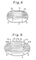
- Figures 4 and 5 show second and third embodiments of the invention respectively.
- the cross-sectional configuration of the system be an oval or elliptic cross section, for an easier mounting thereof.
- the cooling effect is poor even at the outer circumferential portions.
- the cooling effect is substantial not only at the outer circumferential portions but also at the portion near the central position, to possibly cause a remaining of unburnt particulates.
- the heating wires 20A and 20B are arranged in a pattern such that a higher power efficiency is provided at both end portions B of the longer axes than that at the central portion A.
- a wiring pattern With such a wiring pattern, the problem of unburnt particulates at the end portions B of the longer axes does not arise.
- the temperature gradient between the portions A and B can be reduced, to prevent a destruction of the filter due to a substantial thermal distortion thereof.
- the heating wire 20A in the central portion A must extend across the outer circumferential portion B, and thus an intervention between the heating wires 20A and 20B, such as an insulation, is required.
- the lead wires 30 and 32 can be directly extracted, the wiring is simplified.
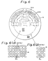
- Figure 6 shows the fourth embodiment of the particulate trap system according to the present invention, in which the plugging pattern for determining the arrangement of the upstream side passages 16a opening toward the upstream and the downstream side passages 16b opening toward the downstream is different at the central portion A and the outer circumferential portion B, to thus provide different particulate trapping performances therebetween.
- the patterns of the heating wires are adapted to the plugging pattern.
- the plugs 28 are provided for every other passage as shown in Fig. 6(b), for arranging the upstream side passages 16a and the downstream side passages 16b.
- the plugs 28 are provided for every four passages as shown in Fig. 6(a), to reduce the surface area of the porous partition 18 used for trapping the particulate. Also, to ensure a complete burning of the large amount of particulates collected in the outer circumferential portion B, a higher density of the heating wire 20B is arranged as shown in Fig. 6, and the heating wires 20A are arranged in the central portion A at the lower density. Such an arrangement of the heating wires enables a good combustibility and propagation of the combustion to be obtained.
- the present invention can be applied to any particulate trapping filter 16, such as a known ceramic foam filter, a filter composed of steel wool coated by a porous alumina layer, or the like.
Landscapes
- Engineering & Computer Science (AREA)
- Chemical & Material Sciences (AREA)
- Combustion & Propulsion (AREA)
- Mechanical Engineering (AREA)
- General Engineering & Computer Science (AREA)
- Processes For Solid Components From Exhaust (AREA)
Claims (7)
- Système de piégeage de particules pour un dispositif de contrôle d'émission d'échappement, comprenant :un filtre de piégeage de particules (16) disposé à l'intérieur d'un trajet (12) pour les gaz d'échappement d'un moteur (10) pour piéger les particules transportées par les gaz d'échappement du moteur ; etun élément chauffant électrique (20) disposé au niveau d'une surface d'extrémité amont dudit filtre de piégeage de particules (16) pour retirer les particules accumulées en brûlant celles-ci ;caractérisé en ce que :dans un filtre de piégeage de particules (16) ayant une face d'extrémité circulaire, ledit élément chauffant électrique (20) est configuré selon un motif prédéterminé, de telle sorte que le rendement en énergie d'une partie circonférencielle extérieure (B), située à l'extérieur de la position centrale d'une partie centrale (A) dudit filtre de piégeage de particules (16) et en périphérie de celle-ci, soit supérieur au rendement en énergie de ladite partie centrale (A), ou en ce quedans un filtre de piégeage de particules (16) ayant une face d'extrémité ovale ou elliptique, ledit élément chauffant électrique (20) est configuré selon un motif prédéterminé, de telle sortie que l'on obtienne au niveau des deux parties d'extrémité (B) des axes de la longueur un rendement en énergie plus élevé qu'au niveau de la partie centrale (A).
- Système de piégeage de particules pour gaz d'échappement selon la revendication 1, caractérisé en ce qu'une partie (20B) dudit élément chauffant électrique (20) ayant le rendement en énergie le plus élevé comprend des sections (20B') du fil chauffant qui sont noyées dans des bouchons (28) définissant le trajet d'écoulement (16a, 16b) des gaz d'échappement, et en ce qu'une partie (20A) de l'élément chauffant électrique (20) ayant le rendement en énergie le moins élevé comprend des sections (20A') du fil chauffant qui sont pliées et insérées dans la partie d'entrée du trajet d'écoulement (16a) des gaz d'échappement.
- Système de piégeage de particules pour gaz d'échappement selon la revendication 2, caractérisé en ce que ledit filtre de piégeage de particules (16) comprend différentes configurations de fermeture de passage de gaz d'échappement constituées par lesdits bouchons (28) et configurées de façon à obtenir de meilleures performances de piégeage des particules au niveau de ladite partie (B) extérieure à ladite partie centrale (A) et de moins bonnes performances de piégeage des particules au niveau de ladite partie centrale (A).
- Système de piégeage de particules pour gaz d'échappement selon la revendication 1, caractérisé en ce que, dans ledit filtre de piégeage de particules (16) ayant ladite face d'extrémité circulaire, ladite partie circonférencielle extérieure (B) ayant le rendement en énergie le plus élevé et ladite partie centrale (A) ayant le rendement en énergie le moins élevé sont configurées d'une façon essentiellement concentrique.
- Système de piégeage de particules selon l'une quelconque des revendications 1 à 4 précédentes, caractérisé en ce que ledit filtre de piégeage de particules (16) comprend :une pluralité de cloisons poreuses (18) disposées dans ledit trajet (12) pour les gaz d'échappement dudit moteur (10), qui transporte des particules, lesdites cloisons (18) définissant une pluralité de passages de gaz d'échappement (16a, 16b) destinés au passage des gaz d'échappement à travers ceux-ci ;des premiers moyens formant bouchon (28) pour fermer de façon sélective une première extrémité desdits passages de gaz d'échappement (16b) définis par lesdites cloisons (18) ;des deuxièmes moyens formant bouchon (28) pour fermer sélectivement les autres extrémités desdits passages de gaz d'échappement (16a) qui sont maintenus ouverts auxdites premières extrémités, de façon à former un trajet de gaz d'échappement à travers lesdites cloisons poreuses (18) afin de piéger lesdites particules transportées par les gaz d'échappement dans lesdites cloisons poreuses (18) ; et en ce queledit élément chauffant électrique (20) comprend des parties noyées dans lesdits premiers moyens formant bouchon (28) de façon à être fixées sur lesdites premières extrémités desdits passages de gaz d'échappement pour chauffer et brûler les particules accumulées dans lesdits passages de gaz d'échappement, les profondeurs auxquelles sont noyées lesdites parties dudit élément chauffant électrique (20) étant plus grandes au niveau de ladite partie (B) du filtre qui est extérieure au centre de celui-ci qu'au niveau de ladite partie centrale (A).
- Système de piégeage de particules selon la revendication 5, caractérisé en ce que, dans ledit filtre de piégeage de particules (16) ayant ladite forme de face d'extrémité ovale ou elliptique, ladite partie dudit élément chauffant électrique (20) noyée à une plus grande profondeur est disposée aux deux extrémités du grand axe dudit filtre.
- Système de piégeage de particules selon la revendication 5, caractérisé en ce que ledit élément chauffant électrique (20) engendre une capacité thermique qui est plus grande au niveau de ladite partie circonférencielle extérieure (B), qui est extérieure à la partie centrale (A), qu'au niveau de ladite partie centrale (A).
Applications Claiming Priority (2)
| Application Number | Priority Date | Filing Date | Title |
|---|---|---|---|
| JP2306084A JPH04179818A (ja) | 1990-11-14 | 1990-11-14 | 排気ガス微粒子浄化装置 |
| JP306084/90 | 1990-11-14 |
Publications (2)
| Publication Number | Publication Date |
|---|---|
| EP0485974A1 EP0485974A1 (fr) | 1992-05-20 |
| EP0485974B1 true EP0485974B1 (fr) | 1996-01-24 |
Family
ID=17952840
Family Applications (1)
| Application Number | Title | Priority Date | Filing Date |
|---|---|---|---|
| EP91119334A Expired - Lifetime EP0485974B1 (fr) | 1990-11-14 | 1991-11-13 | Système de filtre à particules régénératif pour contrÔle de l'émission |
Country Status (4)
| Country | Link |
|---|---|
| US (1) | US5144798A (fr) |
| EP (1) | EP0485974B1 (fr) |
| JP (1) | JPH04179818A (fr) |
| DE (1) | DE69116644T2 (fr) |
Families Citing this family (38)
| Publication number | Priority date | Publication date | Assignee | Title |
|---|---|---|---|---|
| DE4132439A1 (de) * | 1991-09-28 | 1993-04-01 | Behr Gmbh & Co | Abgaskatalysator |
| DE4209213A1 (de) * | 1992-03-21 | 1993-09-23 | Fev Motorentech Gmbh & Co Kg | Filteranordnung zum entfernen von russpartikeln aus abgasen einer verbrennungskraftmaschine |
| US5655212A (en) * | 1993-03-12 | 1997-08-05 | Micropyretics Heaters International, Inc. | Porous membranes |
| DE69423857T2 (de) * | 1993-12-17 | 2000-11-09 | Matsushita Electric Industrial Co., Ltd. | Verfahren und Vorrichtung zur Reinigung von Abgas |
| WO1995027843A1 (fr) * | 1994-04-06 | 1995-10-19 | Minnesota Mining And Manufacturing Company | Cartouche pour filtre avec un filtre a particules destinee a un moteur diesel et se pretant a une regeneration electrique |
| CA2219542A1 (fr) * | 1996-10-22 | 1998-04-22 | Sumitomo Electric Industries, Ltd. | Element chauffant de regeneration pour filtre de particules emises par un moteur diesel et filtre de ce type utilisant cet element chauffant |
| DE10029978A1 (de) | 2000-06-26 | 2002-01-10 | Zeuna Staerker Kg | Vorrichtung zur Nachbehandlung von Dieselabgasen |
| DE10105233A1 (de) * | 2001-02-02 | 2002-08-29 | Zeuna Staerker Kg | Vorrichtung zur Nachbehandlung von Dieselabgasen |
| DE10106769A1 (de) * | 2001-02-12 | 2002-08-14 | Ego Elektro Geraetebau Gmbh | Abgasfilter mit einer elektrischen Heizeinrichtung und Verfahren zum Abbrennen von Ruß in einem Abgasfilter |
| DE50202490D1 (de) | 2001-06-18 | 2005-04-21 | Hjs Fahrzeugtechnik Gmbh & Co | Mit russabbrennung arbeitender partikelfilter für dieselmotoren |
| DE10151425A1 (de) * | 2001-10-18 | 2003-04-30 | Opel Adam Ag | Partikelfilter zum Reinigen von motorischen Abgasen |
| US7238217B2 (en) * | 2004-04-23 | 2007-07-03 | Corning Incorporated | Diesel engine exhaust filters |
| US20090278595A1 (en) * | 2005-07-14 | 2009-11-12 | Braithwaite Sherman W | Braithwaite particle trap (THE BPT) |
| US20080163615A1 (en) * | 2007-01-04 | 2008-07-10 | Trimingham Scott R | Internal combustion engine exhaust filter with pressure relief |
| US7862635B2 (en) * | 2007-02-12 | 2011-01-04 | Gm Global Technology Operations, Inc. | Shielded regeneration heating element for a particulate filter |
| US7931715B2 (en) * | 2007-02-12 | 2011-04-26 | Gm Global Technology Operations, Inc. | DPF heater attachment mechanisms |
| US8388741B2 (en) * | 2007-08-14 | 2013-03-05 | GM Global Technology Operations LLC | Electrically heated particulate filter with reduced stress |
| CN101429888B (zh) * | 2007-08-31 | 2013-03-27 | 通用汽车环球科技运作公司 | 设置为与微粒过滤器成间隔关系的分区电加热器 |
| US8057581B2 (en) * | 2007-08-31 | 2011-11-15 | GM Global Technology Operations LLC | Zoned electrical heater arranged in spaced relationship from particulate filter |
| US8112990B2 (en) * | 2007-09-14 | 2012-02-14 | GM Global Technology Operations LLC | Low exhaust temperature electrically heated particulate matter filter system |
| US7981198B2 (en) * | 2007-09-14 | 2011-07-19 | GM Global Technology Operations LLC | Overlap zoned electrically heated particulate filter |
| US9140159B2 (en) * | 2007-09-18 | 2015-09-22 | Eugene V. Gonze | High exhaust temperature, zoned, electrically-heated particulate matter filter |
| DE102008050019B4 (de) | 2007-10-04 | 2020-07-09 | GM Global Technology Operations LLC (n. d. Ges. d. Staates Delaware) | System und Verfahren zur variablen Leistungsverteilung für zonenweise Regeneration eines elektrisch beheizten Partikelfilters |
| US8146350B2 (en) * | 2007-10-04 | 2012-04-03 | GM Global Technology Operations LLC | Variable power distribution for zoned regeneration of an electrically heated particulate filter |
| US20100095657A1 (en) * | 2008-10-21 | 2010-04-22 | Gm Global Technology Operations, Inc. | Electrically heated diesel particulate filter (dpf) |
| US8584445B2 (en) * | 2009-02-04 | 2013-11-19 | GM Global Technology Operations LLC | Method and system for controlling an electrically heated particulate filter |
| US8950177B2 (en) * | 2009-06-17 | 2015-02-10 | GM Global Technology Operations LLC | Detecting particulate matter load density within a particulate filter |
| US8341945B2 (en) * | 2009-07-01 | 2013-01-01 | GM Global Technology Operations LLC | Electrically heated particulate filter |
| US8443590B2 (en) * | 2009-07-02 | 2013-05-21 | GM Global Technology Operations LLC | Reduced volume electrically heated particulate filter |
| US8479496B2 (en) * | 2009-07-02 | 2013-07-09 | GM Global Technology Operations LLC | Selective catalytic reduction system using electrically heated catalyst |
| US8475574B2 (en) * | 2009-08-05 | 2013-07-02 | GM Global Technology Operations LLC | Electric heater and control system and method for electrically heated particulate filters |
| US8511069B2 (en) * | 2009-08-12 | 2013-08-20 | GM Global Technology Operations LLC | Systems and methods for layered regeneration of a particulate matter filter |
| US8707684B2 (en) * | 2010-11-11 | 2014-04-29 | GM Global Technology Operations LLC | Control method and apparatus for regenerating a particulate filter |
| US8505284B2 (en) * | 2011-07-26 | 2013-08-13 | GM Global Technology Operations LLC | Stratified particulate filter regeneration system |
| US8726642B2 (en) * | 2011-11-22 | 2014-05-20 | GM Global Technology Operations LLC | Electrically heated particulate filter restrike methods and systems |
| US10087799B2 (en) * | 2015-07-01 | 2018-10-02 | Denso International America, Inc. | Exhaust device and method of manufacturing an exhaust device with a thermally enhanced substrate |
| FR3094039B1 (fr) | 2019-03-21 | 2021-03-19 | Faurecia Systemes Dechappement | Organe de chauffage durable pour dispositif de purification des gaz d’échappement d’un véhicule |
| US20210301702A1 (en) | 2020-03-31 | 2021-09-30 | Johnson Matthey Public Limited Company | Exhaust gas joule heater |
Family Cites Families (9)
| Publication number | Priority date | Publication date | Assignee | Title |
|---|---|---|---|---|
| US4373330A (en) * | 1981-06-29 | 1983-02-15 | General Motors Corporation | Diesel engine dual path exhaust cleaner and burner system |
| JPS58106115A (ja) * | 1981-12-17 | 1983-06-24 | Nippon Soken Inc | 電気的加熱手段を有する排気ガス微粒子浄化装置 |
| JPS58124012A (ja) * | 1982-01-19 | 1983-07-23 | Toyota Motor Corp | 排気パテイキユレ−トトラツプ |
| US4512786A (en) * | 1982-04-21 | 1985-04-23 | Mazda Motor Corporation | Exhaust gas purifying device |
| JPS58210310A (ja) * | 1982-06-01 | 1983-12-07 | Nippon Denso Co Ltd | 内燃機関のカ−ボン微粒子浄化装置 |
| JPS5990713A (ja) * | 1982-11-17 | 1984-05-25 | Toyota Motor Corp | デイ−ゼルエンジンの微粒子浄化装置 |
| JPS6038018A (ja) * | 1983-08-09 | 1985-02-27 | Kazuo Ishii | 多重多孔面濾過器 |
| JPS60125715A (ja) * | 1983-12-09 | 1985-07-05 | Toyota Motor Corp | ディ−ゼル機関の排気処理方法 |
| DE3712333A1 (de) * | 1987-04-11 | 1988-10-20 | Fev Motorentech Gmbh & Co Kg | Regenerierbare filteranordnung zum entfernen von russpartikeln aus abgasen |
-
1990
- 1990-11-14 JP JP2306084A patent/JPH04179818A/ja active Pending
-
1991
- 1991-11-13 DE DE69116644T patent/DE69116644T2/de not_active Expired - Fee Related
- 1991-11-13 US US07/792,200 patent/US5144798A/en not_active Expired - Fee Related
- 1991-11-13 EP EP91119334A patent/EP0485974B1/fr not_active Expired - Lifetime
Also Published As
| Publication number | Publication date |
|---|---|
| EP0485974A1 (fr) | 1992-05-20 |
| US5144798A (en) | 1992-09-08 |
| JPH04179818A (ja) | 1992-06-26 |
| DE69116644D1 (de) | 1996-03-07 |
| DE69116644T2 (de) | 1996-06-05 |
Similar Documents
| Publication | Publication Date | Title |
|---|---|---|
| EP0485974B1 (fr) | Système de filtre à particules régénératif pour contrÔle de l'émission | |
| EP1450015B1 (fr) | Filtre en nid d'abeilles et système de purification des gaz d'échappement | |
| EP0990777B1 (fr) | Système de régénération pour dispositif d'épuration de gaz d'échappement | |
| US4548625A (en) | Exhaust gas cleaning device for diesel engines | |
| JPH0368210B2 (fr) | ||
| JP2707049B2 (ja) | ディーゼルパティキュレートフィルタ | |
| JPS58199018A (ja) | 電気的加熱手段を有する排気ガス微粒子浄化装置 | |
| JPS62225221A (ja) | パテイキユレ−トトラツプ | |
| JPH10121941A (ja) | 排気ガス浄化装置 | |
| JP3147356B2 (ja) | 排気ガス微粒子浄化装置 | |
| EP0879938B1 (fr) | Dispositif de purification des gaz d'échappement d'un moteur à combustion interne | |
| JPH0115684B2 (fr) | ||
| JP3067365B2 (ja) | 内燃機関の排気浄化装置 | |
| JP3401946B2 (ja) | 内燃機関の排気微粒子処理装置 | |
| JPH06241022A (ja) | 排気浄化装置 | |
| JP3064322B2 (ja) | 内燃機関の排気浄化装置 | |
| JPH07189657A (ja) | 内燃機関の排気微粒子捕集フィルタ | |
| JPH0634570Y2 (ja) | 内燃機関の排気浄化装置 | |
| JPH06264722A (ja) | フィルタ装置 | |
| JPH0430329Y2 (fr) | ||
| JP2722854B2 (ja) | 内燃機関の排気フィルタ | |
| JPH0322504Y2 (fr) | ||
| JPH04298625A (ja) | 内燃機関用フィルタ再生装置 | |
| JPH0741859Y2 (ja) | 内燃機関の排気浄化装置 | |
| JPH11132027A (ja) | 内燃機関の排気微粒子浄化システム |
Legal Events
| Date | Code | Title | Description |
|---|---|---|---|
| PUAI | Public reference made under article 153(3) epc to a published international application that has entered the european phase |
Free format text: ORIGINAL CODE: 0009012 |
|
| AK | Designated contracting states |
Kind code of ref document: A1 Designated state(s): DE FR GB |
|
| 17P | Request for examination filed |
Effective date: 19920717 |
|
| 17Q | First examination report despatched |
Effective date: 19930804 |
|
| GRAA | (expected) grant |
Free format text: ORIGINAL CODE: 0009210 |
|
| AK | Designated contracting states |
Kind code of ref document: B1 Designated state(s): DE FR GB |
|
| REF | Corresponds to: |
Ref document number: 69116644 Country of ref document: DE Date of ref document: 19960307 |
|
| ET | Fr: translation filed | ||
| PGFP | Annual fee paid to national office [announced via postgrant information from national office to epo] |
Ref country code: GB Payment date: 19961104 Year of fee payment: 6 |
|
| PGFP | Annual fee paid to national office [announced via postgrant information from national office to epo] |
Ref country code: FR Payment date: 19961111 Year of fee payment: 6 |
|
| PGFP | Annual fee paid to national office [announced via postgrant information from national office to epo] |
Ref country code: DE Payment date: 19961122 Year of fee payment: 6 |
|
| PLBE | No opposition filed within time limit |
Free format text: ORIGINAL CODE: 0009261 |
|
| STAA | Information on the status of an ep patent application or granted ep patent |
Free format text: STATUS: NO OPPOSITION FILED WITHIN TIME LIMIT |
|
| 26N | No opposition filed | ||
| REG | Reference to a national code |
Ref country code: GB Ref legal event code: 746 Effective date: 19970901 |
|
| PG25 | Lapsed in a contracting state [announced via postgrant information from national office to epo] |
Ref country code: GB Free format text: LAPSE BECAUSE OF NON-PAYMENT OF DUE FEES Effective date: 19971113 |
|
| PG25 | Lapsed in a contracting state [announced via postgrant information from national office to epo] |
Ref country code: FR Free format text: THE PATENT HAS BEEN ANNULLED BY A DECISION OF A NATIONAL AUTHORITY Effective date: 19971130 |
|
| GBPC | Gb: european patent ceased through non-payment of renewal fee |
Effective date: 19971113 |
|
| PG25 | Lapsed in a contracting state [announced via postgrant information from national office to epo] |
Ref country code: DE Free format text: LAPSE BECAUSE OF NON-PAYMENT OF DUE FEES Effective date: 19980801 |
|
| REG | Reference to a national code |
Ref country code: FR Ref legal event code: ST |