EP0486157A2 - Perfectionnements aux fils de guidage et cathéters utilisables avec ceux-ci - Google Patents
Perfectionnements aux fils de guidage et cathéters utilisables avec ceux-ci Download PDFInfo
- Publication number
- EP0486157A2 EP0486157A2 EP91309440A EP91309440A EP0486157A2 EP 0486157 A2 EP0486157 A2 EP 0486157A2 EP 91309440 A EP91309440 A EP 91309440A EP 91309440 A EP91309440 A EP 91309440A EP 0486157 A2 EP0486157 A2 EP 0486157A2
- Authority
- EP
- European Patent Office
- Prior art keywords
- guidewire
- catheter
- distal end
- lumen
- shaft
- Prior art date
- Legal status (The legal status is an assumption and is not a legal conclusion. Google has not performed a legal analysis and makes no representation as to the accuracy of the status listed.)
- Withdrawn
Links
Images



Classifications
-
- A—HUMAN NECESSITIES
- A61—MEDICAL OR VETERINARY SCIENCE; HYGIENE
- A61M—DEVICES FOR INTRODUCING MEDIA INTO, OR ONTO, THE BODY; DEVICES FOR TRANSDUCING BODY MEDIA OR FOR TAKING MEDIA FROM THE BODY; DEVICES FOR PRODUCING OR ENDING SLEEP OR STUPOR
- A61M25/00—Catheters; Hollow probes
- A61M25/01—Introducing, guiding, advancing, emplacing or holding catheters
- A61M25/09—Guide wires
-
- A—HUMAN NECESSITIES
- A61—MEDICAL OR VETERINARY SCIENCE; HYGIENE
- A61M—DEVICES FOR INTRODUCING MEDIA INTO, OR ONTO, THE BODY; DEVICES FOR TRANSDUCING BODY MEDIA OR FOR TAKING MEDIA FROM THE BODY; DEVICES FOR PRODUCING OR ENDING SLEEP OR STUPOR
- A61M25/00—Catheters; Hollow probes
- A61M25/01—Introducing, guiding, advancing, emplacing or holding catheters
- A61M25/09—Guide wires
- A61M2025/09058—Basic structures of guide wires
- A61M2025/09083—Basic structures of guide wires having a coil around a core
-
- A—HUMAN NECESSITIES
- A61—MEDICAL OR VETERINARY SCIENCE; HYGIENE
- A61M—DEVICES FOR INTRODUCING MEDIA INTO, OR ONTO, THE BODY; DEVICES FOR TRANSDUCING BODY MEDIA OR FOR TAKING MEDIA FROM THE BODY; DEVICES FOR PRODUCING OR ENDING SLEEP OR STUPOR
- A61M25/00—Catheters; Hollow probes
- A61M25/01—Introducing, guiding, advancing, emplacing or holding catheters
- A61M25/09—Guide wires
- A61M2025/09125—Device for locking a guide wire in a fixed position with respect to the catheter or the human body
-
- A—HUMAN NECESSITIES
- A61—MEDICAL OR VETERINARY SCIENCE; HYGIENE
- A61M—DEVICES FOR INTRODUCING MEDIA INTO, OR ONTO, THE BODY; DEVICES FOR TRANSDUCING BODY MEDIA OR FOR TAKING MEDIA FROM THE BODY; DEVICES FOR PRODUCING OR ENDING SLEEP OR STUPOR
- A61M25/00—Catheters; Hollow probes
- A61M25/0067—Catheters; Hollow probes characterised by the distal end, e.g. tips
- A61M25/0074—Dynamic characteristics of the catheter tip, e.g. openable, closable, expandable or deformable
- A61M25/0075—Valve means
Definitions
- This invention relates to catheters and guidewires for use with such catheters.
- a wide variety of medical procedures involve the use of a catheter.
- the catheter is of a special construction adapted particularly to perform the specific procedure.
- a typical catheter is in the form of an elongate flexible member, usually tubular, and is adapted to be passed through body passages and lumens to reach the intended site of treatment.
- the distal end of the catheter which is disposed within the patient, may carry various devices or elements, among the more common of which is an inflatable balloon.
- the shape, material and characteristics of the balloon will vary depending on the particular procedure that the balloon is intended to perform. For example, such catheters are used in cardiovascular procedures, such as in angioplasty.
- the object is to widen the passageway through an obstructed or narrowed portion of an artery by inserting the balloon of a balloon dilatation catheter into the obstruction and then inflating the balloon under high pressure to forcibly dilate the obstruction.
- the angioplasty catheter includes an elongate flexible shaft having a dilatation balloon mounted to the distal end of the shaft.
- the shaft has two lumens including a guidewire lumen that extends the full length of the shaft and is adapted to moveably receive a guidewire and an inflation lumen that extends from the proximal end of a shaft to the interior of the balloon for inflation and deflation of the balloon.
- the catheter is manipulated and advanced through the patient's arteries to place the balloon at the treatment site. More specifically, the catheter is directed to the intended treatment site by cooperative use of the guidewire which is advanced through the patient's arteries to and through the site of the arterial obstruction (the stenosis) to be treated.
- the catheter After the guidewire is so positioned, the catheter then is pushed along the guidewire so that it advances toward the stenosis. The catheter is advanced until the balloon, which is in a deflated condition, is inside the stenosis. The balloon then is inflated under high pressure to forcefully dilate the stenosis and enlarge the flow area through the artery.
- the catheter may not track along the guidewire as desired. For example, if the stiffness of the catheter relative to the guidewire is too great then the advancement of the catheter may pull the guidewire out of position. Such difficulties in trackability may be exaggerated in tortuous or narrow arteries. It would be desirable, therefore, to provide a catheter and guidewire system that reduced the tendency for the catheter to collapse longitudinally when advanced through a tight stenosis, even when the catheter is of small diameter. It also would be desirable to provide such a catheter arrangement in an over-the-wire configuration that displays improved trackability characteristics.
- angioplasty catheters that are intended to be used in the smaller distal arteries must have a low profile, particularly in the balloon area when the balloon is deflated.
- the low profile enhances the ability of the balloon region of the catheter to pass through small diameter blood vessels and into a tight stenosis.
- the extent to which the diameter of the catheter can be reduced, however, is limited by a number of factors, including the number of lumens in the catheter.
- a common construction for an angioplasty catheter includes an elongate flexible shaft having two lumens, including a guidewire lumen and an inflation lumen.
- the smallest diameter coronary angioplasty catheters having such a two lumen configuration is of the order of .040-.055 inches diameter.
- Another type of balloon angioplasty catheter is the "fixed-wire" type of catheter in which the catheter has a single lumen and is mounted directly and permanently on the guidewire, with the guidewire passing through the single lumen. Because such a catheter requires only a single lumen, it may be made in a smaller diameter than the two-lumen catheters.
- Such fixed wire catheters although providing a reduced profile, have presented some difficulties in steering and manipulation of the self-contained guidewire. For example, among the problems presented has been that the balloon sometimes would become wrapped about the guidewire as the guidewire was rotated and manipulated. Additionally, typical fixed wire catheters do not permit a catheter exchange to be performed without losing guidewire position in the stenosis. It would be desirable, therefore, to provide an improved low profile single lumen catheter that avoids the foregoing difficulties.
- a guidewire is provided with a radially expandable element adjacent its distal end.
- the degree of radial expansion is controllable from the proximal end of the guidewire, the element being contractible to the diameter of the guidewire.
- the guidewire thus can function as a conventional guidewire or can perform additional functions when the expandable element is expanded.
- the guidewire may be positioned so that the radially expandable element is disposed within and adjacent the distal end of the catheter.
- the radially expandable element then is expanded so that it engages firmly and grips the inner surface of the guidewire lumen.
- the catheter then can be advanced together with the guidewire by pushing both on the catheter and the guidewire.
- the force applied to the guidewire will be transferred to the distal end of the catheter so that the catheter will tend to be pulled through the stenosis.
- By pulling the catheter from its distal end it is tensioned as it is drawn through the stenosis and thereby reduces the tendency for longitudinal collapse or buckling.
- the radially expandable element may be in the form of a tubular helically braided wire mesh which is attached at its proximal end to a fixed portion of the guidewire and at its distal end to a longitudinally movable portion of the guidewire.
- the mesh When the mesh is extended longitudinally, it will assume a reduced diameter corresponding to the diameter of the guidewire.
- the mesh cylinder When the mesh cylinder is contracted longitudinally, it will increase in diameter so that it can engage the inner surface of the guidewire lumen.
- the radially expandable element of the guidewire may be in the form of a resilient elastomeric sleeve which, when compressed axially, will expand radially.
- the radially expandable element of the guidewire and the catheter may be configured so that when the element is expanded, it will make a seal with the distal end of a single lumen catheter, at a location distally of the balloon.
- the catheter in this embodiment preferably is a single lumen catheter in which the lumen serves the dual purpose of receiving a movable guidewire and acting as an inflation/deflation lumen for the balloon.
- the catheter has a tubular shaft which defines a single through lumen, open at the distal tip of the catheter, and a balloon attached to or formed on its distal end.
- the guidewire first is manipulated to position its distal end through the stenosis to be treated, the radially expandable element of the guidewire being in a contracted configuration during this part of the procedure.
- the catheter is advanced over the guidewire to place the balloon in the stenosis.
- the single lumen construction of the catheter enhances its flexibility and, therefore, results in a more trackable catheter as the catheter advances over the guidewire. It may be possible, during advancement of the balloon through the stenosis, to expand the radially expandable element of the guidewire into engagement with the lumen to enhance the pushability of the system as described above.
- the guidewire is positioned so that its radially expandable element is within the guidewire lumen of the catheter, at a location that will block liquid flow out of the catheter distally of the balloon.
- the radially expandable element then is expanded with inflation liquid to seal the distal end of the catheter lumen.
- the inflation liquid then is pressurized to inflate the balloon while the radially expandable element is maintained in its expanded, sealing configuration. The pressure of the inflation liquid is increased sufficiently to effect the dilatation.
- Another object of the invention is to provide catheter and guidewire systems which avoid the tendency of the catheter to collapse longitudinally when the catheter is pushed through a narrow or stenosed blood vessel or stenosis.
- a further object of the invention is to provide an improved catheter and guidewire system in which the guidewire can be firmly engaged with the distal end of the catheter so that by pushing on the guidewire, the distal end of the catheter is pulled, thereby avoiding longitudinal collapse of the catheter.
- Another object of the invention is to provide a single lumen, low profile, over-the-wire balloon catheter having a multifunction single lumen adapted to receive a guidewire as well as to serve as an inflation and deflation lumen for the balloon and further in which the guidewire may be controlled to effect a seal against the inner surface of the lumen distally of the balloon.
- a further object of the invention is to provide a guidewire with an expandable element that seals the lumen of a catheter.
- An additional object of the invention is to provide a single lumen, low profile, over-the-wire balloon catheter having a multifunction single lumen adapted to receive a guidewire which displays improved trackability of the catheter over the guidewire.
- Another object of the invention is to provide a guidewire having an expansible element that is controllable from the proximal end of the guidewire.
- FIGS. 1 and 2 illustrate one type of a two lumen dilatation catheter, indicated generally by the reference character 10, with which the present invention may be used. It should be understood, however, that the invention also may be used with other types of over-the-wire dilatation catheters, such as those in which the two lumens are concentric and are defined by generally coaxial tubes.
- the catheter may include an elongate flexible polymeric shaft 12 having a balloon 14 attached to the distal end of the shaft.
- the shaft 12 has two lumens including a guidewire lumen 16 that extends from the proximal end of the shaft to the distal tip and terminates in an outlet orifice 18.
- the other lumen 20 serves as an inflation/deflation lumen and extends from the proximal end of the catheter to the balloon, where the distal end of the lumen 20 communicates with the interior of the balloon 14 via a port indicated diagrammatically in phantom at 21 in FIG. 1.
- the proximal end of the catheter is provided with a bifurcation 23 to provide independent communication with each of the lumens 16,20, such as through tubular legs 17, 19, as is well known in the art.
- Tubular leg 17 communicates with the inflation lumen 20 and has a fitting at its proximal end for connection to an inflation and deflation device, such as a syringe.
- Tubular leg 19 communicates with the guidewire lumen 16 and has, at its proximal end, a Y-fitting having one leg adapted to receive a guidewire in sealed relation and another leg defining a fluid connection so that it may be connected to pressure monitoring equipment or fluid infusion equipment.
- a typical dilatation catheter adapted for use in the coronary arteries may have a shaft with an outer diameter of the order of 0.040-0.055 inches.
- the inner dimensions of the guidewire lien 16 typically may be of the order of 0.020" in effective diameter, that is, adapted to receive a small diameter guidewire of a diameter less than about 0.020".
- the catheter When the catheter is intended for use in the coronary arteries, it will have a length of the order of 150 cm.
- the catheter may be of a construction illustrated generally in U.S. Patent 4,545,390 (Leary) to which reference is made and which is incorporated herein by reference.
- FIGS. 8 and 9 illustrate one embodiment of a guidewire having a radially expandable element.
- the guidewire may be of the order of 175-180 cm long and may have an outer diameter of the order of 0.014"-0.018" so that it may pass easily through the guidewire lumen 16 of the catheter.
- the guidewire is formed from a length of stainless steel tubing 26, commonly referred to as hypodermic tubing, having an outer diameter of the order of 0.014 to 0.018 inches and having a wall thickness of the order of 0.002 to 0.003 inches.
- the hypodermic tubing may be about 145 cm long.
- a proximal helical coil 28 is attached to the distal end of the hypodermic tubing 26 and may extend over a length of about 20 cm.
- the guidewire 24 includes a core wire 30 that extends through the lumen of the hypodermic tubing and the proximal helical coil 28, the core wire 30 extending approximately 35 cm beyond the distal end of the hypodermic tubing 26.
- a distal helical coil 32 approximately 10 cm long is attached at its distal end, as by a tip weld 34, to the distal tip of the core wire 30.
- the coils may be formed from stainless steel or other suitable, more radiopaque wire, for example, of about 0.002" to 0.003" diameter.
- the proximal and distal coils 28, 32 are dimensioned with respect to the core wire so that the distal end of the proximal coil 28 and the proximal end of the distal coil 32 are spaced.
- the space between the proximal and distal coils is occupied by a helical wire mesh cylindrical element indicated generally at 36.
- the helical mesh cylindrical element 36 is formed from a plurality of helically braided strands formed, for example, from stainless steel wire 0.002 to 0.003 inches diameter.
- the braided strands are arranged so that the length of the element 36 can be varied. As illustrated in FIG. 8 when the mesh element 36 is tensioned, it will contract to a diameter corresponding to the 0.014" to 0.018" outer diameter of the guidewire. When contracted, however, as illustrated in FIG. 9, the wire mesh element 36 expands radially.
- the core wire 30 is movable longitudinally within the guidewire to shift the position of the distal helical coil 32 distally or proximally with respect to the proximal coil 28.
- the wire mesh element 36 can be expanded or contracted, as controlled from the proximal end of the guidewire.
- the element 36 is constructed so that it can expand radially to a diameter slightly greater than the dimension of the guidewire lumen, for example, to about 0.022" diameter.
- the wire mesh element 36 may be expanded into firm engagement with the inner surface of the lumen to lock the guidewire to the inner lumen or, alternately, can be contracted to enable the guidewire to function in its normal manner, to serve as a positioning and guiding element for the catheter.
- the proximal end of the guidewire may be provided with a core wire pull mechanism indicated generally at 38.
- the core wire pull mechanism 38 includes a fitting 40 securely attached to the proximal end of the tubular shaft 26.
- the fitting 40 may include an inner bore 42 and a larger diameter outer bore 44.
- a plug 46 is slidably and rotatably received in the inner bore 42.
- a threaded stem 48 is attached to the proximal end of the plug 46. The threaded stem 48 is received in a threaded hole 50 in the distal end of a rotatable control member 52.
- the control member 52 may have a circumferential collar 54 received in a circumferential groove formed at the inner surface of the outer bore 44, as shown.
- the collar 54 retains, rotatably, the control member 52.
- the proximal end of the pull wire 30 is attached to the plug 46 and/or threaded stem 48. From the foregoing, it will be appreciated that as the rotatable control element 52 is rotated, the plug and stem will be shifted axially thereby applying tension or some compression, or at least relaxation of the tension, on the core wire 30.
- the parts of the pull mechanism 38 may be formed from a suitable metal or polymeric material as desired.
- the distal end of the core wire preferably is tapered, either in a continuous or a step taper, so that the distal end of the core wire presents a more flexible, atraumatic tip.
- FIG. 11 illustrates a step tapered configuration which may be used in the invention.
- the configuration includes a distal tapered segment 56 about 5 cm long having a diameter of about 0.006" at its proximal end and tapering to a distal tip diameter of the order of 0.002".
- Proximally of the tapered tip segment 56 is a uniform diameter barrel segment 58, about 18 cm long and having a diameter of 0.006".
- Proximally of the barrel segment 58 is a proximal tapered segment 60, about 6 cm long and having a diameter at its proximal end of about 0.008 to about 0.009 inches diameter.
- Proximally of segment 60, the core wire 30 is of uniform diameter to its point of connection at the control device.
- the core wire 30 and the tubing 26 from which the guidewire is made may be swaged or otherwise deformed to a non-circular cross-sectional configuration at the distal end of the tubing 26.
- FIG. 8A it may be seen that the tubing 26 and core wire 30 both are circular along substantially the full length of the tubing 26 except for a short distal segment, shown in cross-section in FIG. 8B in which both the core wire 30 and the tubing 26 have been swaged to a non-circular shape.
- FIG. 8B illustrates, diagrammatically, such a non-circular shape in the form of a square cross-section.
- the non-circular cross-sectional configuration at the distal end of the tubing 26 should be such as to permit axial movement of the core wire 30 with respect to the tubing 26, in order to actuate the expanding member 36.
- the non-circular cross-section should be such as to resist rotation of the core wire with respect to the tubing 26.
- the rotation of the tube will apply torque to the core wire and at the distal end of the tube 26.
- the core wire thus will rotate in unison with the tubing 26 so that rotation may be transmitted to the distal tip of the guidewire through that portion of the core wire that extends through the helical coils.
- FIG. 3 illustrates another embodiment of the invention in which the guidewire has a radially expandable element in the form of a compressible elastomeric sleeve.
- the construction of the guidewire is similar to that described above in connection with the embodiment of FIGS. 8 and 9 except that the radially expandable member is in the form of an elastomeric sleeve 70.
- the sleeve 70 has a central aperture by which it is mounted on the core wire 30.
- the sleeve 70 is disposed between the proximal and distal helical coils 28, 32.
- the core wire 30 extends through the guidewire and is attached to the distal tip of the distal helical coil, at the tip weld, as described above in connection with the embodiments of FIGS. 8 and 9.
- the proximal end of the proximal helical coil is soldered to the distal end of the hypodermic tubing and the distal end of the core wire is soldered to a tip bead 34.
- the expandable member preferably is a silicone, elastomeric sleeve having a relaxed diameter corresponding to that of the guidewire and an expanded diameter of the order of 0.022".
- the expandable member is caused to expand radially by pulling on the core wire which draws the coils together to compress the expandable member.
- an additional advantage may be obtained by forming the helical coils 28, 32 from radiopaque material.
- the catheter 10 may be provided with a radiopaque marker band 15.
- the marker band 15 preferably is of a length corresponding generally to the elongated lengthwise dimension of the expandable element 70. With that configuration, it is possible to locate precisely the guidewire with respect to the catheter using X-ray fluoroscopy.
- FIGS. 4 and 5 it will be appreciated that when the expandable element 70 is disposed in the region of the balloon and, more particularly, at the location of the marker band 15, the X-ray image presented on the fluoroscope will be a continuous dark line.
- the guidewire in the region of the expandable element 70 will present a space in the radiopaque line of the guidewire, indicating the location of the space between the coils 28, 32.
- the guidewire may be accurately and precisely placed by advancing the guidewire to present a continuous fluoroscopic image. It should be noted, however, that placement of the marker band 15 at the center of the balloon is but one possible location. It may be preferable in other instances to locate the marker band 15 at some other place on the catheter and, possibly, to locate the expandable element 70 on the guidewire more proximally or more distally along the guidewire.
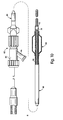
- FIG. 10 illustrates another aspect of the invention in which a low profile single lumen balloon dilatation catheter is adapted to have conventional movable guidewire capability but in which the guidewire also carries a radially expandable element adapted to seal off the distal end of the catheter lumen, beyond the balloon, so that the balloon may be inflated and pressurized to perform a dilatation.
- the catheter includes an elongate flexible tubular shaft 80 formed from an appropriate polymeric material such as high density polyethylene.
- a Y-fitting 82 is attached to the proximal end of the catheter shaft.
- One branch 84 of the Y-fitting 82 is adapted to receive a guidewire in a sealed relation, as by a compressible gasket, such as a Tuo- hy-Borst the of device, while the other branch 86 of the Y-fitting is intended to be connected to an inflation device for inflation and deflation of the balloon.
- a compressible gasket such as a Tuo- hy-Borst the of device
- the distal end of the catheter is provided with a balloon element 88 attached to the shaft as shown.
- the balloon may be formed from a variety of polymeric materials such as polyethylene terephthalate, polyethylene and the like, as is well known in the art.
- the catheter has a single lumen 90 which extends fully through the shaft 80 and the balloon 88 and opens at a distal orifice 92 at the distal tip of the catheter.
- the catheter is used in conjunction with a guidewire of the type described above and illustrated in FIGS. 3, 4 and 5.
- the guidewire in use, the guidewire, with its expandable element 70 in a contracted configuration, may be manipulated through the patient's arteries to place the distal tip of the guidewire through the stenosis to be treated.
- the single lumen catheter then may be advanced over the guidewire to place the balloon portion, in a deflated condition, through the stenosis.
- the radially expandable element 70 of the guidewire may be expanded into engagement with the distal end of the catheter to enhance the pushability of the catheter and improve its column strength as described previously.
- the catheter is filled with inflation liquid, typically a radiopaque liquid, and when the catheter shaft and balloon are filled, the radially expandable element 70 is expanded into sealed relation with the catheter lumen distally of the balloon. With the distal outlet 92 so sealed, the pressure of the inflation liquid then may be increased sufficiently to effect the dilatation of the stenosis.
- inflation liquid typically a radiopaque liquid
- the catheter shaft may be of the order of 135 cm long and may have an internal diameter of the order of 0.018 to 0.020 inches and an outer diameter of about 0.026 to 0.028 inches.
- the catheter thus defines a very low profile and is adapted to be advanced into and through narrow tortuous arteries such as the coronary arteries.
- the inner lumen of the catheter, particularly at the distal end, is dimensioned such that when the expandable element 70 on the guidewire is expanded, it will engage the inner lumen in a snug sealed manner.
- the invention provides improved catheter and guidewire systems adapted to enhance the pushability of the catheter-guidewire combination, and particularly with small diameter catheters that otherwise would tend to have relatively little column strength. Additionally, the systems enable a very small diameter single lumen catheter to be used in which a guidewire may serve in its catheter guiding function as well as in a manner to cooperate with the catheter during inflation and deflation of the balloon.
Landscapes
- Health & Medical Sciences (AREA)
- Life Sciences & Earth Sciences (AREA)
- Biophysics (AREA)
- Pulmonology (AREA)
- Engineering & Computer Science (AREA)
- Anesthesiology (AREA)
- Biomedical Technology (AREA)
- Heart & Thoracic Surgery (AREA)
- Hematology (AREA)
- Animal Behavior & Ethology (AREA)
- General Health & Medical Sciences (AREA)
- Public Health (AREA)
- Veterinary Medicine (AREA)
- Media Introduction/Drainage Providing Device (AREA)
Applications Claiming Priority (2)
| Application Number | Priority Date | Filing Date | Title |
|---|---|---|---|
| US07/603,948 US5265622A (en) | 1990-10-25 | 1990-10-25 | Guidewire having radially expandable member and method for guiding and advancing a catheter using the same |
| US603948 | 1996-02-16 |
Publications (2)
| Publication Number | Publication Date |
|---|---|
| EP0486157A2 true EP0486157A2 (fr) | 1992-05-20 |
| EP0486157A3 EP0486157A3 (en) | 1992-08-05 |
Family
ID=24417557
Family Applications (1)
| Application Number | Title | Priority Date | Filing Date |
|---|---|---|---|
| EP19910309440 Withdrawn EP0486157A3 (en) | 1990-10-25 | 1991-10-15 | Improvements in guidewires and catheters usable therewith |
Country Status (4)
| Country | Link |
|---|---|
| US (1) | US5265622A (fr) |
| EP (1) | EP0486157A3 (fr) |
| JP (1) | JPH0663149A (fr) |
| AU (1) | AU8569191A (fr) |
Cited By (12)
| Publication number | Priority date | Publication date | Assignee | Title |
|---|---|---|---|---|
| US5322513A (en) * | 1992-01-22 | 1994-06-21 | Baxter International Inc. | Easy-to-handle, self-guiding catheter stripper |
| US5378238A (en) * | 1991-10-15 | 1995-01-03 | Scimed Life Systems, Inc. | Innerless dilatation catheter with balloon stretch or manual valve |
| US5554114A (en) * | 1994-10-20 | 1996-09-10 | Micro Therapeutics, Inc. | Infusion device with preformed shape |
| WO1997018006A1 (fr) * | 1995-11-10 | 1997-05-22 | Endogad Research Pty. Limited | Mise en place, dirigee par le flux sanguin, d'un guide metallique endo-luminal |
| US5762615A (en) * | 1996-06-04 | 1998-06-09 | Cordis Corporation | Guideware having a distal tip with variable flexibility |
| WO1998047446A1 (fr) * | 1997-04-24 | 1998-10-29 | Bard Galway Limited | Dispositif et procede pour realiser un ancrage lors de l'implantation d'un stent bifurque |
| WO2003072179A1 (fr) * | 2002-02-26 | 2003-09-04 | Boston Sceintific Limited | Fil-guide destine a une protection embolique et comprenant une butee activable et procedes d'utilisation |
| US6663596B2 (en) | 2001-08-13 | 2003-12-16 | Scimed Life Systems, Inc. | Delivering material to a patient |
| WO2005117754A1 (fr) * | 2004-06-02 | 2005-12-15 | Israel Henry M | Fil de guidage extensible et contractile |
| AU2005202496B2 (en) * | 1999-06-14 | 2008-09-04 | W. L. Gore & Associates, Inc. | Apparatus for removing emboli during an angioplasty or stenting procedure |
| AU2008229661B2 (en) * | 1999-06-14 | 2011-08-11 | W. L. Gore & Associates, Inc. | Apparatus for removing emboli during an angioplasty or stenting procedure |
| EP2152339A4 (fr) * | 2007-08-29 | 2014-04-02 | Circulite Inc | Dispositifs, systèmes et procédés d'introduction de canules comprenant un élément compressible |
Families Citing this family (77)
| Publication number | Priority date | Publication date | Assignee | Title |
|---|---|---|---|---|
| US5484409A (en) * | 1989-08-25 | 1996-01-16 | Scimed Life Systems, Inc. | Intravascular catheter and method for use thereof |
| US5976107A (en) * | 1991-07-05 | 1999-11-02 | Scimed Life Systems. Inc. | Catheter having extendable guide wire lumen |
| US5259839A (en) * | 1991-08-23 | 1993-11-09 | Scimed Life Systems, Inc. | Balloon catheter with guidewire valve |
| US5500180A (en) * | 1992-09-30 | 1996-03-19 | C. R. Bard, Inc. | Method of making a distensible dilatation balloon using a block copolymer |
| US5505699A (en) * | 1994-03-24 | 1996-04-09 | Schneider (Usa) Inc. | Angioplasty device |
| EP1221307B1 (fr) | 1994-07-08 | 2010-02-17 | ev3 Inc. | Système pour effectuer un procédé intravasculaire |
| US5667493A (en) * | 1994-12-30 | 1997-09-16 | Janacek; Jaroslav | Dilation catheter |
| US6702789B1 (en) | 1997-03-11 | 2004-03-09 | Alcove Medical, Inc. | Catheter having insertion control mechanism and anti-bunching mechanism |
| US5830156A (en) * | 1997-04-11 | 1998-11-03 | Cabot Technology Corporation | Slip resistant guidewire |
| US6171297B1 (en) * | 1998-06-30 | 2001-01-09 | Schneider (Usa) Inc | Radiopaque catheter tip |
| US6514260B1 (en) * | 2000-03-15 | 2003-02-04 | Sdgi Holdings, Inc. | Methods and instruments for laparoscopic spinal surgery |
| US6663598B1 (en) * | 2000-05-17 | 2003-12-16 | Scimed Life Systems, Inc. | Fluid seal for endoscope |
| WO2002015958A2 (fr) | 2000-08-24 | 2002-02-28 | Corazon Technologies, Inc. | Systemes de distribution de fluides permettant de distribuer des fluides dans des catheters a lumieres multiples |
| US6527732B1 (en) | 2000-10-17 | 2003-03-04 | Micro Therapeutics, Inc. | Torsionally compensated guidewire |
| US7245959B1 (en) * | 2001-03-02 | 2007-07-17 | Scimed Life Systems, Inc. | Imaging catheter for use inside a guiding catheter |
| US6866677B2 (en) * | 2001-04-03 | 2005-03-15 | Medtronic Ave, Inc. | Temporary intraluminal filter guidewire and methods of use |
| US6818006B2 (en) * | 2001-04-03 | 2004-11-16 | Medtronic Vascular, Inc. | Temporary intraluminal filter guidewire |
| US7044958B2 (en) | 2001-04-03 | 2006-05-16 | Medtronic Vascular, Inc. | Temporary device for capturing embolic material |
| US9480839B2 (en) * | 2002-09-24 | 2016-11-01 | Medtronic, Inc. | Lead delivery device and method |
| US8229572B2 (en) * | 2008-06-27 | 2012-07-24 | Medtronic, Inc. | Lead delivery device and method |
| US9636499B2 (en) * | 2002-09-24 | 2017-05-02 | Medtronic, Inc. | Lead delivery device and method |
| US9849279B2 (en) | 2008-06-27 | 2017-12-26 | Medtronic, Inc. | Lead delivery device and method |
| US8920432B2 (en) * | 2002-09-24 | 2014-12-30 | Medtronic, Inc. | Lead delivery device and method |
| US7250041B2 (en) | 2003-03-12 | 2007-07-31 | Abbott Cardiovascular Systems Inc. | Retrograde pressure regulated infusion |
| US20050015048A1 (en) | 2003-03-12 | 2005-01-20 | Chiu Jessica G. | Infusion treatment agents, catheters, filter devices, and occlusion devices, and use thereof |
| US20040218724A1 (en) * | 2003-04-30 | 2004-11-04 | Chornenky Victor I. | Miniature x-ray emitter |
| EP2286864A3 (fr) | 2004-01-09 | 2011-03-30 | Corazon Technologies, Inc. | Cathéters à lumières multiples et procédés pour leur utilisation |
| US20060047265A1 (en) * | 2004-08-25 | 2006-03-02 | Medtronic Vascular, Inc. | Multi-exchange catheter guide member with improved seal |
| US7976518B2 (en) | 2005-01-13 | 2011-07-12 | Corpak Medsystems, Inc. | Tubing assembly and signal generator placement control device and method for use with catheter guidance systems |
| US7967747B2 (en) * | 2005-05-10 | 2011-06-28 | Boston Scientific Scimed, Inc. | Filtering apparatus and methods of use |
| US8795348B2 (en) * | 2005-06-14 | 2014-08-05 | Boston Scientific Scimed, Inc. | Medical devices and related methods |
| US20070118079A1 (en) * | 2005-11-21 | 2007-05-24 | Moberg John R | Medical devices and related systems and methods |
| US8142468B2 (en) * | 2005-12-22 | 2012-03-27 | Cordis Corporation | Guidewire with distal expansion feature and method for enhancing the deliverability and crossability of medical devices |
| US7682365B2 (en) * | 2006-11-13 | 2010-03-23 | Medtronic Vascular, Inc. | Catheter device for support of a guidewire in crossing a lesion |
| US7941213B2 (en) | 2006-12-28 | 2011-05-10 | Medtronic, Inc. | System and method to evaluate electrode position and spacing |
| US20080195141A1 (en) * | 2007-02-08 | 2008-08-14 | James Teague | Backstop protection device and method of using the same |
| EP2136706A1 (fr) | 2007-04-18 | 2009-12-30 | Medtronic, Inc. | Branchements électriques médicaux à fixation active chroniquement implantables, et procédés afférents pour implantation non fluoroscopique |
| US9034007B2 (en) | 2007-09-21 | 2015-05-19 | Insera Therapeutics, Inc. | Distal embolic protection devices with a variable thickness microguidewire and methods for their use |
| US8231926B2 (en) | 2007-12-21 | 2012-07-31 | Innovatech, Llc | Marked precoated medical device and method of manufacturing same |
| US7811623B2 (en) | 2007-12-21 | 2010-10-12 | Innovatech, Llc | Marked precoated medical device and method of manufacturing same |
| US7714217B2 (en) | 2007-12-21 | 2010-05-11 | Innovatech, Llc | Marked precoated strings and method of manufacturing same |
| US8048471B2 (en) | 2007-12-21 | 2011-11-01 | Innovatech, Llc | Marked precoated medical device and method of manufacturing same |
| US8231927B2 (en) | 2007-12-21 | 2012-07-31 | Innovatech, Llc | Marked precoated medical device and method of manufacturing same |
| US8016851B2 (en) * | 2007-12-27 | 2011-09-13 | Cook Medical Technologies Llc | Delivery system and method of delivery for treating obesity |
| US8457371B2 (en) | 2008-04-18 | 2013-06-04 | Regents Of The University Of Minnesota | Method and apparatus for mapping a structure |
| US8839798B2 (en) | 2008-04-18 | 2014-09-23 | Medtronic, Inc. | System and method for determining sheath location |
| US8494608B2 (en) | 2008-04-18 | 2013-07-23 | Medtronic, Inc. | Method and apparatus for mapping a structure |
| US8663120B2 (en) | 2008-04-18 | 2014-03-04 | Regents Of The University Of Minnesota | Method and apparatus for mapping a structure |
| US8532734B2 (en) | 2008-04-18 | 2013-09-10 | Regents Of The University Of Minnesota | Method and apparatus for mapping a structure |
| US8340751B2 (en) | 2008-04-18 | 2012-12-25 | Medtronic, Inc. | Method and apparatus for determining tracking a virtual point defined relative to a tracked member |
| US9775989B2 (en) * | 2008-06-27 | 2017-10-03 | Medtronic, Inc. | Lead delivery device and method |
| US11931523B2 (en) | 2008-06-27 | 2024-03-19 | Medtronic, Inc. | Lead delivery device and method |
| US9775990B2 (en) * | 2008-06-27 | 2017-10-03 | Medtronic, Inc. | Lead delivery device and method |
| JP5313613B2 (ja) * | 2008-10-06 | 2013-10-09 | 株式会社グツドマン | カテーテル |
| US8021330B2 (en) * | 2008-11-14 | 2011-09-20 | Medtronic Vascular, Inc. | Balloon catheter for crossing a chronic total occlusion |
| US8175681B2 (en) | 2008-12-16 | 2012-05-08 | Medtronic Navigation Inc. | Combination of electromagnetic and electropotential localization |
| US20110022026A1 (en) | 2009-07-21 | 2011-01-27 | Lake Region Manufacturing, Inc. d/b/a Lake Region Medical. Inc. | Methods and Devices for Delivering Drugs Using Drug-Delivery or Drug-Coated Guidewires |
| US8494614B2 (en) | 2009-08-31 | 2013-07-23 | Regents Of The University Of Minnesota | Combination localization system |
| US8494613B2 (en) | 2009-08-31 | 2013-07-23 | Medtronic, Inc. | Combination localization system |
| US8355774B2 (en) | 2009-10-30 | 2013-01-15 | Medtronic, Inc. | System and method to evaluate electrode position and spacing |
| WO2012090156A1 (fr) * | 2010-12-27 | 2012-07-05 | S-Ballon | Méthode et dispositif de traitement de la sténose |
| US8900652B1 (en) | 2011-03-14 | 2014-12-02 | Innovatech, Llc | Marked fluoropolymer surfaces and method of manufacturing same |
| US9028441B2 (en) | 2011-09-08 | 2015-05-12 | Corpak Medsystems, Inc. | Apparatus and method used with guidance system for feeding and suctioning |
| US20140180166A1 (en) * | 2012-12-20 | 2014-06-26 | Cook Medical Technologies Llc | Guide wire |
| WO2014102599A1 (fr) | 2012-12-31 | 2014-07-03 | Clearstream Technologies Limited | Fil-guide radio-opaque destiné à faciliter l'alignement d'un cathéter |
| CN104968389B (zh) | 2012-12-31 | 2018-11-06 | 明讯科技有限公司 | 辐射不可透过的球囊导管以及用于方便对齐的导丝 |
| US8679150B1 (en) | 2013-03-15 | 2014-03-25 | Insera Therapeutics, Inc. | Shape-set textile structure based mechanical thrombectomy methods |
| CA2901443A1 (fr) | 2013-03-15 | 2014-09-25 | Insera Therapeutics, Inc. | Dispositifs et procedes de traitement vasculaire |
| US8715314B1 (en) | 2013-03-15 | 2014-05-06 | Insera Therapeutics, Inc. | Vascular treatment measurement methods |
| US8690907B1 (en) | 2013-03-15 | 2014-04-08 | Insera Therapeutics, Inc. | Vascular treatment methods |
| EP3444002B1 (fr) | 2013-04-22 | 2025-06-04 | University of Maryland, Baltimore | Dispositifs à ultrasons de coaptation |
| US9993624B2 (en) | 2014-08-08 | 2018-06-12 | DePuy Synthes Products, Inc. | Step feature for steerable guidewires |
| EP3416568A4 (fr) | 2016-02-16 | 2019-10-16 | Insera Therapeutics, Inc. | Dispositifs d'aspiration et dispositifs de déviation de flux ancrés |
| WO2017176881A1 (fr) | 2016-04-05 | 2017-10-12 | University Of Maryland, Baltimore | Procédé et appareil pour une gastrostomie à ultrasons de coaptation |
| US10806911B2 (en) * | 2018-01-12 | 2020-10-20 | Biosense Webster (Israel) Ltd. | Balloon catheter assisted by pulling a puller-wire |
| AU2019257771A1 (en) | 2018-04-27 | 2020-11-26 | CoapTech, Inc. | Systems, apparatus, and methods for placing a guidewire for a gastrostomy tube |
| WO2022170187A1 (fr) | 2021-02-05 | 2022-08-11 | Pyne Devaraj | Dispositif et méthodes d'embolisation à ballonnet détachable |
Family Cites Families (14)
| Publication number | Priority date | Publication date | Assignee | Title |
|---|---|---|---|---|
| US3706883A (en) * | 1969-11-21 | 1972-12-19 | Kevin M Mcintyre | Radiological apparatus for measuring length which comprises two relatively movable radio opaque marks |
| US3996938A (en) * | 1975-07-10 | 1976-12-14 | Clark Iii William T | Expanding mesh catheter |
| DE2821048C2 (de) * | 1978-05-13 | 1980-07-17 | Willy Ruesch Gmbh & Co Kg, 7053 Kernen | Medizinisches Instrument |
| SE445884B (sv) * | 1982-04-30 | 1986-07-28 | Medinvent Sa | Anordning for implantation av en rorformig protes |
| US4545390A (en) * | 1982-09-22 | 1985-10-08 | C. R. Bard, Inc. | Steerable guide wire for balloon dilatation procedure |
| ES2000247A4 (es) * | 1986-05-23 | 1988-02-01 | Sarcem Sa | Cateter-guia |
| US4846174A (en) * | 1986-08-08 | 1989-07-11 | Scimed Life Systems, Inc. | Angioplasty dilating guide wire |
| US4808163A (en) * | 1987-07-29 | 1989-02-28 | Laub Glenn W | Percutaneous venous cannula for cardiopulmonary bypass |
| US4813934A (en) * | 1987-08-07 | 1989-03-21 | Target Therapeutics | Valved catheter device and method |
| US4848344A (en) * | 1987-11-13 | 1989-07-18 | Cook, Inc. | Balloon guide |
| JPH01145074A (ja) * | 1987-12-01 | 1989-06-07 | Terumo Corp | バルーンカテーテル |
| US4932959A (en) * | 1988-12-01 | 1990-06-12 | Advanced Cardiovascular Systems, Inc. | Vascular catheter with releasably secured guidewire |
| US4922924A (en) * | 1989-04-27 | 1990-05-08 | C. R. Bard, Inc. | Catheter guidewire with varying radiopacity |
| US5002560A (en) * | 1989-09-08 | 1991-03-26 | Advanced Cardiovascular Systems, Inc. | Expandable cage catheter with a rotatable guide |
-
1990
- 1990-10-25 US US07/603,948 patent/US5265622A/en not_active Expired - Fee Related
-
1991
- 1991-10-09 AU AU85691/91A patent/AU8569191A/en not_active Abandoned
- 1991-10-15 EP EP19910309440 patent/EP0486157A3/en not_active Withdrawn
- 1991-10-25 JP JP3279964A patent/JPH0663149A/ja active Pending
Cited By (15)
| Publication number | Priority date | Publication date | Assignee | Title |
|---|---|---|---|---|
| US5378238A (en) * | 1991-10-15 | 1995-01-03 | Scimed Life Systems, Inc. | Innerless dilatation catheter with balloon stretch or manual valve |
| US5322513A (en) * | 1992-01-22 | 1994-06-21 | Baxter International Inc. | Easy-to-handle, self-guiding catheter stripper |
| US5554114A (en) * | 1994-10-20 | 1996-09-10 | Micro Therapeutics, Inc. | Infusion device with preformed shape |
| WO1997018006A1 (fr) * | 1995-11-10 | 1997-05-22 | Endogad Research Pty. Limited | Mise en place, dirigee par le flux sanguin, d'un guide metallique endo-luminal |
| US5762615A (en) * | 1996-06-04 | 1998-06-09 | Cordis Corporation | Guideware having a distal tip with variable flexibility |
| WO1998047446A1 (fr) * | 1997-04-24 | 1998-10-29 | Bard Galway Limited | Dispositif et procede pour realiser un ancrage lors de l'implantation d'un stent bifurque |
| AU2008229661B2 (en) * | 1999-06-14 | 2011-08-11 | W. L. Gore & Associates, Inc. | Apparatus for removing emboli during an angioplasty or stenting procedure |
| AU2005202496B2 (en) * | 1999-06-14 | 2008-09-04 | W. L. Gore & Associates, Inc. | Apparatus for removing emboli during an angioplasty or stenting procedure |
| US7270654B2 (en) | 2001-08-13 | 2007-09-18 | Boston Scientific Scimed, Inc. | Delivering material to a patient |
| US6663596B2 (en) | 2001-08-13 | 2003-12-16 | Scimed Life Systems, Inc. | Delivering material to a patient |
| WO2003072179A1 (fr) * | 2002-02-26 | 2003-09-04 | Boston Sceintific Limited | Fil-guide destine a une protection embolique et comprenant une butee activable et procedes d'utilisation |
| US7118539B2 (en) | 2002-02-26 | 2006-10-10 | Scimed Life Systems, Inc. | Articulating guide wire for embolic protection and methods of use |
| WO2005117754A1 (fr) * | 2004-06-02 | 2005-12-15 | Israel Henry M | Fil de guidage extensible et contractile |
| EP2152339A4 (fr) * | 2007-08-29 | 2014-04-02 | Circulite Inc | Dispositifs, systèmes et procédés d'introduction de canules comprenant un élément compressible |
| EP2891502A1 (fr) * | 2007-08-29 | 2015-07-08 | CircuLite, Inc. | Dispositifs, systèmes et procédés d'introduction de canules comprenant un élément compressible |
Also Published As
| Publication number | Publication date |
|---|---|
| JPH0663149A (ja) | 1994-03-08 |
| EP0486157A3 (en) | 1992-08-05 |
| AU8569191A (en) | 1992-04-30 |
| US5265622A (en) | 1993-11-30 |
Similar Documents
| Publication | Publication Date | Title |
|---|---|---|
| US5265622A (en) | Guidewire having radially expandable member and method for guiding and advancing a catheter using the same | |
| US5102390A (en) | Microdilatation probe and system for performing angioplasty in highly stenosed blood vessels | |
| USRE34633E (en) | Balloon guide | |
| US5779731A (en) | Balloon catheter having dual markers and method | |
| US6245040B1 (en) | Perfusion balloon brace and method of use | |
| JP2505932B2 (ja) | 脈管形成膨張風船型カテ―テル/ガイドワイヤシステム | |
| US4572186A (en) | Vessel dilation | |
| US5304198A (en) | Single-lumen balloon catheter having a directional valve | |
| CA1278233C (fr) | Fil-guide orientable de faible diametre a extremite reglable | |
| EP0416734B1 (fr) | Cathéter guide et fils de guidage pour effecteur un échange rapide de cathéter | |
| US4530698A (en) | Method and apparatus for traversing blood vessels | |
| US5328469A (en) | Hybrid balloon angioplasty catheter and methods of use | |
| US5370617A (en) | Blood perfusion balloon catheter | |
| EP2446919B1 (fr) | Ballonnet PTA coaxial | |
| US5882334A (en) | Balloon/delivery catheter assembly with adjustable balloon positioning | |
| US5090958A (en) | Balloon catheters | |
| US5409470A (en) | Dilatation catheter and guidewire with threaded tip connection | |
| EP0440345A1 (fr) | Cathéter à ballonnet et système de fil de guidage | |
| US5683410A (en) | Single-lumen balloon catheter having a directional valve | |
| WO1998058697A1 (fr) | Fil-guide a rigidite variable pour angioplastie | |
| AU654821B2 (en) | PTCA catheter having an optionally fixated corewire | |
| US5700242A (en) | Balloon catheter and method for facilitating increased radial expansion | |
| EP0565996A1 (fr) | Méthode de dilatation vasculaire et dispositif pour faciliter d'échange d'un ballon à dilatation |
Legal Events
| Date | Code | Title | Description |
|---|---|---|---|
| PUAI | Public reference made under article 153(3) epc to a published international application that has entered the european phase |
Free format text: ORIGINAL CODE: 0009012 |
|
| AK | Designated contracting states |
Kind code of ref document: A2 Designated state(s): BE DE ES FR GB IT NL |
|
| PUAL | Search report despatched |
Free format text: ORIGINAL CODE: 0009013 |
|
| AK | Designated contracting states |
Kind code of ref document: A3 Designated state(s): BE DE ES FR GB IT NL |
|
| 17P | Request for examination filed |
Effective date: 19920930 |
|
| 17Q | First examination report despatched |
Effective date: 19940506 |
|
| STAA | Information on the status of an ep patent application or granted ep patent |
Free format text: STATUS: THE APPLICATION IS DEEMED TO BE WITHDRAWN |
|
| 18D | Application deemed to be withdrawn |
Effective date: 19950801 |