EP0486253A2 - Verfahren und Gerät zum Feststellen der Tonerrestmenge in einer Bilderzeugungsvorrichtung - Google Patents
Verfahren und Gerät zum Feststellen der Tonerrestmenge in einer Bilderzeugungsvorrichtung Download PDFInfo
- Publication number
- EP0486253A2 EP0486253A2 EP91310411A EP91310411A EP0486253A2 EP 0486253 A2 EP0486253 A2 EP 0486253A2 EP 91310411 A EP91310411 A EP 91310411A EP 91310411 A EP91310411 A EP 91310411A EP 0486253 A2 EP0486253 A2 EP 0486253A2
- Authority
- EP
- European Patent Office
- Prior art keywords
- toner
- average value
- equal
- mixing member
- threshold level
- Prior art date
- Legal status (The legal status is an assumption and is not a legal conclusion. Google has not performed a legal analysis and makes no representation as to the accuracy of the status listed.)
- Granted
Links
Images


Classifications
-
- G—PHYSICS
- G03—PHOTOGRAPHY; CINEMATOGRAPHY; ANALOGOUS TECHNIQUES USING WAVES OTHER THAN OPTICAL WAVES; ELECTROGRAPHY; HOLOGRAPHY
- G03G—ELECTROGRAPHY; ELECTROPHOTOGRAPHY; MAGNETOGRAPHY
- G03G15/00—Apparatus for electrographic processes using a charge pattern
- G03G15/06—Apparatus for electrographic processes using a charge pattern for developing
- G03G15/08—Apparatus for electrographic processes using a charge pattern for developing using a solid developer, e.g. powder developer
- G03G15/0822—Arrangements for preparing, mixing, supplying or dispensing developer
- G03G15/0848—Arrangements for testing or measuring developer properties or quality, e.g. charge, size, flowability
- G03G15/0856—Detection or control means for the developer level
-
- G—PHYSICS
- G03—PHOTOGRAPHY; CINEMATOGRAPHY; ANALOGOUS TECHNIQUES USING WAVES OTHER THAN OPTICAL WAVES; ELECTROGRAPHY; HOLOGRAPHY
- G03G—ELECTROGRAPHY; ELECTROPHOTOGRAPHY; MAGNETOGRAPHY
- G03G15/00—Apparatus for electrographic processes using a charge pattern
- G03G15/06—Apparatus for electrographic processes using a charge pattern for developing
- G03G15/08—Apparatus for electrographic processes using a charge pattern for developing using a solid developer, e.g. powder developer
- G03G15/0822—Arrangements for preparing, mixing, supplying or dispensing developer
- G03G15/0848—Arrangements for testing or measuring developer properties or quality, e.g. charge, size, flowability
- G03G15/0849—Detection or control means for the developer concentration
-
- G—PHYSICS
- G03—PHOTOGRAPHY; CINEMATOGRAPHY; ANALOGOUS TECHNIQUES USING WAVES OTHER THAN OPTICAL WAVES; ELECTROGRAPHY; HOLOGRAPHY
- G03G—ELECTROGRAPHY; ELECTROPHOTOGRAPHY; MAGNETOGRAPHY
- G03G2215/00—Apparatus for electrophotographic processes
- G03G2215/06—Developing structures, details
- G03G2215/0602—Developer
- G03G2215/0604—Developer solid type
- G03G2215/0607—Developer solid type two-component
- G03G2215/0609—Developer solid type two-component magnetic brush
Definitions
- the invention relates to a method and apparatus for detecting the residual quantity of the toner in an image forming device, and particularly to the method and apparatus for detecting the amount of toner in image forming devices such as electrophotographic printers and copy machines in which the toner is mixed by a mixing member during the printing operation thereof.
- an electrostatic latent image corresponding to an image to be printed or copied is optically formed on a photoconductor drum.
- the latent image is then developed with a toner into a toner image, which is transferred to and fixed on a recording sheet to complete the printing or copying.
- the toner is gradually consumed.
- a printed or copied image becomes thin to provide an unclear printed or copied image.
- the toner sensor detects the residual quantity or density of the toner and the output voltage in accordance with the amount of the toner.
- the image forming device is equipped with at least one toner indicator for indicating a replenishment of the toner or replacement of a toner container. And when the quantity or density of the toner becomes below a specified value, the toner indicator is turned on to inform the user to replenish the toner or replacing the toner container.
- Figure 1 is a sectional view showing a conventional developing unit employed for electrophotographic printers, etc.
- numeral 1 denotes the developing unit, and 2 a photoconductor drum.
- numeral 10 denotes a mixing portion for mixing a toner and charging the toner through friction, 20 a toner separating portion, 30 a toner sensor, and 9 the toner.
- a toner mixing member 11 stirs and frictionally charges the toner 9.
- the toner 9 is fed to a magnet roll 21 of the toner separating portion 20.
- the magnet roll 21 is rotated, and the toner 9 is carried on the surface of the magnet roll.
- the height of the toner is regulated by a doctor blade 22.
- the toner comes in contact with the surface of the photoconductor drum 2 facing the magnet roll. According to a difference between a bias voltage applied to the magnet roll 21 and the surface potential of the photoconductor drum 2, the toner is transferred onto an electrostatic latent image formed on the surface of the photoconductor drum, thereby forming a toner image.
- FIG. 2 shows a perspective explanatory view showing the mixing member 11 in Fig. 1.
- the mixing member 11 has a rotational shaft on which four arms 11a are planted. Two of the arms 11a are planted on the same side of the shaft 11 c and the other two arms 11a are planted on the opposite side thereof, and each free end of the arms 11a are connected by two bars 11 b.
- the toner sensor 30 is fitted to a toner container 12 to detect the residual quantity or density of the toner.
- the toner sensor 30 comprises a differential transformer including a drive coil L1, a reference coil L2, and a detection coil L3. These coils L1, L2 and L3 are wound around the same core 31.
- a high-frequency signal of 500 KHz is applied to the drive coil L1 from an oscillator OSC.
- developer for the image forming device
- one is an one-component developer comprised of only the toner and the other is a two-component developer comprised of the toner and a magnetic carrier such as ferrite or iron.
- a new type of the two-component developer wherein the rate of the carrier is very small as compared with the rate of the toner is used.
- This new type of the the two-component developer is sometimes called 1.5 component developer.
- the two-component developer which is a mixture of the magnetic carriers and the nonmagnetic toner
- the density of the toner is high in a given volume, that of the carriers (magnetic substances) is thin to increase the magnetic resistance.
- the toner sensor 30 cannot detect the density of the toner, but as the toner is consumed, the magnetic resistance of the developer changes depending on whether the developer is above, below, or around the surface of the toner sensor. Accordingly, the residual quantity of the toner is detectable according to an output Vo of the toner sensor 30.
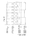
- the toner sensor 30 While the toner sensor 30 is detecting the residual quantity of the toner 9, the toner 9 is stirred and moved by the mixing member 11.
- the output voltage Vo of the toner sensor 30, therefore, oscillates as shown in Fig. 5 during a rotational period of the mixing member 11.
- the mixing member 11 starts to rotate at time t1, the rotational speed thereof becomes constant after time t2, and a printing operation of the image forming device is carried out between time t2 and t3.
- the rotational speed of the mixing member 11 decreases after time t3, and the mixing member 11 stops at time t4.
- the amplitude of the output voltage Vo of the toner sensor 30 is greatly changed according to acceleration or deceleration of the rotation of the mixing member 11.
- the output voltage Vo of the toner sensor 30 indicates a high or low value.
- the mixing member 11 moves the toner 9 onto the toner sensor 30 and stops, the output voltage Vo of the toner sensor 30 will be high. This condition is indicated by a dot and dash line in Fig. 3.
- the output voltage Vo of the toner sensor 30 will be low because the quantity of the toner 9 over the toner sensor 30 has been reduced by the mixing member 11. This condition is indicated by phantom line in Fig. 3
- the output voltage Vo of the toner sensor 30 When detecting the density of the toner 9, the output voltage Vo of the toner sensor 30 also fluctuates depending on the rotation of the mixing member 11. Namely, the output voltage Vo becomes larger or smaller depending on a stopping state of the mixing member 11, and therefore, the density of the toner 9 is not correctly detected.
- An object of the invention is, therefore, to provide a toner quantity detecting method that correctly detects the residual quantity or density of toner.
- the output voltage of the toner sensor 30 is sampled at every predetermined time period after the rotational speed of the mixing member becomes constant, and averages the predetermined number of sampled values to provide data for the residual quantity or density of the toner.
- the predetermined number of sampled values may be equal to the sampling times in a certain time period that is substantially a random number times a rotational period of the mixing member 11.
- the output voltage Vo of the toner sensor 30 provides a regular waveform.
- sampling of the output voltage of the toner sensor 30 is carried out at predetermined times during a predetermined period according to the present invention, and the sampled values are taken an average to provide data for the residual quantity or density of the toner.
- the residual quantity or density of the toner is stably provided with no influence of the rotation on the mixing member 11.
- the toner gathering in clods may be separated into particles and the toner sticking to walls may be removed, so that the residual quantity and density of the toner may be more stably detected.
- the sampled values of the output voltage of the sensor are averaged for a period that is a random number times a rotational period of the mixing member, to provide data for the residual quantity or density of the toner. Namely, the output voltage of the toner sensor, which is oscillating, is sampled at various temporal points and averaged to provide stabilized data for the residual quantity or density of the toner.
- the averaged toner residual quantity is compared with a near-empty value or an empty value, and a toner near end signal or a toner end signal is correctly provided.
- Figure 6 is a schematic view showing one embodiment of the present invention.
- numeral 1 denotes a developing unit
- 2 a photoconductor drum
- 3 a process motor for rotating a mixing member 11
- 4 a process motor driving circuit
- 5 a rotational speed detecting portion for detecting the rotational speed of the process motor 3 and providing a constant speed signal CVE once the motor speed reaches a specific speed
- 6 an AD converter for converting an output of a toner sensor 30, and 7 a signal processing portion for averaging output values of the toner sensor 30 and providing data for the residual quantity (orden- sity) of the toner 9.
- numeral 10 denotes a mixing portion for mixing the toner 9 stored in a toner container 12 with the mixing member 11 rotated by the process motor 3.
- Numeral 20 denotes a tonerseparat- ing portion including a magnet roll 21 for guiding the toner toward the photoconductor drum 2, and a doctor blade 22 for regulating the height of the toner.
- Numeral 30 denotes the toner sensor for detecting the residual quantity or density of the toner 9.
- the toner 9 is, for example, a 1.5 components developer in this embodiment.
- the signal processing portion 7 comprises a microcomputer and includes an input/output (I/O) interface 71, a central processing unit (CPU) 72, a read only memory (ROM) for storing a program, and a random access memory (RAM) for storing various data.
- I/O interface 71, the CPU 72, the ROM 73, and the RAM 74 are interconnected by bus line 75.
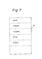
- Fig. 7 is a explanatory view showing a content of the RAM in Fig. 6.
- a variety of data such as ADCR, TNSBUF, TNEMPC, STNR, STEND, and so on, which will be explained later, are stored and renewed by the new data.
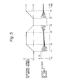
- Figure 8 is a view showing a relationship between a rotational speed of the mixing member 11 and an output voltage Vo of the toner sensor 30 in detecting the residual quantity of the toner 9.
- the output voltage Vo of the toner sensor 30 forms a regular waveform for a rotational period of the mixing member 11 due to a balance between the movement of the toner 9 and a responding speed of the toner sensor 30.
- a period of the waveform of the output voltage Vo of the toner sensor 30 agrees with the rotational period of the mixing member 11, so that the data for the residual quantity of the toner 9 may be more stabilized and be more reliable if a period for averaging the sampled values is set to be substantially a random number times the rotational period of the mixing member 11.
- Vom represents an averaged value (data for the residual quantity of the toner 9) calculated with an averaging period of twice the rotational period of the mixing member 11, and Vom' an averaged value (data for the residual quantity of the toner 9) calculated with an averaging period of 2.5 times the rotational period of the mixing member 11.
- the data for the residual quantity of the toner 9 is constant.
- the data for the residual quantity of the toner 9 pulsates.
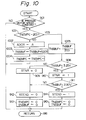
- FIG. 9 is a flowchart showing one embodiment of the method of detecting the residual quantity of the toner according to the present invention executed at every toner sampling period.
- a detecting period of the toner amount is 1.2 sec, which is a random number times of a mixing period i.e., one rotational time of the mixing member 11, and the number of sampling is200 times per 1.2 sec.
- a new sampled value ADCR in the processing portion 7, which is equal to the output value A of the A/D converter 6, and a previous average TNSBUF are averaged as follows: TNSBUF +- (ADCR + TNSBUF)/2.
- the CPU 72 of the signal processing portion 7 monitors whether or not the rotational speed of the process motor 3 is constant, so that at step 901, it is determined whether or not the process motor speed is constant.
- the rotational speed detecting portion 5 provides the constant speed signal CVE and when it becomes a sampling time, the CPU 72 checks to see whether or not an empty counter TNEMPC (ini- i-tially 0) stored in the RAM 74 is 0, thereby it is determined whether or not the empty counter TNEMPC is equal to 0 at step 902.
- the result of the determination at step 902 will be "YES" because the empty counterTNEMPC is set to 0 after the initialization, so that the control proceeds to step 903.
- An output A of the AD converter 6 is set in the RAM 74 as ADCR at step 903 and as TNSBUF at step 904.
- step 905 the output A of the AD converter 6 is read at a sampling time and set as ADCR, and the TNSBUF indicating the residual quantity of the toner is updated as follows:
- step 906 the empty counter TNEMPC is incremented by +1 (TNEMPC + 1) and at step 907, it is determined whether or not the count value of the empty counter TNEMPC is more than or equal to 200, i.e., whether or not the sampled value averaging period of 1.2 sec has passed. If the empty counter TNEMPC is less than 200, the control proceeds to step 916 and this routine is completed. Then the steps starting from step 901 are repeated after the sampling time and steps 901 to 907 are repeated until the counter TNEMPC counts 200.
- step 908 it is determined whether or not the TNSBUF, which is indicating the residual quantity of the toner, is smaller than a near empty threshold value of 3.25 V at step 908. If TNSBUF a 3.25 V, the control proceeds to step 909, 912, and 913 accordingly in which a near empty flag STNR (initially 0), a toner end flag STEND (initially 0), and the empty counter TNEMPC are cleared to 0. Then the control proceeds to step 916 to complete this routine, and the steps starting from step 901 are repeated.
- TNSBUF which is indicating the residual quantity of the toner
- the TNSBUF indicating the residual quantity of the toner may become smaller than the near empty threshold value of 3.25 V. Then, if TNSBUF ⁇ 3.25 V at step 908, the control proceeds to step 901 in which the near flag STNR is set to 1, and a toner near the end detected signal is provided to display this situation on a display portion of the apparatus which will be explained later.
- step 911 it is determined whether or not the TNSBUF is smaller than an empty threshold value of 2.90 V, and if TNSBU F a 2.90 V, the control proceeds to step 912 and 913 and a toner end flag STEND (initially 0), and the empty counter TNEMPC are cleared to 0.
- step 911 If the toner is not replenished and further consumed and if the value TNSBUF indicating the residual quantity of the toner becomes smaller than the empty threshold value of 2.90 V, the indication of step 911 will be "YES.” If TNSBUF ⁇ 2.90 V, the control proceeds to step 914 and the toner end flag STEND is then set to 1, and a toner end detected signal is provided to display this situation on the display portion of the apparatus, which will be explained later. Then at step 915, the empty counter TNEMPC is cleared to 0, and this routine is completed at step 916.
- the toner gathering in clods will be separated into particles, and the toner sticking to the walls removed, to provide more stabilized data for the residual quantity of the toner.
- Figure 10 is a flowchart showing another embodiment of the method of detecting the residual quantity of the toner according to the present invention.
- the residual quantity of the toner indicating value TNSBUF is calculated at every sampling time period, although it is calculated at every sampled value averaging period of 1, 2 sec.
- step 1002 it is determined whether or not the empty counter TNEMPC is equal to the number of sampling times of 200 in 1.2 sec at step 1001 after the execution of step 901. If TENMPC ⁇ 200, the control proceeds to step 1002, 1003, and 1004. At step 1002, the output A of the AD converter 6 is read and set as ADCR, and at step 1003, the TNSBUF indicating the residual quantity of the toner is accumulated by ADCR as follows: TNSBUF - TNSBUF + ADCR
- step 1004 the empty counter TNEMPC is incremented by +1 (TNEMPC + 1) and this routine is completed at step 916.
- step 1005 the residual quantity of the toner indicating value TNSBUF which is 200 accumulations of ADCR, is divided by 200 to calculate the average value of the output A of the AD converter 6. Explanation of steps 908 to 916 are omitted since it has already been explained with Fig. 9.
- Figure 11 is a flowchart showing one embodiment of an alarm operation when the amount of the toner is less than the predetermined value according to the present invention.
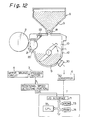
- FIG. 12 is a schematic view showing another embodiment of the apparatus detecting the density of the toner according to the present invention.
- a toner replenishing container 8 having a toner feed roller 81 at the bottom thereof and filled with a lot of toner 9 is added on the toner container 12.
- Figure 13 is a flowchart showing one embodiment of a toner supply operation of the image forming device shown in Fig. 12.
- the embodiment mentioned above observes whether or not the residual quantity of the toner has become smaller than the near empty threshold or the empty threshold, and if it is smaller than one of them, provides the toner near end signal or the toner end signal. Instead, the value TNSBUF indicating the residual quantity of the toner may be provided.
- the invention averages sampled values to provide data for the residual quantity or density of toner.
- This data for the residual quantity or density of the toner provided by the invention is stabilized because the data is not influenced by a rotation of the mixing member.
- the invention starts to sample the residual quantity or density of the toner, so that the toner gathering in clods may be separated into particles and the toner sticking to walls removed, thereby providing more stabilized data for the residual quantity or density of the toner.
- the invention averages sampled values of the output voltage of the sensor for a period that is a random number times a rotational period of the mixing member, to provide data for the residual quantity or density of the toner.
- the output voltage of the toner sensor that fluctuates is sampled at various temporal points and averaged to provide stabilized data for the residual quantity or density of the toner.
- the averaged residual quantity of the toner is compared with a near empty value or an empty value to correctly provide a toner near end signal or a toner end signal.
Landscapes
- Physics & Mathematics (AREA)
- General Physics & Mathematics (AREA)
- Dry Development In Electrophotography (AREA)
Applications Claiming Priority (2)
| Application Number | Priority Date | Filing Date | Title |
|---|---|---|---|
| JP306841/90 | 1990-11-13 | ||
| JP2306841A JPH04177381A (ja) | 1990-11-13 | 1990-11-13 | トナー量検出方法 |
Publications (3)
| Publication Number | Publication Date |
|---|---|
| EP0486253A2 true EP0486253A2 (de) | 1992-05-20 |
| EP0486253A3 EP0486253A3 (de) | 1994-03-23 |
| EP0486253B1 EP0486253B1 (de) | 1996-06-12 |
Family
ID=17961901
Family Applications (1)
| Application Number | Title | Priority Date | Filing Date |
|---|---|---|---|
| EP91310411A Expired - Lifetime EP0486253B1 (de) | 1990-11-13 | 1991-11-12 | Verfahren und Gerät zum Feststellen der Tonerrestmenge in einer Bilderzeugungsvorrichtung |
Country Status (4)
| Country | Link |
|---|---|
| US (1) | US5214475A (de) |
| EP (1) | EP0486253B1 (de) |
| JP (1) | JPH04177381A (de) |
| DE (1) | DE69120210T2 (de) |
Cited By (2)
| Publication number | Priority date | Publication date | Assignee | Title |
|---|---|---|---|---|
| EP0506423A3 (en) * | 1991-03-29 | 1994-09-14 | Fujitsu Ltd | Toner quantity detecting system for an image recording apparatus, a method of detecting the quantity of toner and a developing device for the image recording apparatus |
| EP0777158A1 (de) * | 1995-11-29 | 1997-06-04 | Mita Industrial Co. Ltd. | Entwicklungsgerät |
Families Citing this family (14)
| Publication number | Priority date | Publication date | Assignee | Title |
|---|---|---|---|---|
| US5532790A (en) * | 1992-11-13 | 1996-07-02 | Minolta Camera Kabushiki Kaisha | Device for optically detecting an amount of remaining developer in an image forming apparatus |
| US5436704A (en) * | 1993-05-31 | 1995-07-25 | Samsung Electronics Co., Ltd. | Device for sensing the amount of residual toner of developing apparatus |
| JP3518616B2 (ja) * | 1993-10-22 | 2004-04-12 | 富士ゼロックス株式会社 | トナーエンプティ検出方法及びその装置 |
| KR0132011B1 (ko) * | 1994-02-28 | 1998-10-01 | 김광호 | 현상제 보유 레벨 검출 장치 |
| US5532802A (en) * | 1995-01-13 | 1996-07-02 | Eastman Kodak Company | Piezoelectric sensor for in-situ monitoring of electrostatographic developers |
| JP3351749B2 (ja) * | 1998-10-20 | 2002-12-03 | ペンタックス株式会社 | トナー残量センサ用清掃具 |
| JP2000131936A (ja) * | 1998-10-27 | 2000-05-12 | Canon Inc | 画像形成装置及び現像剤残量検知装置 |
| JP3715897B2 (ja) * | 2000-02-15 | 2005-11-16 | キヤノン株式会社 | プロセスカートリッジ及び電子写真画像形成装置 |
| US20030206982A1 (en) * | 2002-04-24 | 2003-11-06 | Antje Spors | Method of improving dietary balance using gustatory and olfactory aliesthesia |
| US7280776B2 (en) * | 2003-08-25 | 2007-10-09 | Lexmark International, Inc. | Method and apparatus to control waste toner collection in an image forming apparatus |
| JP2006268034A (ja) * | 2005-02-28 | 2006-10-05 | Sharp Corp | 現像装置、それを備えた画像形成装置、現像装置の制御方法、現像装置制御プログラム、およびコンピュータ読み取り可能な記録媒体 |
| CN100428073C (zh) * | 2005-02-28 | 2008-10-22 | 夏普株式会社 | 显影装置及其控制方法、具有该显影装置的图像形成装置 |
| JP4650035B2 (ja) * | 2005-03-11 | 2011-03-16 | 富士ゼロックス株式会社 | トナー補給装置及び画像形成装置 |
| JP2008281844A (ja) * | 2007-05-11 | 2008-11-20 | Ricoh Co Ltd | 現像方法、現像装置、画像形成方法、画像形成装置、消費量演算装置、プロセスカートリッジ |
Family Cites Families (9)
| Publication number | Priority date | Publication date | Assignee | Title |
|---|---|---|---|---|
| JPS5810761A (ja) * | 1981-07-14 | 1983-01-21 | Ricoh Co Ltd | トナ−濃度検知方法 |
| US4647185A (en) * | 1981-10-23 | 1987-03-03 | Canon Kabushiki Kaisha | Developer detecting device |
| JPS6169556A (ja) * | 1984-09-10 | 1986-04-10 | 株式会社 ナシヨナルマリンプラスチツク | 保形用支持部材を備えた輸送袋 |
| JPS62182733A (ja) * | 1986-02-06 | 1987-08-11 | Toshiba Corp | 画像形成装置 |
| JPS6339249U (de) * | 1986-08-29 | 1988-03-14 | ||
| JPS63106679A (ja) * | 1986-10-23 | 1988-05-11 | Minolta Camera Co Ltd | 現像装置 |
| JPS647085A (en) * | 1987-06-30 | 1989-01-11 | Mita Industrial Co Ltd | Toner concentration controller |
| JPS6425175A (en) * | 1987-07-22 | 1989-01-27 | Toshiba Corp | Toner concentration controller |
| JP2965041B2 (ja) * | 1988-11-08 | 1999-10-18 | 株式会社リコー | 画像形成装置 |
-
1990
- 1990-11-13 JP JP2306841A patent/JPH04177381A/ja active Pending
-
1991
- 1991-11-12 EP EP91310411A patent/EP0486253B1/de not_active Expired - Lifetime
- 1991-11-12 DE DE69120210T patent/DE69120210T2/de not_active Expired - Fee Related
- 1991-11-13 US US07/791,126 patent/US5214475A/en not_active Expired - Lifetime
Cited By (2)
| Publication number | Priority date | Publication date | Assignee | Title |
|---|---|---|---|---|
| EP0506423A3 (en) * | 1991-03-29 | 1994-09-14 | Fujitsu Ltd | Toner quantity detecting system for an image recording apparatus, a method of detecting the quantity of toner and a developing device for the image recording apparatus |
| EP0777158A1 (de) * | 1995-11-29 | 1997-06-04 | Mita Industrial Co. Ltd. | Entwicklungsgerät |
Also Published As
| Publication number | Publication date |
|---|---|
| US5214475A (en) | 1993-05-25 |
| EP0486253B1 (de) | 1996-06-12 |
| DE69120210D1 (de) | 1996-07-18 |
| EP0486253A3 (de) | 1994-03-23 |
| JPH04177381A (ja) | 1992-06-24 |
| DE69120210T2 (de) | 1996-10-24 |
Similar Documents
| Publication | Publication Date | Title |
|---|---|---|
| US5214475A (en) | Method and apparatus for detecting residual quantity of toner in image forming device | |
| US5237372A (en) | Toner quantity detecting system for an image recording apparatus, a method of detecting the quantity of toner and a developing device for the image recording apparatus | |
| US4734737A (en) | Control of toner concentration in a developer | |
| US5036363A (en) | Method of toner detection for replenishment in a developer | |
| US5802419A (en) | Image forming apparatus and process cartridge for image forming apparatus | |
| JP3417240B2 (ja) | 電子写真装置 | |
| JPH063890A (ja) | 画像形成装置 | |
| US7352977B2 (en) | Toner level detection method and image forming apparatus employing such toner level detection method | |
| JP2000056639A (ja) | 画像形成装置 | |
| JP2009244552A (ja) | 現像装置および画像形成装置 | |
| JPWO2005008343A1 (ja) | 消耗品検出装置、消耗品検出方法、消耗品検出プログラム、及び、画像形成装置 | |
| JP3315531B2 (ja) | 画像形成装置 | |
| JP3309565B2 (ja) | トナー残量検出装置及びこれを用いた画像形成装置 | |
| JP4213987B2 (ja) | 二成分現像剤におけるトナー濃度制御方法 | |
| JPH0962078A (ja) | 現像装置及び画像形成装置 | |
| JP2002062720A (ja) | 画像形成装置、画像形成ユニット及びトナー攪拌部材 | |
| US6512897B2 (en) | Developing device, process cartridge, and electrophotographic image forming apparatus | |
| JP4799768B2 (ja) | 画像形成装置 | |
| US20250208538A1 (en) | Image forming apparatus | |
| JP2004157186A (ja) | 現像剤補給方法 | |
| JP4159905B2 (ja) | 現像装置 | |
| JPH09269646A (ja) | 現像装置 | |
| JP2003228228A (ja) | 画像形成装置 | |
| JP2025102650A (ja) | 画像形成装置 | |
| JP2002365899A (ja) | 現像剤補給制御装置 |
Legal Events
| Date | Code | Title | Description |
|---|---|---|---|
| PUAI | Public reference made under article 153(3) epc to a published international application that has entered the european phase |
Free format text: ORIGINAL CODE: 0009012 |
|
| AK | Designated contracting states |
Kind code of ref document: A2 Designated state(s): DE FR GB |
|
| PUAL | Search report despatched |
Free format text: ORIGINAL CODE: 0009013 |
|
| AK | Designated contracting states |
Kind code of ref document: A3 Designated state(s): DE FR GB |
|
| 17P | Request for examination filed |
Effective date: 19940920 |
|
| 17Q | First examination report despatched |
Effective date: 19941207 |
|
| GRAH | Despatch of communication of intention to grant a patent |
Free format text: ORIGINAL CODE: EPIDOS IGRA |
|
| GRAH | Despatch of communication of intention to grant a patent |
Free format text: ORIGINAL CODE: EPIDOS IGRA |
|
| GRAA | (expected) grant |
Free format text: ORIGINAL CODE: 0009210 |
|
| AK | Designated contracting states |
Kind code of ref document: B1 Designated state(s): DE FR GB |
|
| REF | Corresponds to: |
Ref document number: 69120210 Country of ref document: DE Date of ref document: 19960718 |
|
| ET | Fr: translation filed | ||
| PLBE | No opposition filed within time limit |
Free format text: ORIGINAL CODE: 0009261 |
|
| STAA | Information on the status of an ep patent application or granted ep patent |
Free format text: STATUS: NO OPPOSITION FILED WITHIN TIME LIMIT |
|
| 26N | No opposition filed | ||
| REG | Reference to a national code |
Ref country code: GB Ref legal event code: IF02 |
|
| PGFP | Annual fee paid to national office [announced via postgrant information from national office to epo] |
Ref country code: DE Payment date: 20041104 Year of fee payment: 14 |
|
| PGFP | Annual fee paid to national office [announced via postgrant information from national office to epo] |
Ref country code: FR Payment date: 20041109 Year of fee payment: 14 |
|
| PGFP | Annual fee paid to national office [announced via postgrant information from national office to epo] |
Ref country code: GB Payment date: 20041110 Year of fee payment: 14 |
|
| PG25 | Lapsed in a contracting state [announced via postgrant information from national office to epo] |
Ref country code: GB Free format text: LAPSE BECAUSE OF NON-PAYMENT OF DUE FEES Effective date: 20051112 |
|
| PG25 | Lapsed in a contracting state [announced via postgrant information from national office to epo] |
Ref country code: DE Free format text: LAPSE BECAUSE OF NON-PAYMENT OF DUE FEES Effective date: 20060601 |
|
| GBPC | Gb: european patent ceased through non-payment of renewal fee |
Effective date: 20051112 |
|
| PG25 | Lapsed in a contracting state [announced via postgrant information from national office to epo] |
Ref country code: FR Free format text: LAPSE BECAUSE OF NON-PAYMENT OF DUE FEES Effective date: 20060731 |
|
| REG | Reference to a national code |
Ref country code: FR Ref legal event code: ST Effective date: 20060731 |