EP0486371A2 - Broyeur pour la broyage fin de matériaux - Google Patents
Broyeur pour la broyage fin de matériaux Download PDFInfo
- Publication number
- EP0486371A2 EP0486371A2 EP91402999A EP91402999A EP0486371A2 EP 0486371 A2 EP0486371 A2 EP 0486371A2 EP 91402999 A EP91402999 A EP 91402999A EP 91402999 A EP91402999 A EP 91402999A EP 0486371 A2 EP0486371 A2 EP 0486371A2
- Authority
- EP
- European Patent Office
- Prior art keywords
- track
- roller
- ring
- grinding
- crusher according
- Prior art date
- Legal status (The legal status is an assumption and is not a legal conclusion. Google has not performed a legal analysis and makes no representation as to the accuracy of the status listed.)
- Granted
Links
Images



Classifications
-
- B—PERFORMING OPERATIONS; TRANSPORTING
- B02—CRUSHING, PULVERISING, OR DISINTEGRATING; PREPARATORY TREATMENT OF GRAIN FOR MILLING
- B02C—CRUSHING, PULVERISING, OR DISINTEGRATING IN GENERAL; MILLING GRAIN
- B02C15/00—Disintegrating by milling members in the form of rollers or balls co-operating with rings or discs
- B02C15/06—Mills with rollers forced against the interior of a rotary ring, e.g. under spring action
-
- B—PERFORMING OPERATIONS; TRANSPORTING
- B02—CRUSHING, PULVERISING, OR DISINTEGRATING; PREPARATORY TREATMENT OF GRAIN FOR MILLING
- B02C—CRUSHING, PULVERISING, OR DISINTEGRATING IN GENERAL; MILLING GRAIN
- B02C15/00—Disintegrating by milling members in the form of rollers or balls co-operating with rings or discs
- B02C15/003—Shape or construction of discs or rings
-
- B—PERFORMING OPERATIONS; TRANSPORTING
- B02—CRUSHING, PULVERISING, OR DISINTEGRATING; PREPARATORY TREATMENT OF GRAIN FOR MILLING
- B02C—CRUSHING, PULVERISING, OR DISINTEGRATING IN GENERAL; MILLING GRAIN
- B02C15/00—Disintegrating by milling members in the form of rollers or balls co-operating with rings or discs
- B02C15/004—Shape or construction of rollers or balls
-
- Y—GENERAL TAGGING OF NEW TECHNOLOGICAL DEVELOPMENTS; GENERAL TAGGING OF CROSS-SECTIONAL TECHNOLOGIES SPANNING OVER SEVERAL SECTIONS OF THE IPC; TECHNICAL SUBJECTS COVERED BY FORMER USPC CROSS-REFERENCE ART COLLECTIONS [XRACs] AND DIGESTS
- Y02—TECHNOLOGIES OR APPLICATIONS FOR MITIGATION OR ADAPTATION AGAINST CLIMATE CHANGE
- Y02P—CLIMATE CHANGE MITIGATION TECHNOLOGIES IN THE PRODUCTION OR PROCESSING OF GOODS
- Y02P40/00—Technologies relating to the processing of minerals
- Y02P40/10—Production of cement, e.g. improving or optimising the production methods; Cement grinding
Definitions
- the present invention relates to a process of fine grinding of materials such as raw materials for the manufacture of cement, clinker, certain ores, etc.
- tubular ball mills are commonly used.
- Vertical grinders are suitable for simultaneous grinding and drying of raw materials but not for grinding the clinker because they do not make it possible to obtain cement of satisfactory quality.
- Cylinder presses are mainly used in pre-grinding clinker.
- Ball mills have very poor energy efficiency, in particular because they do not allow systematic grinding, the advancement of the material in the mill and the action of the balls on the material being uncertain.
- the cylinder presses in which the material to be ground is subjected to an average pressure greater than 50 MPa in a single pass, provides a pre-ground and agglomerated product and, to obtain the product with the desired fineness, the pre-ground material must undergo a grinding complementary in another device such as a ball mill.
- a grinding complementary in another device such as a ball mill.
- the agglomeration of the material due to the high pressures applied absorbs a part of the energy in pure loss while, because of the very high grinding pressures, the active organs, in particular the bearings and the coatings of the cylinders , are subject to very high mechanical stresses, requiring costly maintenance and frequent repairs.
- its field of application is restricted to the grinding of fragile materials, which are very little moist and not too abrasive.
- the aim of the present invention is to propose a method and a grinder ensuring systematic grinding making it possible to increase the energy yield by reducing the energy necessary to recycle the material and to limit the maintenance costs and the risks of stopping for repair by the use of moderate pressures.
- the subject of the present invention is a grinding process consisting in forming a layer of a material to be ground on a circular track and in exerting pressure on this layer by means of a roller capable of rolling on the track, characterized in that the average pressure exerted by the roller on the material being ground is between 10 and 40 MPa, and in that the transverse movement of the material is controlled from one edge of the track to the other, so that the material passes several times between the roller and the grinding track before leaving the latter.
- the average pressure exerted by the roller on the material is the quotient of the total force (weight + external forces) applied to the roller by the surface of the layer of material on which the pressure of the roller is exerted.
- the subject of the invention is also a grinder comprising a circular track and at least one roller capable of rolling on the track, characterized in that it comprises means for applying the roller to the grinding track with a force such as the roller exerts on the layer of materials covering the track an average pressure of between 10 and 40 MPa, and in that a device is provided for displacing the material transversely on the grinding track, over a distance equal to only a fraction of the width of the track at each lap of the latter.
- the crusher will be constituted by at least one rotary ring with horizontal axis, at least one roller placed inside said ring so as to be able to roll on the track formed by the internal face of the ring, and means for driving the ring rotating at a speed greater than the critical speed.
- Clinker grinding tests carried out on a pilot installation equipped with a grinder of this type showed that the quality of the finished product was comparable to that of the cement obtained with a ball mill; the grain size curves are very similar and the tests on mortar and concrete give equal or better results.
- the specific consumption is around 40% lower than that of a ball mill and close to that of a cylinder press.
- the material advance device can advantageously be constituted by a set of blades whose width, counted parallel to the axis of the ring, is a fraction of the width of the track, the planes make an angle with a plane perpendicular to the axis of the ring and which are arranged so as to penetrate into the layer of material retained on the track by centrifugal force when the ring is in rotation.
- the device could also consist of a scraper extending parallel to the axis of the ring and penetrating into the layer of materials retained on the grinding track by centrifugal force to detach it, and by deflector plates arranged under the scraper and oriented so as to intercept the materials detached by the scraper and divert them towards the outlet of the mill.
- Each deflector plate will be mounted so to be able to pivot around an axis, preferably vertical, and will be inclined, for example by 45 °, either so as to deflect the materials towards the axis of the ring, or on the contrary so as to bring the materials towards the grinding track.
- Control means will make it possible to modify the orientation of the deflector plates in order to adjust the speed of advance of the materials on the grinding track.
- This device for advancing the materials step by step makes it possible, by dropping the raining materials from the ring onto the deflector plates, the pneumatic extraction of the fine particles and the drying of the materials by means of an air stream, possibly hot, circulating inside the mill
- the ring can be fixed on a coaxial cylindrical ferrule forming, upstream of the ring an inlet chamber for the material to be ground which is centrifuged therein, and the device for advancing the material will be designed to bring the material of the intake chamber on the grinding track of the ring.
- the diameter of the roller and / or of the grinding track varies progressively or by degrees from one end to the other of the roller and / or from one edge to the other of the track. , respectively, so that the distance between the roller and the track decreases progressively or by degrees from the entry towards the exit of the grinding zone.
- One can also use a track with several diameters or frustoconical cooperating with a cylindrical roller, frustoconical or stepped.
- a particularly advantageous arrangement consists in making the track and the roller so that the ratio of the diameters of the track and the roller is the same in all the sections so that there is no relative sliding between the mating surfaces.
- the track and the roller will have a frustoconical shape or comprise several cylindrical portions with the portion of larger diameter facing the inlet of the mill.
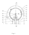
- the mill shown in Figures 1 and 2 comprises a rotary body 10 consisting of a short cylindrical shell 12 with a horizontal axis and a concentric ring 14 fixed inside the shell and constituting a grinding track.
- the body 10 is supported by a frame 16 on which it rests by means of a pad 18 located under the ring 14, which matches the shape of the ferrule and allows rotation around its axis.
- a lubrication system not shown, supplies, when the body 10 is rotated, pressurized oil to the bearing 18 so as to maintain, by hydrodynamic effect, an oil film between the sliding surfaces of the bearing and of the shell.
- the body 10 is rotated by a geared motor group, not shown, the output shaft of which carries a pinion 20 engaged with a ring gear 22 fixed on the ferrule.
- One of the ends of the ferrule is closed by a fixed wall 24 pierced with an opening to which a feed chute 26 is connected.
- the volume between the wall 24 and the ring constitutes an inlet chamber for the material to be ground which is centrifuged and brought inside the ring by a device described below.
- the other end opens into a casing 28 which is connected, at its upper part, to a pneumatic circuit allowing the evacuation of the fine fraction of the ground products, and the bottom of which collects the other fraction of the ground products and allows their evacuation through an airlock not shown.
- the pneumatic evacuation can be ensured by cooling air or by hot drying gases, when the material to grind contains moisture, sweeping the inside of the shell.
- the two fractions of the ground products are brought to separators where the finished product, having the desired particle size, is separated from the rejects which are recycled.
- a roller 30 is mounted inside the ring 14, above the frame 16 and rolls on the inside of the ring when the body 10 is rotated.
- the roller 30 is mounted idly on a shaft 32 parallel to the axis of the ring 14.
- the roller may have a cylindrical or slightly convex (curved) outer surface.
- the track surface can be cylindrical or slightly concave.
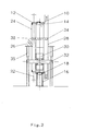
- This device consists of a fixed cross member 36 which extends from the wall 24 to the bottom of the casing 28 and which carries over its entire length blades 38 regularly spaced from one another and whose planes are parallel to each other and form an angle a with a plane perpendicular to the axis of the ferrule.
- the end of the blades is located a short distance from the surface of the ring 14, so that the blades penetrate into the layer of the ground products and, due to their inclination, ensure the displacement of the material parallel to the axis from the ferrule, from one edge to the other of the track.
- the blades located on either side of the ring allow, in the same way, to bring the products to be ground on the track and to evacuate the ground products.
- the distance, counted parallel to the axis of the ring, between the upstream edge and the downstream edge of each blade is a fraction of the width of the grinding track, so that, at each revolution of the ring, the material on the track is moved by the blades by a step equal to this fraction of the width of the track; it therefore passes several times between the roller and the ring and undergoes several grindings before being driven from the track and evacuated.
- the blades 38 are mounted on the crosspiece 36 so that it is possible to modify their orientation (angle a) and, consequently, to adjust the residence time of the material on the grinding track 14.
- the means allowing this setting, which can be remotely controlled, have not been shown.
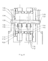
- the body 110 of the crusher is constituted by a cylindrical shell 112 inside which are mounted two rings 116 coated with wear plates 114 constituting two grinding tracks.
- the body 110 is supported by four pads 118, two under each ring, resting by means of ball joints on frames 120. These pads are lubricated in the same way as the bearing 18 of the first embodiment described above.
- a ring gear 122 fixed on the ferrule makes it possible to drive the mill in rotation.
- rollers 124 are mounted inside the shell so as to be able to roll on the tracks 114, when the mill is rotated. Each roller is located above a shoe 118.
- the rollers are mounted idly on their axes, and the axes of the rollers of each pair which roll on the same track, are fixed on a spreader 126 articulated on a beam 128 arranged longitudinally inside the shell and crossing it right through.
- the ends of the beam 128 are guided by slides integral with frames 130 or by levers articulated on these frames.
- Springs or jacks associated with a hydropneumatic system acting on the ends of the beam or on the levers make it possible to press the rollers on the tracks.
- the springs or jacks could be placed between the rollers and the spreaders or between these and the beam 128.
- a device 132 of the same design as the device 34, and provided with blades intended to ensure the advance of the material from one end to the other of the mill, is arranged in the upper half of the mill.
- the entry end of the shell is closed by a fixed wall 144 pierced with an opening for the passage of a feed chute 146 and its other end opens into a casing 148 through which the ground products are discharged.
- the crusher could be equipped with two feed chutes and two material advancement devices placed upstream, considering the direction of rotation of the crusher, of each roller.
- the rotary body of the mill could be supported by rollers.
- the roller or rollers could be driven in rotation, for example by means of a cardan extension, the ring or rings then being driven by friction.
- rollers could be diametrically opposite, their axes being located in the same vertical plane.
- the crusher shown in FIGS. 5 to 8 consists of a drum 210, with a horizontal axis, which is supported by two shoes 212 allowing its rotation about its axis; these skates could be replaced by a pad or pebbles.
- the drum is driven in rotation by conventional means, not shown, for example by a geared motor group the output shaft of which carries a pinion engaged with a ring gear fixed on the ferrule.
- the drum consists of a ferrule internally coated with wear plates which, in the central part, form an annular grinding track 214.
- the interior of the drum is thus divided into a feeding zone 211, a grinding zone 213 and an evacuation zone 215.
- a roller 216 is mounted inside the shell so as to roll on the track 214 when the drum 210 is rotated.
- This roller is mounted idle on a shaft, the ends of which are guided by vertical slides or by levers and are subjected to the action of springs or hydropneumatic jacks making it possible to press the roller on the grinding track with a predetermined and adjustable force. .
- This classic assembly is not shown in the drawings so as not to obscure them.
- the roller 216 At its end facing the inlet of the mill, the roller 216 has a reduced diameter portion 217 which makes it possible to crush the large pieces found in the materials to be ground before they reach the layer of the materials to be ground on which rolls the main part of the roller and, consequently, to improve the homogeneity of this layer and the efficiency of grinding.
- FIG. 9 show three examples of the application of this principle.
- the track 214a and the roller 216a each comprise two portions of different diameters, the portion on the inlet side of the mill having the largest diameter and an axial extent clearly smaller than the other portion; in the embodiment of FIG.
- the track 214b and the roller 216b each comprise a frustoconical portion, on the inlet side of the mill, and a cylindrical portion of greater axial extent; and FIG. 11 shows another embodiment in which the track 214 c and the roller 216 c are frustoconical, their largest diameter being on the side of the inlet of the mill.
- the arrow E indicates the direction of progression of the materials. It should be noted that this systematic grinding is only possible thanks to the step-by-step advance device which ensures progressive advance in the axial direction of the materials on the track.
- the drum In operation, the drum is rotated, in the direction of arrow R, at a speed greater than the critical speed, so that all the material is centrifuged and pressed on the inner surface of the drum, on its entire periphery.
- a device intended to ensure the advance of the material, from one end to the other of the drum, is arranged in the upper half of the drum, on the descending part of the circular trajectory of the materials.
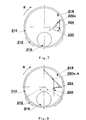
- This device consists of a fixed scraper 218 extending over the entire length of the drum and maintained in contact with or near its inner surface, and deflector plates 220 placed side by side, under the scraper, so as to intercept the flow materials detached from the drum by the latter.
- Each of the deflector plates is mounted on a support 222 so as to be able to pivot about a vertical axis 224 and a motor 226, such as a jack, to which the plate is connected by a connecting rod 228 makes it possible to control its rotation around this axis.
- These plates are inclined by about 45 ° and are arranged either as shown in FIG. 7 to deflect the materials detached by the scraper towards the axis of the drum, or as shown in FIG. 8 to bring the materials back to the shell.
- the device comprises three deflector plates: a plate 220a disposed in the upstream part of the drum which constitutes the supply zone 211, a plate 220 b disposed in the central part which constitutes the grinding zone 213, and a plate 220 c in the downstream part which constitutes the area for removing the ground material 215.
- the plates 220a and 220b are arranged so as to return the materials detached by the scraper towards the shell; the plate 220c is arranged so as to deflect the materials towards the axis of the drum.
- the number and arrangement of the deflector plates could be different depending on the dimensions of the mill and the results sought.
- Figure 6 shows the orientation of the deflector plates.
- the materials detached from the drum by the scraper 218 fall on the plates and slide thereon, along the lines of greatest slope, in the direction of the arrows P.
- the materials therefore advance at each revolution of the drum in a direction parallel to its axis and over a distance which is a fraction of the width (axial extent) of the track and which depends on the orientation of the deflector plates and is adjustable at will.
- the materials are thus brought step by step from the point of introduction into the feed zone on the grinding track, then moved to the grinding track and finally discharged at the desired speed.
- the orientation of the plates 220a, 220b and 220c being individually adjustable, it is possible to adopt different feed rates in the three zones of the mill.
- the advance at each revolution of the drum represents a fraction of the width of the track, so that the materials undergo several grindings before being discharged.
- the orientation of the deflector plates can be adjusted remotely and performed while the mill is running.
- the following table makes it possible to compare the quality of a cement obtained by grinding a clinker in a ring mill, according to the invention, to that of a standard cement (Cement CPA 425 - 95% clinker, 5% gypsum) conventionally ground in an installation equipped with a ball mill. It is noted that the invention makes it possible to obtain a cement of such good quality with a specific energy consumption 40% lower than that of a ball mill.
Landscapes
- Engineering & Computer Science (AREA)
- Food Science & Technology (AREA)
- Crushing And Grinding (AREA)
- Disintegrating Or Milling (AREA)
- Finish Polishing, Edge Sharpening, And Grinding By Specific Grinding Devices (AREA)
- Saccharide Compounds (AREA)
- Polishing Bodies And Polishing Tools (AREA)
- Crushing And Pulverization Processes (AREA)
Abstract
Description
- La présente invention a pour objet un procédé de broyage fin de matériaux tels que les matières premières pour la fabrication du ciment, le clinker, certains minerais, etc... Pour cette opération, on utilise communément des broyeurs tubulaires à boulets. Les broyeurs à meules verticaux conviennent aux broyage et séchage simultanés des matières premières mais pas au broyage du clinker car ils ne permettent pas d'obtenir du ciment de qualité satisfaisante. Les presses à cylindres sont essentiellement utilisées en prébroyage du clinker.
- Les broyeurs à boulets ont un très mauvais rendement énergétique, en particulier parce qu'ils ne permettent pas d'effectuer un broyage systématique, l'avancement de la matière dans le broyeur et l'action des boulets sur la matière étant incertains.
- Les broyeurs à meules verticaux ont un meilleur rendement de broyage. Cependant, pour obtenir la finesse désirée, on doit faire passer la matière sous les meules un grand nombre de fois. Pour cela, on équipe ces appareils de plusieurs meules, billes ou galets et on effectue un recyclage des produits dépassant généralement dix fois le débit nominal. Ces appareils qui comportent une multiplicité d'organes de broyage sont lourds et coûteux et la recirculation d'une grande quantité de matière, généralement par voie pneumatique, absorbe une quantité d'énergie importante qui annule en grande partie le gain d'énergie de broyage. Les broyeurs verticaux à galets pendulaires et horizontaux à anneau présentent les mêmes inconvénients que les broyeurs à meules.
- Les presses à cylindres, dans lesquelles la matière à broyer est soumise à une pression moyenne supérieure à 50 MPa en un seul passage, fournissent un produit prébroyé et aggloméré et, pour obtenir le produit à la finesse voulue, la matière prébroyée doit subir un broyage complémentaire dans un autre appareil tel qu'un broyeur à boulets. Dans ces appareils, l'agglomération de la matière due aux fortes pressions appliquées absorbe une partie de l'énergie en pure perte tandis que, à cause des pressions de broyage très élevées, les organes actifs, en particulier les paliers et les revêtements des cylindres, sont soumis à des contraintes mécaniques très importantes, nécessitant un entretien coûteux et des réparations fréquentes. Enfin son champ d'application est restreint au broyage des matières fragiles, très peu humides et pas trop abrasives.
- Le but de la présente invention est de proposer un procédé et un broyeur assurant un broyage systématique permettant d'augmenter le rendement énergétique en réduisant l'énergie nécessaire pour recycler la matière et de limiter les frais d'entretien et les risques d'arrêt pour réparation par l'emploi de pressions modérées.
- La présente invention a pour objet un procédé de broyage consistant à former une couche d'une matière à broyer sur une piste circulaire et à exercer une pression sur cette couche au moyen d'un rouleau apte à rouler sur la piste, caractérisé en ce que la pression moyenne exercée par le rouleau sur la matière en cours de broyage est comprise entre 10 et 40 MPa, et en ce que l'on contrôle le déplacement transversal de la matière, d'un bord à l'autre de la piste, de telle sorte que la matière passe plusieurs fois entre le rouleau et la piste de broyage avant de quitter cette dernière.
- La pression moyenne exercée par le rouleau sur la matière est le quotient de la force totale (poids + forces extérieures) appliquée au rouleau par la surface de la couche de matière sur laquelle s'exerce la pression du rouleau.
- L'invention a également pour objet un broyeur comportant une piste circulaire et au moins un rouleau apte à rouler sur la piste, caractérisé en ce qu'il comporte des moyens pour appliquer le rouleau sur la piste de broyage avec une force telle que le rouleau exerce sur la couche de matières recouvrant la piste une pression moyenne comprise entre 10 et 40 MPa, et en ce qu'un dispositif est prévu pour déplacer transversalement la matière sur la piste de broyage, sur une distance égale à une fraction seulement de la largeur de la piste à chaque tour de cette dernière.
- Avantageusement, le broyeur sera constitué par au moins un anneau rotatif à axe horizontal, au moins un rouleau placé à l'intérieur dudit anneau de façon à pouvoir rouler sur la piste constituée par la face intérieure de l'anneau, et des moyens pour entraîner l'anneau en rotation à une vitesse supérieure à la vitesse critique.
- Des essais de broyage de clinker effectués sur une installation pilote équipée d'un broyeur de ce type ont montré que la qualité du produit fini était comparable à celle du ciment obtenu avec un broyeur à boulets; les courbes granulométriques sont très voisines et les tests sur mortier et béton donnent des résultats égaux ou supérieurs. Par ailleurs, la consommation spécifique est inférieure d'environ 40 % à celle d'un broyeur à boulets et voisine de celle d'une presse à cylindres.
- Dans ce type de broyeur, le dispositif d'avance de la matière pourra avantageusement être constitué par un jeu de pales dont la largeur, comptée parallèlement à l'axe de l'anneau, est une fraction de la largeur de la piste, dont les plans font un angle avec un plan perpendiculaire à l'axe de l'anneau et qui sont diposés de façon à pénétrer dans la couche de matière retenue sur la piste par la force centrifuge lorsque l'anneau est en rotation.
- Le dispositif pourra aussi être constitué par un racleur s'étendant parallèlement à l'axe de l'anneau et pénétrant dans la couche des matières retenues sur la piste de broyage par la force centrifuge pour l'en détacher, et par des plaques déflectrices disposées sous le racleur et orientées de façon à intercepter les matières détachées par le racleur et à les dévier vers la sortie du broyeur. Chaque plaque déflectrice sera montée de façon à pouvoir pivoter autour d'un axe, de préférence vertical, et sera inclinée, par exemple de 45°, soit de façon à dévier les matières vers l'axe de l'anneau, soit au contraire de façon à ramener les matières vers la piste de broyage. Des moyens de commande permettront de modifer l'orientation des plaques déflectrices pour régler la vitesse d'avance des matières sur la piste de broyage. Ce dispositif d'avance pas à pas des matières permet, en faisant tomber les matières en pluie de l'anneau sur les plaques déflectrices, l'extraction pneumatique des fines particules et le séchage des matières au moyen d'un courant d'air, éventuellement chaud, circulant à l'intérieur du broyeur.
- L'anneau pourra être fixé sur une virole cylindrique coaxiale formant, en amont de l'anneau une chambre d'admission pour la matière à broyer qui y est centrifugée, et le dispositif d'avance de la matière sera conçu pour amener la matière de la chambre d'admission sur la piste de broyage de l'anneau.
- On pourra éventuellement prévoir deux rouleaux angulairement espacés l'un de l'autre à l'intérieur de l'anneau et associer à chaque rouleau un dispositif d'avance de la matière.
- On pourra aussi prévoir, à l'intérieur d'une virole cylindrique à axe horizontal, plusieurs anneaux axialement espacés l'un de l'autre, et à l'intérieur de chaque anneau un ou plusieurs rouleaux.
- Suivant une autre caractéristique de l'invention, le diamètre du rouleau et/ou de la piste de broyage varient progressivement ou par degrés d'une extrémité à l'autre du rouleau et/ou d'un bord à l'autre de la piste, respectivement, de telle sorte que l'écartement entre le rouleau et la piste décroisse progressivement ou par degrés de l'entrée vers la sortie de la zone de broyage. On pourra, par exemple, utiliser une piste cylindrique et un rouleau formé de deux parties ou plus de diamètres différents ou un rouleau tronconique, l'extrémité de petit diamètre du rouleau étant tournée vers l'entrée du broyeur. On pourra aussi utiliser une piste à plusieurs diamètres ou tronconique coopérant avec un rouleau cylindrique, tronconique ou étagé. Une disposition particulièrement avantageuse consiste à réaliser la piste et le rouleau de telle sorte que le rapport des diamètres de la piste et du rouleau soit le même dans toutes les sections afin qu'il ne se produise pas de glissement relatif entre les surfaces conjuguées. La piste et le rouleau auront une forme tronconique ou comporteront plusieurs portions cylindriques avec la portion de plus grand diamètre tournée vers l'entrée du broyeur.
- Cette caractéristique combinée avec l'usage du dispositif d'avance pas à pas des matières permet de réaliser un broyage systématique dans des conditions optimales des produits à granulométrie hétérogène.
- D'autres caractéristiques de l'invention apparaîtront à la lecture de la description qui suit et se réfère aux dessins l'accompagnant qui montrent, à titre d'exemple non limitatif, deux formes de réalisation de l'invention et sur lesquels :
- - La figure 1 est une vue en élévation d'un broyeur à anneau conforme à l'invention, le carter côté sortie ayant été enlevé pour montrer l'intérieur de l'anneau;
- - La figure 2 est une coupe suivant A-A du broyeur de la figure 1;
- - La figure 3 est une vue en élévation d'un autre broyeur conforme à l'invention;
- - La figure 4 est une coupe suivant B-B du broyeur de la figure 3;
- - La figure 5 est une représentation schématique, en coupe verticale, d'un broyeur conforme à l'invention, équipé d'un rouleau étagé et d'un dispositif d'avance de la matière à plaques déflectrices.
- - La figure 6 est une vue schématique, en plan, montrant l'orientation des plaques déflectrices;
- - La figure 7 est une vue suivant F du broyeur de la figure 5;
- - La figure 8 est une coupe suivant C-C du broyeur de la figure 1; et
- - Les figures 9 à 11 sont des vues en coupe verticale illustrant des variantes de réalisation.
- Le broyeur représenté sur les figures 1 et 2 comporte un corps rotatif 10 constitué par une courte virole cylindrique 12 à axe horizontal et un anneau concentrique 14 fixé à l'intérieur de la virole et constituant une piste de broyage.
- Le corps 10 est supporté par un bâti 16 sur lequel il repose par l'intermédiaire d'un coussinet 18 situé sous l'anneau 14, qui épouse la forme de la virole et permet la rotation autour de son axe. Un système de lubrification, non représenté, fournit, lorsque le corps 10 est entraîné en rotation, de l'huile sous pression au coussinet 18 de façon à maintenir, par effet hydrodynamique, un film d'huile entre les surfaces de glissement du coussinet et de la virole.
- Le corps 10 est entraîné en rotation par un groupe moto-réducteur, non représenté, dont l'arbre de sortie porte un pignon 20 en prise avec une couronne dentée 22 fixée sur la virole.
- L'une des extrémités de la virole est fermée par une paroi fixe 24 percée d'une ouverture à laquelle est raccordée une goulotte d'alimentation 26. Le volume compris entre la paroi 24 et l'anneau constitue une chambre d'admission pour la matière à broyer qui est centrifugée et amenée à l'intérieur de l'anneau par un dispositif décrit ci-après. L'autre extrémité débouche dans un carter 28 qui est relié, à sa partie supérieure, à un circuit pneumatique permettant l'évacuation de la fraction fine des produits broyés, et dont le fond recueille l'autre fraction des produits broyés et permet leur évacuation à travers un sas non représenté. L'évacuation pneumatique pourra être assurée par de l'air de refroidissement ou par des gaz chauds de séchage, lorsque la matière à broyer contient de l'humidité, balayant l'intérieur de la virole. Les deux fractions des produits broyés sont amenées à des séparateurs où le produit fini, ayant la granulométrie voulue, est séparé des refus qui sont recyclés.
- Un rouleau 30 est monté à l'intérieur de l'anneau 14, au-dessus du bâti 16 et roule sur la face intérieure de l'anneau lorsque le corps 10 est entraîné en rotation. Le rouleau 30 est monté fou sur un arbre 32 parallèle à l'axe de l'anneau 14.
- Les extrémités de l'arbre 32, qui sont à l'extérieur de la virole, sont guidées par des glissières verticales 33 solidaires du bâti 16 ou par des leviers articulés sur ce bâti. Des ressorts ou des vérins 35 associés à un système hydropneumatique permettent d'exercer sur les extrémités de l'arbre des efforts qui sont transmis au rouleau et pressent ce dernier sur l'anneau 14. Des moyens classiques sont prévus pour régler les efforts exercés par les ressorts ou les vérins.
- Le rouleau peut avoir une surface extérieure cylindrique ou légèrement convexe (bombée). La surface de la piste peut être cylindrique ou légèrement concave.
- Un dispositif 34 destiné à assurer l'avance des produits, d'une extrémité à l'autre de la virole 12, est disposé dans la moitié supérieure du corps 10, sur la partie descendante de la trajectoire circulaire suivie par les produits broyés maintenus sur la piste 14 par la force centrifuge. Ce dispositif est constitué par une traverse fixe 36 qui s'étend de la paroi 24 au fond du carter 28 et qui porte sur toute sa longueur des pales 38 régulièrement espacées l'une de l'autre et dont les plans sont parallèles entre eux et forment un angle a avec un plan perpendiculaire à l'axe de la virole. L'extrémité des pales se trouve à faible distance de la surface de l'anneau 14, de sorte que les pales pénètrent dans la couche des produits broyés et, du fait de leur inclinaison, assurent le déplacement de la matière parallèlement à l'axe de la virole, d'un bord à l'autre de la piste. Les pales se trouvant de part et d'autre de l'anneau permettent, de la même manière, d'amener les produits à broyer sur la piste et d'évacuer les produits broyés.
- La distance, comptée parallèlement à l'axe de l'anneau, entre le bord amont et le bord aval de chaque pale est une fraction de la largeur de la piste de broyage, de sorte que, à chaque tour de l'anneau, la matière se trouvant sur la piste est déplacée par les pales d'un pas égal à cette fraction de la largeur de la piste; elle passe donc plusieurs fois entre le rouleau et l'anneau et subit plusieurs broyages avant d'être chassée de la piste et évacuée.
- Les pales 38 sont montées sur la traverse 36 de telle sorte qu'il soit possible de modifier leur orientation (angle a) et, par conséquent, de régler le temps de séjour de la matière sur la piste de broyage 14. Les moyens permettant ce réglage, qui peuvent être télécommandés, n'ont pas été représentés.
- Dans la forme de réalisation représentée sur les figures 3 et 4, le corps 110 du broyeur est constitué par une virole cylindrique 112 à l'intérieur de laquelle sont montés deux anneaux 116 revêtus de plaques d'usure 114 constituant deux pistes de broyage. Le corps 110 est supporté par quatre patins 118, deux sous chaque anneau, reposant par l'intermédiaire de rotules sur des bâtis 120. Ces patins sont lubrifiés de la même manière que le coussinet 18 de la première forme de réalisation décrite ci-dessus. Une couronne dentée 122 fixée sur la virole permet d'entraîner le broyeur en rotation.
- Quatre rouleaux 124 sont montés à l'intérieur de la virole de façon à pouvoir rouler sur les pistes 114, lorsque le broyeur est entraîné en rotation. Chaque rouleau est situé au-dessus d'un patin 118. Les rouleaux sont montés fous sur leurs axes, et les axes des rouleaux de chaque paire qui roulent sur une même piste, sont fixés sur un palonnier 126 articulé sur une poutre 128 disposée longitudinalement à l'intérieur de la virole et la traversant de part en part. Les extrémités de la poutre 128 sont guidées par des glissières solidaires de bâtis 130 ou par des leviers articulés sur ces bâtis. Des ressorts ou des vérins associés à un système hydropneumatique agissant sur les extrémités de la poutre ou sur les leviers permettent de presser les rouleaux sur les pistes. En variante, les ressorts ou vérins pourraient être placés entre les rouleaux et les palonniers ou entre ceux-ci et la poutre 128.
- Un dispositif 132, de même conception que le dispositif 34, et muni de pales destinées à assurer l'avance de la matière d'une extrémité à l'autre du broyeur, est disposé dans la moitié supérieure du broyeur.
- L'extrémité d'entrée de la virole est fermée par une paroi fixe 144 percée d'une ouverture pour le passage d'une goulotte d'alimentation 146 et son autre extrémité débouche dans un carter 148 à travers lequel les produits broyés sont évacués.
- En variante, le broyeur pourrait être équipé de deux goulottes d'alimentation et de deux dispositifs d'avancement de la matière placées en amont, en considérant le sens de rotation du broyeur, de chaque rouleau.
- Au lieu d'être supporté par un coussinet ou des patins le corps rotatif du broyeur pourrait être supporté par des galets. On pourrait entraîner le ou les rouleaux en rotation, par exemple au moyen d'une allonge à cardans, l'anneau ou les anneaux étant alors entraînés par friction.
- Les galets pourraient être diamétralement opposés, leurs axes étant situés dans un même plan vertical.
- Le broyeur représenté sur les figures 5 à 8 est constitué par un tambour 210, à axe horizontal, qui est supporté par deux patins 212 permettant sa rotation autour de son axe; ces patins pourraient être remplacés par un coussinet ou des galets. Le tambour est entraîné en rotation par des moyens classiques, non représentés, par exemple par un groupe moto-réducteur dont l'arbre de sortie porte un pignon en prise avec une couronne dentée fixée sur la virole.
- Le tambour est constitué par une virole revêtue intérieurement de plaques d'usure qui, dans la partie centrale, forment une piste de broyage annulaire 214. L'intérieur du tambour est ainsi divisé en une zone d'alimentation 211, une zone de broyage 213 et une zone d'évacuation 215.
- Un rouleau 216 est monté à l'intérieur de la virole de façon à rouler sur la piste 214 lorsque le tambour 210 est entraîné en rotation. Ce rouleau est monté fou sur un arbre dont les extrémités sont guidées par des glissières verticales ou par des leviers et sont soumises à l'action de ressorts ou de vérins hydropneumatiques permettant de presser le rouleau sur la piste de broyage avec une force prédéterminée et réglable. Ce montage classique n'est pas représenté sur les dessins pour ne pas les obscurcir.
- On pourrait utiliser plusieurs rouleaux disposés à l'intérieur de l'angle d'appui β du tambour délimité par les patins 212. Dans le cas où le tambour est supporté par un coussinet, cet angle est celui de la portée du coussinet.
- A son extrémité tournée vers l'entrée du broyeur, le rouleau 216 comporte une partie de diamètre réduit 217 qui permet d'écraser les gros morceaux se trouvant dans les matières à broyer avant qu'elles n'atteignent la couche des matières à broyer sur laquelle roule la partie principale du rouleau et, par conséquent, d'améliorer l'homogéneité de cette couche et l'efficacité du broyage.
- Dans le même esprit, on pourra, dans le cas de matières à granulométrie très hétérogène, réaliser un broyage systématique en utilisant un rouleau étagé formé de plusieurs portions de diamètres croissants de l'entrée vers la sortie ou, à la limite, un rouleau tronconique dont le petit diamètre se trouverait côté entrée et le grand diamètre côté sortie. Le même résultat pourrait être atteint en utilisant un rouleau cylindrique et une piste de broyage étagée ou tronconique avec son plus grand diamètre côté entrée et son petit diamètre côté sortie. En utilisant ensemble une piste et un rouleau étagés ou tronconiques, présentant dans chaque section droite, perpendiculaire à l'axe du broyeur, un rapport constant entre les diamètres de la piste et du rouleau, l'écrasement des gros morceaux et de la couche à broyer s'effectue sans cisaillement ni glissement relatif qui sont des facteurs d'usure des surfaces de travail de la piste et du rouleau. Les figures 9 à 11 montrent trois exemples d'application de ce principe. Sur la figure 9, la piste 214a et le rouleau 216a comportent chacun deux portions de diamètres différents, la portion côté entrée du broyeur ayant le plus grand diamètre et une étendue axiale nettement inférieure à l'autre portion; dans la forme de réalisation de la figure 10, la piste 214b et le rouleau 216b comportent chacun une portion tronconique, côté entrée du broyeur, et une portion cylindrique de plus grande étendue axiale; et la figure 11 montre une autre forme de réalisation dans laquelle la piste 214 c et le rouleau 216 c sont tronconiques, leur plus grand diamètre se trouvant du côté de l'entrée du broyeur. Sur ces figures, la flèche E indique le sens de progression des matières. Il faut noter que ce broyage systématique n'est possible que grâce au dispositif d'avance pas à pas qui assure une avance progressive dans la direction axiale des matières sur la piste.
- En fonctionnement, le tambour est entraîné en rotation, dans le sens de la flèche R, à une vitesse supérieure à la vitesse critique, de telle sorte que toute la matière soit centrifugée et plaquée sur la surface intérieure du tambour, sur toute sa périphérie.
- Un dispositif destiné à assurer l'avance de la matière, d'une extrémité à l'autre du tambour, est disposé dans la moitié supérieure du tambour, sur la partie descendante de la trajectoire circulaire des matières.
- Ce dispositif est constitué par un racleur fixe 218 s'étendant sur toute la longueur du tambour et maintenu au contact ou à proximité de sa surface intérieure, et des plaques déflectrices 220 disposées côte à côte, sous le racleur, de façon à intercepter le flot des matières détachées du tambour par ce dernier.
- Chacune des plaques déflectrices est montée sur un support 222 de façon à pouvoir pivoter autour d'un axe vertical 224 et un moteur 226, tel qu'un vérin, auquel la plaque est reliée par une bielle 228 permet de commander sa rotation autour de cet axe.
- Ces plaques sont inclinées d'environ 45° et sont disposées soit comme représenté sur la figure 7 pour dévier les matières détachées par le racleur vers l'axe du tambour, soit comme représenté sur la figure 8 pour ramener les matières vers la virole.
- Dans la forme de réalisation représentée sur le dessin, le dispositif comporte trois plaques déflectrices : une plaque 220a disposée dans la partie amont du tambourqui constitue la zône d'alimentation 211, une plaque 220 b disposée dans la partie centrale qui constitue la zone de broyage 213, et une plaque 220 c dans la partie aval qui constitue la zone d'évacuation des matières broyés 215. Les plaques 220a et 220b sont disposées de façon à renvoyer les matières détachées par le racleur vers la virole; la plaque 220c est disposée de façon à dévier les matières vers l'axe du tambour.
- Le nombre et la disposition des plaques déflectrices pourraient être différents suivant les dimensions du broyeur et les résultats recherchés.
- La figure 6 montre l'orientation des plaques déflectrices. Les matières détachées du tambour par le racleur 218 tombent sur les plaques et glissent sur celles-ci, le long des lignes de plus grande pente, dans la direction des flèches P. Les matières avancent donc à chaque tour du tambour dans une direction parallèle à son axe et sur une distance qui est une fraction de la largeur (étendue axiale) de la piste et qui dépend de l'orientation des plaques déflectrices et est réglable à volonté. Les matières sont ainsi amenées pas à pas du point d'introduction dans la zone d'alimentation juque sur la piste de broyage, puis déplacées sur la piste de broyage et enfin évacuées à la vitesse voulue. L'orientation des plaques 220a, 220b et 220c étant réglable individuellement, il est possible d'adopter des vitesses d'avance différentes dans les trois zones du broyeur.
- Dans la zone de broyage, l'avance à chaque tour du tambour représente une fraction de la largeur de la piste, de sorte que les matières subissent plusieurs broyages avant d'être évacuées.
- Le réglage de l'orientation des plaques déflectrices peut être télécommandé et effectué pendant la marche du broyeur.
- Le tableau suivant permet de comparer la qualité d'un ciment obtenu par broyage d'un clinker dans un broyeur à anneau, suivant l'invention, à celle d'un ciment standard (Ciment CPA 425 - 95 % clinker, 5% gypse) broyé de façon classique dans une installation équipée d'un broyeur à boulets. On constate que l'invention permet d'obtenir un ciment d'aussi bonne qualité avec une consommation d'énergie spécifique inférieure de 40 % à celle d'un broyeur à boulets.


Claims (12)
Applications Claiming Priority (4)
| Application Number | Priority Date | Filing Date | Title |
|---|---|---|---|
| FR9014004A FR2668952A1 (fr) | 1990-11-12 | 1990-11-12 | Procede de broyage et broyeur a anneau pour la mise en óoeuvre de ce procede. |
| FR9014004 | 1990-11-12 | ||
| FR9109788A FR2679792B1 (fr) | 1991-08-01 | 1991-08-01 | Perfectionnements aux broyeurs a anneaux. |
| FR9109788 | 1991-08-01 |
Publications (4)
| Publication Number | Publication Date |
|---|---|
| EP0486371A2 true EP0486371A2 (fr) | 1992-05-20 |
| EP0486371A3 EP0486371A3 (fr) | 1992-06-03 |
| EP0486371B1 EP0486371B1 (fr) | 1996-06-05 |
| EP0486371B2 EP0486371B2 (fr) | 2001-07-25 |
Family
ID=26228324
Family Applications (1)
| Application Number | Title | Priority Date | Filing Date |
|---|---|---|---|
| EP91402999A Expired - Lifetime EP0486371B2 (fr) | 1990-11-12 | 1991-11-07 | Broyeur pour la broyage fin de matériaux |
Country Status (14)
| Country | Link |
|---|---|
| US (1) | US5205494A (fr) |
| EP (1) | EP0486371B2 (fr) |
| JP (1) | JP2554804B2 (fr) |
| AT (1) | ATE138832T1 (fr) |
| CA (1) | CA2055227C (fr) |
| CZ (1) | CZ287037B6 (fr) |
| DE (1) | DE69120027T3 (fr) |
| DK (1) | DK0486371T4 (fr) |
| ES (1) | ES2087267T5 (fr) |
| GR (1) | GR3020457T3 (fr) |
| MX (1) | MX9102005A (fr) |
| PL (1) | PL167824B1 (fr) |
| RU (1) | RU2040968C1 (fr) |
| SK (1) | SK280804B6 (fr) |
Cited By (16)
| Publication number | Priority date | Publication date | Assignee | Title |
|---|---|---|---|---|
| FR2695841A1 (fr) * | 1992-09-24 | 1994-03-25 | Buzzi Flli Spa | Broyeur à piste annulaire et rouleau et plaques d'usure pour de tels broyeurs. |
| WO1995017967A1 (fr) * | 1993-12-27 | 1995-07-06 | Italcementi S.P.A. | Broyeur tubulaire destine a broyer des matieres premieres naturelles et synthetiques, en particulier pour l'industrie du ciment |
| WO1997002093A1 (fr) * | 1995-07-04 | 1997-01-23 | F.L. Smidth & Co. A/S | Broyeur a cylindres annulaires |
| FR2747598A1 (fr) * | 1996-04-23 | 1997-10-24 | Fcb | Procede de broyage en voie humide et broyeur pour la mise en oeuvre de ce procede |
| EP0829303A1 (fr) * | 1996-09-13 | 1998-03-18 | DEUTZ Aktiengesellschaft | Broyeur à anneau et rouleau pour le broyage par pression de matériau granulé |
| EP0858839A1 (fr) * | 1997-02-18 | 1998-08-19 | Kawasaki Jukogyo Kabushiki Kaisha | Procédé et dispositif de broyage de clinker de ciment au moyen d'un broyeur vertical à rouleaux |
| WO2003045562A1 (fr) * | 2001-09-17 | 2003-06-05 | Zhigang Hao | Broyeur a cylindre et rouleaux |
| WO2011064461A1 (fr) * | 2009-11-25 | 2011-06-03 | Solios Carbone | Procédé et machine de fabrication de pâte, notamment de pâte carbonée pour la réalisation d'électrodes de production d'aluminium |
| WO2011117482A1 (fr) | 2010-03-25 | 2011-09-29 | Fives Fcb | Palier hydrodynamique destiné à soutenir un cylindre animé d'un mouvement de rotation autour de son axe |
| WO2011151534A1 (fr) | 2010-05-05 | 2011-12-08 | Fives Fcb | Procede et installation de broyage d'une matiere minerale contenant au moins du calcium et des impuretes metalliques |
| WO2013079883A1 (fr) | 2011-12-02 | 2013-06-06 | Fives Fcb | Broyeur par compression de lit de matières |
| WO2014064243A1 (fr) | 2012-10-26 | 2014-05-01 | Lafarge | Processus, unité de broyage et production d'un liant hydraulique |
| WO2016055734A1 (fr) | 2014-10-10 | 2016-04-14 | Fives Fcb | Broyeur par compression de lit de matières |
| CN106732964A (zh) * | 2017-01-06 | 2017-05-31 | 泉州台商投资区尚良建筑装饰有限公司 | 一种高效的耐火材料生产用的碾压粉碎设备 |
| US11396022B2 (en) | 2018-08-28 | 2022-07-26 | Canada Mining Innovation Council | Mono roller grinding mill |
| WO2024227698A1 (fr) * | 2023-05-02 | 2024-11-07 | Elkano | Dispositif de broyage d'un produit pateux ou en poudre et en suspension |
Families Citing this family (13)
| Publication number | Priority date | Publication date | Assignee | Title |
|---|---|---|---|---|
| RU2179888C2 (ru) * | 1997-04-15 | 2002-02-27 | Фсб | Устройство для поступательной подачи материала для дробилки |
| UA48227C2 (uk) * | 1997-04-15 | 2002-08-15 | Фсб | Пристрій для прямої подачі матеріалу до подрібнювача барабанного типу |
| PT1078107E (pt) * | 1998-04-22 | 2003-07-31 | Anglo American Resear Lbrt Pro | Processo de fragmentacao de minerio usando um metodo de compressao de leito a pressoes baixas e instalacao para esse fim |
| DE10259541A1 (de) * | 2002-12-19 | 2004-07-08 | Khd Humboldt Wedag Ag | Kreislaufmahleinrichtung mit Mühle und Sichter |
| RU2345838C2 (ru) * | 2004-07-28 | 2009-02-10 | Евгений Дмитриевич Верич | Способ измельчения материала и устройство для его осуществления |
| CN101041144B (zh) * | 2007-03-13 | 2011-04-27 | 江苏科行环境工程技术有限公司 | 一种卧辊磨 |
| RU2497594C1 (ru) * | 2012-06-08 | 2013-11-10 | Федеральное государственное бюджетное образовательное учреждение высшего профессионального образования "Белгородский государственный технологический университет им. В.Г. Шухова" | Горизонтальная валковая мельница |
| CN103816962A (zh) * | 2014-03-08 | 2014-05-28 | 齐玉民 | 自转滚筒内的多辊碾磨机装置 |
| CN106622499A (zh) * | 2016-12-27 | 2017-05-10 | 中冶南方工程技术有限公司 | 一种钢渣卧辊磨除铁装置及其除铁方法 |
| CN111521381B (zh) * | 2020-04-28 | 2022-01-18 | 广东电网有限责任公司东莞供电局 | 贮能位移测量装置 |
| CN113457792B (zh) * | 2021-07-20 | 2022-06-21 | 天津水泥工业设计研究院有限公司 | 一种立式辊磨选粉机回料控制装置设计方法 |
| CN113559975B (zh) * | 2021-07-30 | 2022-08-09 | 王予安 | 一种药片多规格研磨装置及其使用方法 |
| CN118060042B (zh) * | 2024-04-17 | 2024-07-02 | 邢台路桥建设集团有限公司 | 赤泥建材充填料破碎混合设备 |
Family Cites Families (17)
| Publication number | Priority date | Publication date | Assignee | Title |
|---|---|---|---|---|
| DE249567C (fr) * | ||||
| DE205481C (fr) * | ||||
| US2282887A (en) * | 1942-05-12 | Wood grinding machine | ||
| FR471647A (fr) * | 1914-03-27 | 1914-11-05 | Paul Dirand | Moulin broyeur à axe horizontal avec palettes à inclinaison variable |
| DE345915C (de) * | 1919-08-05 | 1921-12-20 | E C Loesche | Ringwalzenmuehle mit umlaufendem Mahlring und nachgiebig gelagerten, radial beweglichen, gegen die Innenflaeche des Ringes gepressten Mahlwalzen |
| GB362327A (en) * | 1931-05-28 | 1931-12-03 | Toussaint Ketin | Improvements in grinding apparatus |
| DE548555C (de) † | 1931-06-02 | 1932-04-14 | Toussaint Ketin | Vorrichtung zum Auflockern, Vorschieben und Austragen des Mahlgutes bei Rohrmuehlen u. dgl. |
| DE596858C (de) † | 1932-06-03 | 1934-05-11 | Karl Querfurth | Verfahren zum Getriebe von Rohrmuehlen, die mit hoher Umdrehungszahl laufen |
| DE667011C (de) † | 1936-04-07 | 1938-11-07 | Hermann Hildebrandt | Ringwalzenmuehle zum Vermahlen, Verreiben, Mischen o. dgl. von Gut jeder Art und Form |
| US2748667A (en) * | 1953-07-16 | 1956-06-05 | Roswell F Taylor | Apparatus for grinding and refining material |
| US2875955A (en) * | 1956-09-13 | 1959-03-03 | Appleton Mach | Wood grinding machine |
| FR2385938A1 (fr) * | 1977-03-30 | 1978-10-27 | Fives Cail Babcock | Dispositif de lubrification pour paliers a patins supportant une piece tournante de grand diametre, telle qu'un broyeur rotatif |
| US4373674A (en) * | 1979-02-14 | 1983-02-15 | Marion Barrera | Crushing method and apparatus |
| IT1153927B (it) * | 1982-12-28 | 1987-01-21 | Italcementi Spa | Molino tubolare per la macinazione di materie prime naturali e sintetiche, in particolare per l'industria del cemento |
| DE3640081A1 (de) * | 1986-11-24 | 1988-06-01 | Rieter Werke Haendle | Kollergang |
| DE3705050A1 (de) * | 1987-02-18 | 1988-09-01 | Kloeckner Humboldt Deutz Ag | Zweiwalzenmaschine wie z.b. walzenpresse |
| JPS644262A (en) * | 1987-06-24 | 1989-01-09 | Ishikawajima Harima Heavy Ind | Horizontal multistage roller mill |
-
1991
- 1991-11-07 DK DK91402999T patent/DK0486371T4/da active
- 1991-11-07 DE DE69120027T patent/DE69120027T3/de not_active Expired - Lifetime
- 1991-11-07 AT AT91402999T patent/ATE138832T1/de not_active IP Right Cessation
- 1991-11-07 ES ES91402999T patent/ES2087267T5/es not_active Expired - Lifetime
- 1991-11-07 EP EP91402999A patent/EP0486371B2/fr not_active Expired - Lifetime
- 1991-11-08 CA CA002055227A patent/CA2055227C/fr not_active Expired - Lifetime
- 1991-11-08 US US07/790,666 patent/US5205494A/en not_active Expired - Lifetime
- 1991-11-11 MX MX9102005A patent/MX9102005A/es unknown
- 1991-11-11 RU SU915010161A patent/RU2040968C1/ru active
- 1991-11-11 SK SK3414-91A patent/SK280804B6/sk not_active IP Right Cessation
- 1991-11-11 CZ CS19913414A patent/CZ287037B6/cs not_active IP Right Cessation
- 1991-11-12 PL PL91292358A patent/PL167824B1/pl unknown
- 1991-11-12 JP JP3295533A patent/JP2554804B2/ja not_active Expired - Lifetime
-
1996
- 1996-07-03 GR GR960401830T patent/GR3020457T3/el unknown
Cited By (37)
| Publication number | Priority date | Publication date | Assignee | Title |
|---|---|---|---|---|
| EP0589774A1 (fr) * | 1992-09-24 | 1994-03-30 | F C B S.A. | Broyeur à piste annulaire et rouleau et plaques d'usure pour de tels broyeurs |
| FR2695841A1 (fr) * | 1992-09-24 | 1994-03-25 | Buzzi Flli Spa | Broyeur à piste annulaire et rouleau et plaques d'usure pour de tels broyeurs. |
| US5743475A (en) * | 1993-12-27 | 1998-04-28 | Italcementi S.P.A. | Tubular mill for grinding natural and synthetic raw materials in particular for the cement industry |
| WO1995017967A1 (fr) * | 1993-12-27 | 1995-07-06 | Italcementi S.P.A. | Broyeur tubulaire destine a broyer des matieres premieres naturelles et synthetiques, en particulier pour l'industrie du ciment |
| WO1997002093A1 (fr) * | 1995-07-04 | 1997-01-23 | F.L. Smidth & Co. A/S | Broyeur a cylindres annulaires |
| RU2140821C1 (ru) * | 1995-07-04 | 1999-11-10 | Ф.Л. Смидт Энд Ко. А/С | Способ измельчения материала в кольцевой роликовой мельнице |
| WO1997039829A1 (fr) * | 1996-04-23 | 1997-10-30 | Fcb | Procede de broyage en voie humide et broyeur pour la mise en oeuvre de ce procede |
| FR2747598A1 (fr) * | 1996-04-23 | 1997-10-24 | Fcb | Procede de broyage en voie humide et broyeur pour la mise en oeuvre de ce procede |
| US6179233B1 (en) * | 1996-04-23 | 2001-01-30 | Fcb Societe Anonyme | Wet crushing process and crusher for implementing such process |
| DE19637274A1 (de) * | 1996-09-13 | 1998-03-19 | Deutz Ag | Ringwalzenmühle zur Druckzerkleinerung körnigen Gutmaterials |
| EP0829303A1 (fr) * | 1996-09-13 | 1998-03-18 | DEUTZ Aktiengesellschaft | Broyeur à anneau et rouleau pour le broyage par pression de matériau granulé |
| EP0858839A1 (fr) * | 1997-02-18 | 1998-08-19 | Kawasaki Jukogyo Kabushiki Kaisha | Procédé et dispositif de broyage de clinker de ciment au moyen d'un broyeur vertical à rouleaux |
| US6193176B1 (en) | 1997-02-18 | 2001-02-27 | Kawasaki Jukogyo Kabushiki Kaisha | Cement clinker grinding method using vertical roller mill and apparatus |
| WO2003045562A1 (fr) * | 2001-09-17 | 2003-06-05 | Zhigang Hao | Broyeur a cylindre et rouleaux |
| US7118057B2 (en) | 2001-09-17 | 2006-10-10 | Zhigang Hao | Horizontal roller mill |
| WO2011064461A1 (fr) * | 2009-11-25 | 2011-06-03 | Solios Carbone | Procédé et machine de fabrication de pâte, notamment de pâte carbonée pour la réalisation d'électrodes de production d'aluminium |
| US9010670B2 (en) | 2009-11-25 | 2015-04-21 | Fives Solios S.A. | Method and machine for manufacturing paste, in particular carbon paste for making aluminum production electrodes |
| US9713882B2 (en) | 2009-11-25 | 2017-07-25 | Fives Solios S.A. | Method and machine for manufacturing paste, in particular carbon paste for making aluminum production electrodes |
| WO2011117482A1 (fr) | 2010-03-25 | 2011-09-29 | Fives Fcb | Palier hydrodynamique destiné à soutenir un cylindre animé d'un mouvement de rotation autour de son axe |
| FR2957994A1 (fr) * | 2010-03-25 | 2011-09-30 | Fives Fcb | Palier hydrodynamique destine a soutenir un cylindre anime d'un mouvement de rotation autour de son axe |
| CN102803762A (zh) * | 2010-03-25 | 2012-11-28 | 菲弗斯有限公司 | 用于支撑被驱动围绕其轴线转动的圆筒的流体动力轴承 |
| US9140295B2 (en) | 2010-03-25 | 2015-09-22 | Fives Fcb | Hydrodynamic bearing intended to support a cylinder driven in rotation about its axis |
| CN102803762B (zh) * | 2010-03-25 | 2015-08-19 | 菲弗斯有限公司 | 用于支撑被驱动围绕其轴线转动的圆筒的流体动力轴承 |
| WO2011151534A1 (fr) | 2010-05-05 | 2011-12-08 | Fives Fcb | Procede et installation de broyage d'une matiere minerale contenant au moins du calcium et des impuretes metalliques |
| US10569277B2 (en) | 2010-05-05 | 2020-02-25 | Fives Fcb | Method of grinding a mineral material containing at least calcium and metal impurities, and plant suitable for grinding a mineral material containing calcium and metal impurities as they stand |
| WO2013079883A1 (fr) | 2011-12-02 | 2013-06-06 | Fives Fcb | Broyeur par compression de lit de matières |
| US9675977B2 (en) | 2011-12-02 | 2017-06-13 | Fives Fcb | Compressive grinder for a bed of materials |
| WO2014064243A1 (fr) | 2012-10-26 | 2014-05-01 | Lafarge | Processus, unité de broyage et production d'un liant hydraulique |
| FR2997319A1 (fr) * | 2012-10-26 | 2014-05-02 | Lafarge Sa | Procede, ensemble de broyage et fabrication d'un liant hydraulique |
| CN107107066B (zh) * | 2014-10-10 | 2020-05-05 | 法孚斯弗克布公司 | 通过压缩粉碎料层的磨机 |
| CN107107066A (zh) * | 2014-10-10 | 2017-08-29 | 法孚斯弗克布公司 | 通过压缩粉碎料层的磨机 |
| US10589281B2 (en) | 2014-10-10 | 2020-03-17 | Fives Fcb | Mill for crushing a bed of materials by compression |
| WO2016055734A1 (fr) | 2014-10-10 | 2016-04-14 | Fives Fcb | Broyeur par compression de lit de matières |
| CN106732964A (zh) * | 2017-01-06 | 2017-05-31 | 泉州台商投资区尚良建筑装饰有限公司 | 一种高效的耐火材料生产用的碾压粉碎设备 |
| US11396022B2 (en) | 2018-08-28 | 2022-07-26 | Canada Mining Innovation Council | Mono roller grinding mill |
| WO2024227698A1 (fr) * | 2023-05-02 | 2024-11-07 | Elkano | Dispositif de broyage d'un produit pateux ou en poudre et en suspension |
| FR3148383A1 (fr) * | 2023-05-02 | 2024-11-08 | Elkano | Dispositif de broyage d’un produit pâteux ou en poudre et en suspension |
Also Published As
| Publication number | Publication date |
|---|---|
| ATE138832T1 (de) | 1996-06-15 |
| EP0486371A3 (fr) | 1992-06-03 |
| SK341491A3 (en) | 1995-07-11 |
| ES2087267T3 (es) | 1996-07-16 |
| ES2087267T5 (es) | 2001-12-16 |
| RU2040968C1 (ru) | 1995-08-09 |
| CA2055227C (fr) | 2000-02-01 |
| DE69120027T2 (de) | 1996-11-28 |
| DE69120027D1 (de) | 1996-07-11 |
| DK0486371T3 (da) | 1996-10-21 |
| GR3020457T3 (en) | 1996-10-31 |
| DE69120027T3 (de) | 2002-10-10 |
| CZ287037B6 (cs) | 2000-08-16 |
| JPH0691188A (ja) | 1994-04-05 |
| PL292358A1 (en) | 1992-08-24 |
| US5205494A (en) | 1993-04-27 |
| PL167824B1 (pl) | 1995-11-30 |
| DK0486371T4 (da) | 2001-11-05 |
| CA2055227A1 (fr) | 1992-05-13 |
| SK280804B6 (sk) | 2000-08-14 |
| EP0486371B1 (fr) | 1996-06-05 |
| JP2554804B2 (ja) | 1996-11-20 |
| CZ341491A3 (en) | 1993-01-13 |
| EP0486371B2 (fr) | 2001-07-25 |
| MX9102005A (es) | 1992-07-08 |
Similar Documents
| Publication | Publication Date | Title |
|---|---|---|
| EP0486371B2 (fr) | Broyeur pour la broyage fin de matériaux | |
| EP0404656B1 (fr) | Procédé de broyage fin de minéraux et broyeur pour la mise en oeuvre de ce procédé | |
| FR2524819A1 (fr) | Procede et broyeur a meules verticales, pour le classement pneumatique des matieres broyees | |
| FR2522988A1 (fr) | Broyeur a moudre a haut rendement de particules ultra-fines | |
| CA2855958C (fr) | Broyeur par compression de lit de matieres | |
| FR2584175A1 (fr) | Procede et refroidisseur fixe pour refroidir une matiere granulaire | |
| CH645038A5 (fr) | Procede de broyage et broyeur pour la mise en oeuvre du procede. | |
| EP0904153B1 (fr) | Procede de broyage en voie humide et broyeur pour la mise en oeuvre de ce procede | |
| FR2679792A1 (fr) | Perfectionnements aux broyeurs a anneaux. | |
| CA2285654C (fr) | Perfectionnements aux broyeurs a piste annulaire et rouleau | |
| FR2538268A1 (fr) | Broyeur tubulaire pour le broyage des matieres premieres naturelles et synthetiques, en particulier pour l'industrie du ciment | |
| EP0308350B1 (fr) | Procédé de broyage fin de minéraux et broyeur pour la mise en oeuvre de ce procédé | |
| FR2668952A1 (fr) | Procede de broyage et broyeur a anneau pour la mise en óoeuvre de ce procede. | |
| EP3074136B1 (fr) | Dispositif de broyage en continu pour des matériaux solides divisés | |
| FR2742078A1 (fr) | Perfectionnements aux broyeurs a tambour | |
| FR2742075A1 (fr) | Perfectionnements aux broyeurs a piste annulaire et rouleau | |
| EP3204163B1 (fr) | Broyeur par compression de lit de matières | |
| EP0934120A1 (fr) | Dispositif d'avance de la matiere pour broyeur a tambour | |
| FR2670134A1 (fr) | Procede de broyage de matieres minerales. | |
| FR2742074A1 (fr) | Dispositif d'avance de la matiere pour broyeur a tambour | |
| BE385730A (fr) | ||
| BE380096A (fr) | ||
| BE730814A (fr) | ||
| BE541645A (fr) | ||
| FR2495018A1 (fr) | Procede et appareil de broyage de materiaux |
Legal Events
| Date | Code | Title | Description |
|---|---|---|---|
| PUAI | Public reference made under article 153(3) epc to a published international application that has entered the european phase |
Free format text: ORIGINAL CODE: 0009012 |
|
| PUAL | Search report despatched |
Free format text: ORIGINAL CODE: 0009013 |
|
| AK | Designated contracting states |
Kind code of ref document: A2 Designated state(s): AT BE CH DE DK ES GB GR IT LI NL |
|
| AK | Designated contracting states |
Kind code of ref document: A3 Designated state(s): AT BE CH DE DK ES GB GR IT LI NL |
|
| 17P | Request for examination filed |
Effective date: 19921114 |
|
| 17Q | First examination report despatched |
Effective date: 19940120 |
|
| GRAH | Despatch of communication of intention to grant a patent |
Free format text: ORIGINAL CODE: EPIDOS IGRA |
|
| GRAA | (expected) grant |
Free format text: ORIGINAL CODE: 0009210 |
|
| AK | Designated contracting states |
Kind code of ref document: B1 Designated state(s): AT BE CH DE DK ES GB GR IT LI NL |
|
| REF | Corresponds to: |
Ref document number: 138832 Country of ref document: AT Date of ref document: 19960615 Kind code of ref document: T |
|
| REG | Reference to a national code |
Ref country code: ES Ref legal event code: BA2A Ref document number: 2087267 Country of ref document: ES Kind code of ref document: T3 |
|
| REF | Corresponds to: |
Ref document number: 69120027 Country of ref document: DE Date of ref document: 19960711 |
|
| REG | Reference to a national code |
Ref country code: CH Ref legal event code: NV Representative=s name: BOVARD AG PATENTANWAELTE |
|
| ITF | It: translation for a ep patent filed | ||
| REG | Reference to a national code |
Ref country code: ES Ref legal event code: FG2A Ref document number: 2087267 Country of ref document: ES Kind code of ref document: T3 |
|
| GBT | Gb: translation of ep patent filed (gb section 77(6)(a)/1977) |
Effective date: 19960627 |
|
| REG | Reference to a national code |
Ref country code: GR Ref legal event code: FG4A Free format text: 3020457 |
|
| REG | Reference to a national code |
Ref country code: DK Ref legal event code: T3 |
|
| PLBQ | Unpublished change to opponent data |
Free format text: ORIGINAL CODE: EPIDOS OPPO |
|
| PLBI | Opposition filed |
Free format text: ORIGINAL CODE: 0009260 |
|
| 26 | Opposition filed |
Opponent name: KRUPP POLYSIUS AG Effective date: 19970116 |
|
| PLBF | Reply of patent proprietor to notice(s) of opposition |
Free format text: ORIGINAL CODE: EPIDOS OBSO |
|
| NLR1 | Nl: opposition has been filed with the epo |
Opponent name: KRUPP POLYSIUS AG |
|
| PLBF | Reply of patent proprietor to notice(s) of opposition |
Free format text: ORIGINAL CODE: EPIDOS OBSO |
|
| PLBF | Reply of patent proprietor to notice(s) of opposition |
Free format text: ORIGINAL CODE: EPIDOS OBSO |
|
| RDAH | Patent revoked |
Free format text: ORIGINAL CODE: EPIDOS REVO |
|
| APAC | Appeal dossier modified |
Free format text: ORIGINAL CODE: EPIDOS NOAPO |
|
| APAE | Appeal reference modified |
Free format text: ORIGINAL CODE: EPIDOS REFNO |
|
| APAC | Appeal dossier modified |
Free format text: ORIGINAL CODE: EPIDOS NOAPO |
|
| APAC | Appeal dossier modified |
Free format text: ORIGINAL CODE: EPIDOS NOAPO |
|
| PLAW | Interlocutory decision in opposition |
Free format text: ORIGINAL CODE: EPIDOS IDOP |
|
| PLAW | Interlocutory decision in opposition |
Free format text: ORIGINAL CODE: EPIDOS IDOP |
|
| PUAH | Patent maintained in amended form |
Free format text: ORIGINAL CODE: 0009272 |
|
| STAA | Information on the status of an ep patent application or granted ep patent |
Free format text: STATUS: PATENT MAINTAINED AS AMENDED |
|
| 27A | Patent maintained in amended form |
Effective date: 20010725 |
|
| AK | Designated contracting states |
Kind code of ref document: B2 Designated state(s): AT BE CH DE DK ES GB GR IT LI NL |
|
| REG | Reference to a national code |
Ref country code: CH Ref legal event code: AEN Free format text: MAINTIEN DU BREVET DONT L'ETENDUE A ETE MODIFIEE |
|
| NLR2 | Nl: decision of opposition | ||
| REG | Reference to a national code |
Ref country code: DK Ref legal event code: T4 |
|
| REG | Reference to a national code |
Ref country code: CH Ref legal event code: PUE Owner name: F C B TRANSFER- FCB CIMENT |
|
| REG | Reference to a national code |
Ref country code: ES Ref legal event code: DC2A Kind code of ref document: T5 Effective date: 20011024 |
|
| REG | Reference to a national code |
Ref country code: GB Ref legal event code: IF02 |
|
| GBTA | Gb: translation of amended ep patent filed (gb section 77(6)(b)/1977) |
Effective date: 20011205 |
|
| NLR3 | Nl: receipt of modified translations in the netherlands language after an opposition procedure | ||
| REG | Reference to a national code |
Ref country code: GR Ref legal event code: EP Ref document number: 20010401828 Country of ref document: GR |
|
| APAH | Appeal reference modified |
Free format text: ORIGINAL CODE: EPIDOSCREFNO |
|
| PGFP | Annual fee paid to national office [announced via postgrant information from national office to epo] |
Ref country code: NL Payment date: 20081103 Year of fee payment: 18 |
|
| PGFP | Annual fee paid to national office [announced via postgrant information from national office to epo] |
Ref country code: AT Payment date: 20081112 Year of fee payment: 18 |
|
| REG | Reference to a national code |
Ref country code: NL Ref legal event code: V1 Effective date: 20100601 |
|
| PG25 | Lapsed in a contracting state [announced via postgrant information from national office to epo] |
Ref country code: AT Free format text: LAPSE BECAUSE OF NON-PAYMENT OF DUE FEES Effective date: 20091107 |
|
| PG25 | Lapsed in a contracting state [announced via postgrant information from national office to epo] |
Ref country code: NL Free format text: LAPSE BECAUSE OF NON-PAYMENT OF DUE FEES Effective date: 20100601 |
|
| PGFP | Annual fee paid to national office [announced via postgrant information from national office to epo] |
Ref country code: DK Payment date: 20101021 Year of fee payment: 20 |
|
| PGFP | Annual fee paid to national office [announced via postgrant information from national office to epo] |
Ref country code: CH Payment date: 20101025 Year of fee payment: 20 Ref country code: DE Payment date: 20101025 Year of fee payment: 20 |
|
| REG | Reference to a national code |
Ref country code: CH Ref legal event code: PFA Owner name: FCB CIMENT Free format text: FCB CIMENT#2 BOULEVARD DE L'USINE#59000 LILLE (FR) -TRANSFER TO- FCB CIMENT#2 BOULEVARD DE L'USINE#59000 LILLE (FR) |
|
| PGFP | Annual fee paid to national office [announced via postgrant information from national office to epo] |
Ref country code: IT Payment date: 20101106 Year of fee payment: 20 Ref country code: BE Payment date: 20101026 Year of fee payment: 20 Ref country code: GR Payment date: 20101022 Year of fee payment: 20 Ref country code: GB Payment date: 20101026 Year of fee payment: 20 |
|
| PGFP | Annual fee paid to national office [announced via postgrant information from national office to epo] |
Ref country code: ES Payment date: 20101124 Year of fee payment: 20 |
|
| REG | Reference to a national code |
Ref country code: DE Ref legal event code: R071 Ref document number: 69120027 Country of ref document: DE |
|
| REG | Reference to a national code |
Ref country code: DE Ref legal event code: R071 Ref document number: 69120027 Country of ref document: DE |
|
| REG | Reference to a national code |
Ref country code: CH Ref legal event code: PL |
|
| REG | Reference to a national code |
Ref country code: DK Ref legal event code: EUP |
|
| BE20 | Be: patent expired |
Owner name: *FCB CIMENT Effective date: 20111107 |
|
| REG | Reference to a national code |
Ref country code: GB Ref legal event code: PE20 Expiry date: 20111106 |
|
| REG | Reference to a national code |
Ref country code: GR Ref legal event code: MA Ref document number: 20010401828 Country of ref document: GR Effective date: 20111108 |
|
| PG25 | Lapsed in a contracting state [announced via postgrant information from national office to epo] |
Ref country code: GB Free format text: LAPSE BECAUSE OF EXPIRATION OF PROTECTION Effective date: 20111106 |
|
| REG | Reference to a national code |
Ref country code: ES Ref legal event code: FD2A Effective date: 20120510 |
|
| PG25 | Lapsed in a contracting state [announced via postgrant information from national office to epo] |
Ref country code: ES Free format text: LAPSE BECAUSE OF EXPIRATION OF PROTECTION Effective date: 20111108 |
|
| PG25 | Lapsed in a contracting state [announced via postgrant information from national office to epo] |
Ref country code: DE Free format text: LAPSE BECAUSE OF EXPIRATION OF PROTECTION Effective date: 20111108 |