EP0486590B1 - Cavites resonnantes servant a la resonance magnetique nucleaire - Google Patents
Cavites resonnantes servant a la resonance magnetique nucleaire Download PDFInfo
- Publication number
- EP0486590B1 EP0486590B1 EP90912699A EP90912699A EP0486590B1 EP 0486590 B1 EP0486590 B1 EP 0486590B1 EP 90912699 A EP90912699 A EP 90912699A EP 90912699 A EP90912699 A EP 90912699A EP 0486590 B1 EP0486590 B1 EP 0486590B1
- Authority
- EP
- European Patent Office
- Prior art keywords
- annulus
- rods
- array
- resonant
- plate
- Prior art date
- Legal status (The legal status is an assumption and is not a legal conclusion. Google has not performed a legal analysis and makes no representation as to the accuracy of the status listed.)
- Expired - Lifetime
Links
- 239000004020 conductor Substances 0.000 claims abstract description 6
- 239000003990 capacitor Substances 0.000 claims description 12
- 230000004907 flux Effects 0.000 claims description 11
- 235000013351 cheese Nutrition 0.000 claims description 3
- 239000000615 nonconductor Substances 0.000 claims 1
- 238000013461 design Methods 0.000 description 19
- 230000005540 biological transmission Effects 0.000 description 12
- 238000005481 NMR spectroscopy Methods 0.000 description 10
- 239000011159 matrix material Substances 0.000 description 8
- 230000001965 increasing effect Effects 0.000 description 7
- 230000001939 inductive effect Effects 0.000 description 7
- 125000004122 cyclic group Chemical group 0.000 description 5
- 239000000523 sample Substances 0.000 description 5
- 238000013459 approach Methods 0.000 description 4
- 230000000694 effects Effects 0.000 description 4
- 238000003384 imaging method Methods 0.000 description 4
- 230000004048 modification Effects 0.000 description 4
- 238000012986 modification Methods 0.000 description 4
- 230000010363 phase shift Effects 0.000 description 4
- 238000012546 transfer Methods 0.000 description 4
- RYGMFSIKBFXOCR-UHFFFAOYSA-N Copper Chemical compound [Cu] RYGMFSIKBFXOCR-UHFFFAOYSA-N 0.000 description 3
- 238000004458 analytical method Methods 0.000 description 3
- 229910052802 copper Inorganic materials 0.000 description 3
- 239000010949 copper Substances 0.000 description 3
- 230000008878 coupling Effects 0.000 description 3
- 238000010168 coupling process Methods 0.000 description 3
- 238000005859 coupling reaction Methods 0.000 description 3
- 230000004044 response Effects 0.000 description 3
- 238000012216 screening Methods 0.000 description 3
- 239000007787 solid Substances 0.000 description 3
- 238000003491 array Methods 0.000 description 2
- 230000008859 change Effects 0.000 description 2
- 210000003414 extremity Anatomy 0.000 description 2
- 238000012417 linear regression Methods 0.000 description 2
- 239000002184 metal Substances 0.000 description 2
- 229910052751 metal Inorganic materials 0.000 description 2
- 230000002459 sustained effect Effects 0.000 description 2
- 210000003484 anatomy Anatomy 0.000 description 1
- 230000008901 benefit Effects 0.000 description 1
- 238000010586 diagram Methods 0.000 description 1
- 239000003989 dielectric material Substances 0.000 description 1
- 238000006073 displacement reaction Methods 0.000 description 1
- 238000005553 drilling Methods 0.000 description 1
- 238000009472 formulation Methods 0.000 description 1
- 239000011810 insulating material Substances 0.000 description 1
- 230000003993 interaction Effects 0.000 description 1
- 210000003127 knee Anatomy 0.000 description 1
- 239000004922 lacquer Substances 0.000 description 1
- 210000002414 leg Anatomy 0.000 description 1
- 238000005259 measurement Methods 0.000 description 1
- 238000000386 microscopy Methods 0.000 description 1
- 239000000203 mixture Substances 0.000 description 1
- 238000013421 nuclear magnetic resonance imaging Methods 0.000 description 1
- 125000006850 spacer group Chemical group 0.000 description 1
- 238000006467 substitution reaction Methods 0.000 description 1
- 230000009466 transformation Effects 0.000 description 1
Images


Classifications
-
- G—PHYSICS
- G01—MEASURING; TESTING
- G01R—MEASURING ELECTRIC VARIABLES; MEASURING MAGNETIC VARIABLES
- G01R33/00—Arrangements or instruments for measuring magnetic variables
- G01R33/20—Arrangements or instruments for measuring magnetic variables involving magnetic resonance
- G01R33/28—Details of apparatus provided for in groups G01R33/44 - G01R33/64
- G01R33/32—Excitation or detection systems, e.g. using radio frequency signals
- G01R33/36—Electrical details, e.g. matching or coupling of the coil to the receiver
- G01R33/3628—Tuning/matching of the transmit/receive coil
-
- G—PHYSICS
- G01—MEASURING; TESTING
- G01R—MEASURING ELECTRIC VARIABLES; MEASURING MAGNETIC VARIABLES
- G01R33/00—Arrangements or instruments for measuring magnetic variables
- G01R33/20—Arrangements or instruments for measuring magnetic variables involving magnetic resonance
- G01R33/28—Details of apparatus provided for in groups G01R33/44 - G01R33/64
- G01R33/32—Excitation or detection systems, e.g. using radio frequency signals
- G01R33/34—Constructional details, e.g. resonators, specially adapted to MR
- G01R33/343—Constructional details, e.g. resonators, specially adapted to MR of slotted-tube or loop-gap type
Definitions
- the present invention relates to resonant cavities for NMR and more particularly to resonant arrays for receiver and transmitter probes for use at high frequencies.
- Resonator arrays [Hayes, C., Edelstein, W., Schenk, I., Muller, O. and Eash, M., J. Mag Res. 63, 622-628, (1985)] are becoming increasingly popular for receiver and transmitter coil probes in nuclear magnetic resonance imaging and spectroscopy. More so since ever higher magnetic fields and therefore frequencies are being employed. The difficulty in tuning standard multi-turn saddle coils and short solenoids makes alternative slow wave structures and resonator arrays more attractive. We have considered several structures which employ the resonator array principle, for example the petal resonator [Mansfield, P., J. Phys. D., 21, 1643-4 (1988)].
- US-A-4,602,234 discloses a coil arrangement for NMR including a non-resonant structure comprising support rings and a plurality of rods the structure being turned into a self-resonant standing wave structure by the addition of a split guard ring which is coupled to the inner ring by discrete capacitors.
- US-A-4,686,473 discloses a resonant structure which supports a standing wave using two end rings to support rod conductors, the necessary resonant characteristics being provided by discrete components in the form of added inductors and capacitors.
- the present invention provides a resonant array for NMR for use at high frequencies as claimed in claim 1.
- the current distribution in the successive transmission line elements around a cylindrical surface follows a cosinusoidal or sinusoidal variation as a function of the cylindrical azimuthal angle ⁇ .
- a cosinusoidal current distribution will produce a uniform magnetic field transverse to the cylindrical axis. This will be the case if the straight wires form the impedance elements Z 1 of Figure 1a and the voltage around the line follows a cosinusoidal variation about the drive point.
- I wn E n /Z 1 .
- Z 2 V 2 /I 2 .
- Z 1 Z 0 Z 2 cosh N ⁇ + Z 0 sinh N ⁇ Z 2 sinh N ⁇ + Z 0 cosh N ⁇ .
- Z 2 ⁇ .
- Z 1 Z 0 /tanh N ⁇ which for a small argument N ⁇ becomes Z 1 ⁇ Z 0 /N ⁇ .
- the RF cavity design was inspired by the microwave magnetron cavity resonator. It is similar to the birdcage resonator (Hayes et al, 1985), but has the advantage that it may be accurately constructed from machined solid copper and rods. The theoretical basis of our approach is as presented hereinbefore.
- the resonator consists of two end plates 10, each having a symmetric cluster of slotted loop resonators 20 joined by a number of rod inductors 30, Figure 3.
- the plan view of one end plate is shown in Figure 4a.
- each slotted loop resonator 20 is 10 mm in diameter with an inductance of 11 nH and a gap 40 corresponding to a capacitance of 12 pF giving a resonant frequency of 438 MHz.
- Leadless chip capacitors may also be used to increase gap capacitance.
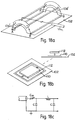
- An alternative end ring arrangement 10' is shown in Figure 4b. This provides a larger axial access.
- the end ring comprises an annulus 10' which has loop resonators 20' with slots or gaps 40'.
- the annulus has an inner surface 41 and an outer surface 42 the circular apertures 20' being formed therebetween.
- Rods 30' are joined to one end surface 43 at positions intermediate the resonators 20'.
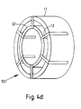
- a second series of slots 45 is formed in the second end surface 44 towards the first end surface to accommodate a flux guide or sleeve as shown in figure 4(d).
- a flux guide sleeve or end ring thimble 50 may be fitted over each end ring 10.
- a sleeve arrangement is shown in Figure 4d.
- This comprises two short coaxial conducting cylinders 11, 12, the inner cylinder 12 being held centrally within the outer cylinder by a series of conductive metallic spacers or fins 13.
- the disposition of the fins 13 is arranged to engage in the slots 45 between the slotted loop resonators of Figure 4b.
- the slots 45 must be insulated so that neither the fins 13 nor the flux guide rings 11, 12 touch the resonator 10, Figure 4b.
- a suitable insulating material could be an insulating tape or a lacquer.
- the cavity may be most easily driven from one end plate, Figure 4a, across AB or A'B' through the split capacitor arrangement, Figure 4c.
- the centre point is earthed and the coaxial drive connected to A or alternatively C. (Alternative drive and connection points are indicated with primes).
- a single capacitor of 1 ⁇ 2 Cd should be placed across the corresponding points at the other end of the cavity.
- the square of the cavity frequency, f is plotted versus 1/l in Figure 7 according to the linear regression, equation 40b.
- the slotted loop capacitance is increased by adding a segmented guard ring 21.
- actual small capacitors 22 may be inserted between the loop slots.
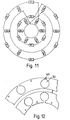
- the loop inductance may be increased by stacking machined end plates 10, 10' slightly displaced as in the schematic of Figure 10.
- successive layers of inductance must be coupled effectively in series as indicated.
- the second 10' and subsequent layers of loops must be suitably elongated.
- inductive loops so far are either flat and in the plane of the end plate or within an end ring arrangement.
- loops they may be rotated out of the plate plane by 90°, Figure 13.
- loop magnetic flux forms a toroidal shape, which is effectively contained in a torus for a large number of elements.
- the loops must be sufficiently spaced to give effectively no mutual inductance.
- flux guard plates may be introduced to separate the loops magnetically.
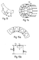
- the equivalent ⁇ circuit per section Figure 1a comprises a capacitor in series with an inductor for Z 2 and inductor for Z 1 .
- One end-plate is sketched in Figure 14. Each segment 60 is machined from solid block and the spaces 70 form a ring of series capacitors. The segments may be suitably spaced with a dielectric material.
- the above arrangement may be further modified as in Figure 15a.
- the block inductance may be increased by forming a slotted loop.
- the equivalent circuit for this arrangement is shown in Figure 15b.
- the effect of the can will be to reduce the rod inductance and also introduce a stray capacitance C s which shunts each rod.
- the shunt capacitance may be readily incorporated in the theory.
- the net effect is to increase the operating frequency f for a given cavity length.
- the magnitude of the effect depends on the proximity of the screen. For a screen/ cavity diameter ratio of 1.25 the frequency change is around 15%. This may be compensated by either increasing the resonator length or by increasing C d which lowers f 2 as outlined in the Circuit Drive description.
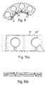
- the resonator coil designs described so far are all cage-like arrangements which completely surround the specimen around the cylindrical axis. However, there are a number of situations where it is more convenient to have a split coil system providing easy access for the specimen. Such an arrangement is desirable in the case of very small specimens and also in clinical imaging for easy access of limbs, torso, head etc.
- FIG. 16 Such a new split resonator coil arrangement is sketched in Figure 16.
- a half cavity array 100 only which is simply placed close to, but not necessarily touching, a large earthed conducting metal sheet 102.
- Two ⁇ /4 standing waves are generated about the drive point provided all four corners of the half cage are earthed.
- a magnetic field parallel to the conductor surface will be doubled and rendered uniform due to the induced image currents in the sheet.
- the arrangement will behave as though it were a single cylindrical resonator as described earlier, since the boundary conditions for an open circuit ⁇ /2 line are the same as for an open circuit or cyclic ⁇ line.
- Figure 16 is semicircular in cross-section. But in general it is possible to generate uniform transverse magnetic fields with a semi-elliptical structure in which the elliptical axes are 2a and 2b. Such an arrangement could be extremely convenient as a head coil, or as a leg or knee coil.
- the corners A,B may be joined by an inner return wire 104 providing current path continuity around the end plate. Corners P and Q should be similarly joined by a wire 106.
- pair of wires are replaced by a single strip of conductor 110, Figure 18b, and rods 2 and 3 are combined together in a flat conductive sheet 112.
- this arrangement offers a demountable coil system useful for flat samples in either microscopy or whole body imaging.
- the alternative end plate design of Figure 4b may be halved across its diameter to produce a split or half resonator design replacing the two half end plates shown in Figure 16.
- the end ring thimble Figure 4d may also be halved to fit the half resonator end rings.
- the conductive sheet 102 is preferably not a continuous sheet but may comprise a plurality of strips as indicated by dotted lines 102' in Figure 16. This is in order to satisfy the boundary conditions for RF currents but to block other induced currents at lower frequencies which would otherwise be caused by the switched gradients used in NMR.
- the strips may be formed by commencing with a continuous sheet and slitting it at appropriate distances.
- Alternative arrangements comprise cutting the sheet into suitably shaped flat loops which follow the induced RF current contours in an otherwise continuous conductive sheet.
- the passive conductive sheet is replaced by an actively driven flat wire array provided with current to simulate the induced screening currents in a flat passive conductive sheet.
- split resonator design is introduced in which half a resonator array is placed close to but not touching a flat conducting plate. Since the split coil cross-section may be semi-circular or semi-elliptical and is not fixed to the plate, the whole assembly is demountable thereby allowing easy access for limbs, head or whole body imaging.
- a variant of the split coil design is also described which corresponds to a half saddle arrangement. This may be further modified to produce a strip coil in proximity to an isolated conducting plate.
Landscapes
- Physics & Mathematics (AREA)
- Condensed Matter Physics & Semiconductors (AREA)
- General Physics & Mathematics (AREA)
- Magnetic Resonance Imaging Apparatus (AREA)
Abstract
Claims (12)
- Réseau de résonance pour résonance magnétique nucléaire RMN, destiné à être utilisé à des fréquences élevées comportant deux structures d'extrémité identiques et plusieurs tiges continues électriquement conductrices reliées électriquement aux structures d'extrémité identiques, les tiges supportant par conséquent les structures d'extrémité à une distance d'écartement prédéterminée, caractérisé en ce que les tiges (30) et les structures d'extrémité (10) comportent plusieurs tronçons de circuit électrique en π ou en T et sont formées et dimensionnées pour contribuer de manière importante aux caractéristiques électriques du réseau sous forme d'un tout et pour permettre à celui-ci de supporter une onde standard.
- Réseau de résonance pour RMN selon la revendication 1, dans lequel chaque structure d'extrémité comporte une plaque usinée (10).
- Réseau de résonance selon la revendication 2, dans lequel chaque plaque d'extrémité (10) comporte un disque sensiblement circulaire ayant des ouvertures circulaires (20) espacées de manière équidistante sur la surface du disque, dans lequel chaque ouverture est reliée à une première extrémité d'un canal allongé (40) qui s'étend jusqu'à l'intérieur d'une zone centrale commune de la plaque à laquelle l'autre extrémité de chaque canal allongé est reliée pour former une ouverture centrale, et dans lequel chaque première des plusieurs tiges continues est reliée à la plaque (10) en une position intermédiaire entre chaque canal allongé (40) pour former le réseau.
- Réseau de résonance selon la revendication 2, dans lequel les tiges sont reliées à une première plaque d'extrémité par l'intermédiaire de plusieurs trous traversants situés dans la plaque d'extrémité, chaque tige pouvant coulisser dans son trou respectif situé dans la plaque d'extrémité pour permettre par conséquent le réglage de la distance d'écartement des plaques d'extrémité.
- Réseau de résonance selon la revendication 2, dans lequel chaque plaque d'extrémité est constituée d'un anneau principal (10') ayant une surface cylindrique intérieure (41) et une surface cylindrique extérieure (42) définies par l'épaisseur de l'anneau principal et une première (43) et une seconde (44) surfaces d'extrémité définies par la largeur de l'anneau, l'anneau principal étant muni de plusieurs ouvertures circulaires (20') espacées de manière équidistante autour de sa surface, fournissant des trous circulaires traversant l'anneau principal à partir de la surface intérieure vers la surface extérieure, l'anneau principal étant aussi muni de plusieurs premières fentes (40') reliant chaque ouverture circulaire à la première surface d'extrémité et plusieurs secondes fentes (45) formées dans l'anneau principal à partir de la seconde surface d'extrémité vers la première surface d'extrémité de manière à séparer partiellement les ouvertures circulaires et une tige respective (30') des plusieurs tiges est reliée à l'anneau principal au niveau d'une première surface d'extrémité (43) au niveau d'une position respective située entre les premières fentes (40') les tiges étant espacées de manière équidistante autour de l'anneau.
- Réseau de résonance selon la revendication 5, comportant un manchon de guidage de flux (50), le manchon de guidage de flux comportant un anneau intérieur (12) et un anneau extérieur (11), l'anneau intérieur (12) ayant un diamètre plus petit que l'anneau principal et l'anneau extérieur ayant un diamètre plus grand que l'anneau principal (10'), dans lequel les anneaux intérieur (12) et extérieur (11) sont reliés ensemble par une série d'ailettes (13), dans lequel les ailettes (13) et les anneaux intérieur et extérieur sont électriquement conducteurs, et dans lequel les ailettes sont espacées selon des intervalles autour des anneaux pour coopérer avec les secondes fentes (45) pour permettre au manchon de guidage de flux d'être agencé sur chaque anneau.
- Réseau de résonance dans lequel le réseau comporte un premier et un second réseau selon la revendication 3, le premier réseau étant plus grand que le second réseau, le second réseau étant positionné à l'intérieur du premier réseau.
- Réseau de résonance selon la revendication 1, dans lequel chaque plaque d'extrémité comporte un anneau, l'anneau étant constitué de plusieurs segments électriquement conducteurs (60), chaque segment étant séparé de ses segments contigus par un isolant électrique (70) pour par conséquent isoler électriquement chaque segment, et dans lequel une tige respective (30) est reliée à chaque segment pour espacer par conséquent de manière équidistante les tiges autour de l'anneau.
- Réseau de résonance selon la revendication 1, dans lequel chaque structure d'extrémité comporte un demi-anneau, les tiges reliant par conséquent chaque demi-anneau pour former un agencement en cloche à fromage (100), et comportant une plaque électriquement conductrice (102) l'agencement en cloche à fromage étant placé sur la plaque conductrice mais ne la touchant pas.
- Réseau de résonance selon la revendication 9, dans lequel chaque demi-anneau est muni de plusieurs ouvertures circulaires le traversant et de plusieurs canaux allongés reliant chaque ouverture circulaire à une surface extérieure du demi-anneau.
- Réseau de résonance selon la revendication 1, caractérisé en ce qu'une première, une deuxième, une troisième et une quatrième tige sont agencées et chacune desdites structures d'extrémité est constituée d'un anneau partiel sur lequel lesdites deuxième et troisième tiges sont reliées, en ce que lesdites deuxième et troisième tiges sont reliées électriquement auxdites première et quatrième tiges respectivement via des condensateurs situés au niveau de chaque extrémité desdites tiges, en ce qu'une plaque électriquement conductrice est agencée à proximité desdites première (AP) et quatrième (BQ) tiges, mais n'étant pas reliée de manière conductrice avec celles-ci, et en ce que les condensateurs (104', 106') relient les extrémités de la première et de la quatrième tige directement les unes aux autres.
- Réseau de résonance selon la revendication 11, dans lequel lesdites deuxième et troisième tiges et les anneaux partiels auxquels elles sont reliées forment une première feuille continue conductrice (112) et lesdites première et quatrième tiges et les conducteurs reliant leurs extrémités forment une bande continue conductrice (110).
Applications Claiming Priority (6)
| Application Number | Priority Date | Filing Date | Title |
|---|---|---|---|
| GB8918412 | 1989-08-11 | ||
| GB898918412A GB8918412D0 (en) | 1989-08-11 | 1989-08-11 | Resonant cavities for nmr |
| GB9004593 | 1990-03-01 | ||
| GB909004593A GB9004593D0 (en) | 1990-03-01 | 1990-03-01 | Resonant cavities for nmr |
| PCT/GB1990/001259 WO1991002261A1 (fr) | 1989-08-11 | 1990-08-10 | Cavites resonnantes servant a la resonance magnetique nucleaire |
| US07/828,942 US5321360A (en) | 1989-08-11 | 1992-03-06 | Resonant cavities for NMR |
Publications (2)
| Publication Number | Publication Date |
|---|---|
| EP0486590A1 EP0486590A1 (fr) | 1992-05-27 |
| EP0486590B1 true EP0486590B1 (fr) | 1996-11-27 |
Family
ID=27264627
Family Applications (1)
| Application Number | Title | Priority Date | Filing Date |
|---|---|---|---|
| EP90912699A Expired - Lifetime EP0486590B1 (fr) | 1989-08-11 | 1990-08-10 | Cavites resonnantes servant a la resonance magnetique nucleaire |
Country Status (4)
| Country | Link |
|---|---|
| US (1) | US5321360A (fr) |
| EP (1) | EP0486590B1 (fr) |
| GB (1) | GB2235781B (fr) |
| WO (1) | WO1991002261A1 (fr) |
Families Citing this family (12)
| Publication number | Priority date | Publication date | Assignee | Title |
|---|---|---|---|---|
| JP3411631B2 (ja) * | 1993-08-30 | 2003-06-03 | 株式会社日立メディコ | Rfプローブ及び磁気共鳴イメージング装置 |
| DE4333182A1 (de) * | 1993-09-29 | 1995-03-30 | Siemens Ag | Doppeltresonante Antennenanordnung für ein Magnetresonanzgerät |
| US5502387A (en) * | 1994-08-23 | 1996-03-26 | Northrop Grumman Corporation | Variable geometry MRI coil |
| US5986454A (en) * | 1997-03-21 | 1999-11-16 | Varian, Inc. | Quadrature elliptical birdcage coil for NMR |
| KR100530432B1 (ko) * | 1997-03-21 | 2006-03-03 | 배리언 인코포레이티드 | Nmr을위한타원형직교버드케이지코일 |
| DE29716639U1 (de) * | 1997-09-16 | 1999-01-21 | Tews Elektronik, 22459 Hamburg | Mikrowellen-Streufeldsensor zur Feuchte- und/oder Dichtemessung |
| CA2334929A1 (fr) * | 2000-02-10 | 2001-08-10 | Jarod Matwiy | Bobine de champ de frequence radio en quadrature a utiliser dans la resonance magnetique |
| JP3516631B2 (ja) * | 2000-03-30 | 2004-04-05 | ジーイー・メディカル・システムズ・グローバル・テクノロジー・カンパニー・エルエルシー | Rfコイルおよび磁気共鳴撮影装置 |
| AU2001263072A1 (en) * | 2000-05-11 | 2001-11-20 | Uab Research Foundation | High frequency large volume resonator |
| US6781378B2 (en) * | 2002-02-19 | 2004-08-24 | Siemens Aktiengesellschaft | Radio-frequency antenna for a magnetic resonance system |
| US7106063B1 (en) * | 2005-08-05 | 2006-09-12 | Varian, Inc. | Axially constrained RF probe coil |
| EP2203757A2 (fr) * | 2007-10-17 | 2010-07-07 | Koninklijke Philips Electronics N.V. | Bobine en cage à oiseaux présentant une homogénéité améliorée et un sar réduit |
Family Cites Families (8)
| Publication number | Priority date | Publication date | Assignee | Title |
|---|---|---|---|---|
| GB8334374D0 (en) * | 1983-12-23 | 1984-02-01 | Picker Int Ltd | Coil arrangements |
| GB8405066D0 (en) * | 1984-02-27 | 1984-04-04 | Picker Int Ltd | Coil arrangements |
| FR2567647B1 (fr) * | 1984-07-10 | 1987-12-18 | Thomson Cgr | Dispositif de creation et/ou de reception d'un champ magnetique alternatif pour appareil exploitant la resonance magnetique nucleaire |
| DE3522401A1 (de) * | 1985-06-22 | 1987-01-02 | Bruker Medizintech | Probenkopf fuer die nmr-tomographie |
| NL8502273A (nl) * | 1985-08-19 | 1987-03-16 | Philips Nv | Magnetisch resonantie apparaat met bird cage r.f. spoel. |
| NL8603251A (nl) * | 1986-12-22 | 1988-07-18 | Philips Nv | Magnetisch resonantie-apparaat met inschakelbare bird-cage r.f.-spoel. |
| US4825163A (en) * | 1987-07-31 | 1989-04-25 | Hitachi, Ltd. | Quadrature probe for nuclear magnetic resonance |
| US4845431A (en) * | 1988-03-18 | 1989-07-04 | University Of Pittsburgh | Variable aperture, variable frequency extremity coil for magnetic resonance imaging |
-
1990
- 1990-08-10 EP EP90912699A patent/EP0486590B1/fr not_active Expired - Lifetime
- 1990-08-10 WO PCT/GB1990/001259 patent/WO1991002261A1/fr not_active Ceased
- 1990-08-10 GB GB9017596A patent/GB2235781B/en not_active Expired - Fee Related
-
1992
- 1992-03-06 US US07/828,942 patent/US5321360A/en not_active Expired - Lifetime
Also Published As
| Publication number | Publication date |
|---|---|
| GB2235781A (en) | 1991-03-13 |
| GB9017596D0 (en) | 1990-09-26 |
| WO1991002261A1 (fr) | 1991-02-21 |
| US5321360A (en) | 1994-06-14 |
| GB2235781B (en) | 1994-05-04 |
| EP0486590A1 (fr) | 1992-05-27 |
Similar Documents
| Publication | Publication Date | Title |
|---|---|---|
| KR880001528B1 (ko) | 핵자기 공명용 rf코일 | |
| US4751464A (en) | Cavity resonator with improved magnetic field uniformity for high frequency operation and reduced dielectric heating in NMR imaging devices | |
| US6060882A (en) | Low-inductance transverse litz foil coils | |
| US8779768B2 (en) | NMR RF probe coil exhibiting double resonance | |
| US4694255A (en) | Radio frequency field coil for NMR | |
| US5143688A (en) | Surface electrical coil structures | |
| EP0180121B1 (fr) | Dispositif pour adapter une bobine de RMN à l'aide de l'induction mutuelle | |
| US4887039A (en) | Method for providing multiple coaxial cable connections to a radio-frequency antenna without baluns | |
| US4446429A (en) | Microwave resonator | |
| US4594566A (en) | High frequency rf coil for NMR device | |
| US6121776A (en) | Superconducting hybrid-resonator for receiving NMR-signals | |
| EP0486590B1 (fr) | Cavites resonnantes servant a la resonance magnetique nucleaire | |
| EP0160942A2 (fr) | Résonateur pour le domaine des radio fréquences en forme de tube fendu à section elliptique pour l'imagerie par résonance magnétique nucléaire | |
| JP2002328156A (ja) | 局部磁場発生素子及びコンデンサ素子を備えるnmr平面コイル | |
| US6175237B1 (en) | Center-fed paralleled coils for MRI | |
| Mansfield et al. | High frequency cavity resonator designs for NMR | |
| CA2064763C (fr) | Cavites resonnantes pour rmn | |
| US20130328564A1 (en) | Nmr rf probe coil exhibiting double resonance | |
| EP3655790B1 (fr) | Bobine rmn accordable et tête de sonde contenant une telle bobine | |
| JPH0424019A (ja) | 磁気共鳴装置用高周波プローブ | |
| WO1997033185A1 (fr) | Bobines paralleles a alimentation centrale pour imagerie rmn |
Legal Events
| Date | Code | Title | Description |
|---|---|---|---|
| PUAI | Public reference made under article 153(3) epc to a published international application that has entered the european phase |
Free format text: ORIGINAL CODE: 0009012 |
|
| 17P | Request for examination filed |
Effective date: 19920124 |
|
| AK | Designated contracting states |
Kind code of ref document: A1 Designated state(s): CH DE FR IT LI NL |
|
| RAP1 | Party data changed (applicant data changed or rights of an application transferred) |
Owner name: BRITISH TECHNOLOGY GROUP LTD |
|
| 17Q | First examination report despatched |
Effective date: 19950707 |
|
| GRAG | Despatch of communication of intention to grant |
Free format text: ORIGINAL CODE: EPIDOS AGRA |
|
| GRAH | Despatch of communication of intention to grant a patent |
Free format text: ORIGINAL CODE: EPIDOS IGRA |
|
| GRAH | Despatch of communication of intention to grant a patent |
Free format text: ORIGINAL CODE: EPIDOS IGRA |
|
| GRAA | (expected) grant |
Free format text: ORIGINAL CODE: 0009210 |
|
| AK | Designated contracting states |
Kind code of ref document: B1 Designated state(s): CH DE FR IT LI NL |
|
| PG25 | Lapsed in a contracting state [announced via postgrant information from national office to epo] |
Ref country code: CH Effective date: 19961127 Ref country code: LI Effective date: 19961127 |
|
| ITF | It: translation for a ep patent filed | ||
| REF | Corresponds to: |
Ref document number: 69029267 Country of ref document: DE Date of ref document: 19970109 |
|
| ET | Fr: translation filed | ||
| REG | Reference to a national code |
Ref country code: CH Ref legal event code: PL |
|
| PLBE | No opposition filed within time limit |
Free format text: ORIGINAL CODE: 0009261 |
|
| STAA | Information on the status of an ep patent application or granted ep patent |
Free format text: STATUS: NO OPPOSITION FILED WITHIN TIME LIMIT |
|
| 26N | No opposition filed | ||
| PGFP | Annual fee paid to national office [announced via postgrant information from national office to epo] |
Ref country code: DE Payment date: 20070802 Year of fee payment: 18 |
|
| PGFP | Annual fee paid to national office [announced via postgrant information from national office to epo] |
Ref country code: IT Payment date: 20070828 Year of fee payment: 18 Ref country code: NL Payment date: 20070805 Year of fee payment: 18 |
|
| PGFP | Annual fee paid to national office [announced via postgrant information from national office to epo] |
Ref country code: FR Payment date: 20070808 Year of fee payment: 18 |
|
| NLV4 | Nl: lapsed or anulled due to non-payment of the annual fee |
Effective date: 20090301 |
|
| PG25 | Lapsed in a contracting state [announced via postgrant information from national office to epo] |
Ref country code: NL Free format text: LAPSE BECAUSE OF NON-PAYMENT OF DUE FEES Effective date: 20090301 |
|
| REG | Reference to a national code |
Ref country code: FR Ref legal event code: ST Effective date: 20090430 |
|
| PG25 | Lapsed in a contracting state [announced via postgrant information from national office to epo] |
Ref country code: IT Free format text: LAPSE BECAUSE OF NON-PAYMENT OF DUE FEES Effective date: 20080810 Ref country code: DE Free format text: LAPSE BECAUSE OF NON-PAYMENT OF DUE FEES Effective date: 20090303 Ref country code: FR Free format text: LAPSE BECAUSE OF NON-PAYMENT OF DUE FEES Effective date: 20080901 |