EP0486662B1 - Einrichtung und verfahren zur direkten papierzuführung für druckvorrichtungen - Google Patents
Einrichtung und verfahren zur direkten papierzuführung für druckvorrichtungen Download PDFInfo
- Publication number
- EP0486662B1 EP0486662B1 EP91911410A EP91911410A EP0486662B1 EP 0486662 B1 EP0486662 B1 EP 0486662B1 EP 91911410 A EP91911410 A EP 91911410A EP 91911410 A EP91911410 A EP 91911410A EP 0486662 B1 EP0486662 B1 EP 0486662B1
- Authority
- EP
- European Patent Office
- Prior art keywords
- sheet
- sheets
- support structure
- set forth
- input port
- Prior art date
- Legal status (The legal status is an assumption and is not a legal conclusion. Google has not performed a legal analysis and makes no representation as to the accuracy of the status listed.)
- Expired - Lifetime
Links
Images

Classifications
-
- B—PERFORMING OPERATIONS; TRANSPORTING
- B65—CONVEYING; PACKING; STORING; HANDLING THIN OR FILAMENTARY MATERIAL
- B65H—HANDLING THIN OR FILAMENTARY MATERIAL, e.g. SHEETS, WEBS, CABLES
- B65H9/00—Registering, e.g. orientating, articles; Devices therefor
- B65H9/16—Inclined tape, roller, or like article-forwarding side registers
- B65H9/163—Tape
-
- B—PERFORMING OPERATIONS; TRANSPORTING
- B65—CONVEYING; PACKING; STORING; HANDLING THIN OR FILAMENTARY MATERIAL
- B65H—HANDLING THIN OR FILAMENTARY MATERIAL, e.g. SHEETS, WEBS, CABLES
- B65H35/00—Delivering articles from cutting or line-perforating machines; Article or web delivery apparatus incorporating cutting or line-perforating devices, e.g. adhesive tape dispensers
- B65H35/0006—Article or web delivery apparatus incorporating cutting or line-perforating devices
-
- B—PERFORMING OPERATIONS; TRANSPORTING
- B65—CONVEYING; PACKING; STORING; HANDLING THIN OR FILAMENTARY MATERIAL
- B65H—HANDLING THIN OR FILAMENTARY MATERIAL, e.g. SHEETS, WEBS, CABLES
- B65H43/00—Use of control, checking, or safety devices, e.g. automatic devices comprising an element for sensing a variable
-
- B—PERFORMING OPERATIONS; TRANSPORTING
- B65—CONVEYING; PACKING; STORING; HANDLING THIN OR FILAMENTARY MATERIAL
- B65H—HANDLING THIN OR FILAMENTARY MATERIAL, e.g. SHEETS, WEBS, CABLES
- B65H5/00—Feeding articles separated from piles; Feeding articles to machines
- B65H5/02—Feeding articles separated from piles; Feeding articles to machines by belts or chains, e.g. between belts or chains
- B65H5/021—Feeding articles separated from piles; Feeding articles to machines by belts or chains, e.g. between belts or chains by belts
- B65H5/025—Feeding articles separated from piles; Feeding articles to machines by belts or chains, e.g. between belts or chains by belts between belts and rotary means, e.g. rollers, drums, cylinders or balls, forming a transport nip
-
- B—PERFORMING OPERATIONS; TRANSPORTING
- B65—CONVEYING; PACKING; STORING; HANDLING THIN OR FILAMENTARY MATERIAL
- B65H—HANDLING THIN OR FILAMENTARY MATERIAL, e.g. SHEETS, WEBS, CABLES
- B65H5/00—Feeding articles separated from piles; Feeding articles to machines
- B65H5/06—Feeding articles separated from piles; Feeding articles to machines by rollers or balls, e.g. between rollers
- B65H5/066—Feeding articles separated from piles; Feeding articles to machines by rollers or balls, e.g. between rollers the articles resting on rollers or balls
-
- B—PERFORMING OPERATIONS; TRANSPORTING
- B65—CONVEYING; PACKING; STORING; HANDLING THIN OR FILAMENTARY MATERIAL
- B65H—HANDLING THIN OR FILAMENTARY MATERIAL, e.g. SHEETS, WEBS, CABLES
- B65H5/00—Feeding articles separated from piles; Feeding articles to machines
- B65H5/34—Varying the phase of feed relative to the receiving machine
-
- G—PHYSICS
- G03—PHOTOGRAPHY; CINEMATOGRAPHY; ANALOGOUS TECHNIQUES USING WAVES OTHER THAN OPTICAL WAVES; ELECTROGRAPHY; HOLOGRAPHY
- G03G—ELECTROGRAPHY; ELECTROPHOTOGRAPHY; MAGNETOGRAPHY
- G03G15/00—Apparatus for electrographic processes using a charge pattern
- G03G15/65—Apparatus which relate to the handling of copy material
- G03G15/6517—Apparatus for continuous web copy material of plain paper, e.g. supply rolls; Roll holders therefor
-
- G—PHYSICS
- G03—PHOTOGRAPHY; CINEMATOGRAPHY; ANALOGOUS TECHNIQUES USING WAVES OTHER THAN OPTICAL WAVES; ELECTROGRAPHY; HOLOGRAPHY
- G03G—ELECTROGRAPHY; ELECTROPHOTOGRAPHY; MAGNETOGRAPHY
- G03G15/00—Apparatus for electrographic processes using a charge pattern
- G03G15/65—Apparatus which relate to the handling of copy material
- G03G15/6517—Apparatus for continuous web copy material of plain paper, e.g. supply rolls; Roll holders therefor
- G03G15/6523—Cutting
-
- G—PHYSICS
- G03—PHOTOGRAPHY; CINEMATOGRAPHY; ANALOGOUS TECHNIQUES USING WAVES OTHER THAN OPTICAL WAVES; ELECTROGRAPHY; HOLOGRAPHY
- G03G—ELECTROGRAPHY; ELECTROPHOTOGRAPHY; MAGNETOGRAPHY
- G03G15/00—Apparatus for electrographic processes using a charge pattern
- G03G15/65—Apparatus which relate to the handling of copy material
- G03G15/6555—Handling of sheet copy material taking place in a specific part of the copy material feeding path
- G03G15/6558—Feeding path after the copy sheet preparation and up to the transfer point, e.g. registering; Deskewing; Correct timing of sheet feeding to the transfer point
- G03G15/6561—Feeding path after the copy sheet preparation and up to the transfer point, e.g. registering; Deskewing; Correct timing of sheet feeding to the transfer point for sheet registration
- G03G15/6564—Feeding path after the copy sheet preparation and up to the transfer point, e.g. registering; Deskewing; Correct timing of sheet feeding to the transfer point for sheet registration with correct timing of sheet feeding
-
- B—PERFORMING OPERATIONS; TRANSPORTING
- B65—CONVEYING; PACKING; STORING; HANDLING THIN OR FILAMENTARY MATERIAL
- B65H—HANDLING THIN OR FILAMENTARY MATERIAL, e.g. SHEETS, WEBS, CABLES
- B65H2301/00—Handling processes for sheets or webs
- B65H2301/10—Selective handling processes
- B65H2301/12—Selective handling processes of sheets or web
- B65H2301/121—Selective handling processes of sheets or web for sheet handling processes, i.e. wherein the web is cut into sheets
-
- B—PERFORMING OPERATIONS; TRANSPORTING
- B65—CONVEYING; PACKING; STORING; HANDLING THIN OR FILAMENTARY MATERIAL
- B65H—HANDLING THIN OR FILAMENTARY MATERIAL, e.g. SHEETS, WEBS, CABLES
- B65H2301/00—Handling processes for sheets or webs
- B65H2301/30—Orientation, displacement, position of the handled material
- B65H2301/33—Modifying, selecting, changing orientation
-
- B—PERFORMING OPERATIONS; TRANSPORTING
- B65—CONVEYING; PACKING; STORING; HANDLING THIN OR FILAMENTARY MATERIAL
- B65H—HANDLING THIN OR FILAMENTARY MATERIAL, e.g. SHEETS, WEBS, CABLES
- B65H2301/00—Handling processes for sheets or webs
- B65H2301/30—Orientation, displacement, position of the handled material
- B65H2301/34—Modifying, selecting, changing direction of displacement
-
- B—PERFORMING OPERATIONS; TRANSPORTING
- B65—CONVEYING; PACKING; STORING; HANDLING THIN OR FILAMENTARY MATERIAL
- B65H—HANDLING THIN OR FILAMENTARY MATERIAL, e.g. SHEETS, WEBS, CABLES
- B65H2301/00—Handling processes for sheets or webs
- B65H2301/30—Orientation, displacement, position of the handled material
- B65H2301/36—Positioning; Changing position
-
- B—PERFORMING OPERATIONS; TRANSPORTING
- B65—CONVEYING; PACKING; STORING; HANDLING THIN OR FILAMENTARY MATERIAL
- B65H—HANDLING THIN OR FILAMENTARY MATERIAL, e.g. SHEETS, WEBS, CABLES
- B65H2511/00—Dimensions; Position; Numbers; Identification; Occurrences
- B65H2511/20—Location in space
-
- B—PERFORMING OPERATIONS; TRANSPORTING
- B65—CONVEYING; PACKING; STORING; HANDLING THIN OR FILAMENTARY MATERIAL
- B65H—HANDLING THIN OR FILAMENTARY MATERIAL, e.g. SHEETS, WEBS, CABLES
- B65H2511/00—Dimensions; Position; Numbers; Identification; Occurrences
- B65H2511/50—Occurence
- B65H2511/51—Presence
-
- B—PERFORMING OPERATIONS; TRANSPORTING
- B65—CONVEYING; PACKING; STORING; HANDLING THIN OR FILAMENTARY MATERIAL
- B65H—HANDLING THIN OR FILAMENTARY MATERIAL, e.g. SHEETS, WEBS, CABLES
- B65H2513/00—Dynamic entities; Timing aspects
- B65H2513/50—Timing
- B65H2513/51—Sequence of process
-
- B—PERFORMING OPERATIONS; TRANSPORTING
- B65—CONVEYING; PACKING; STORING; HANDLING THIN OR FILAMENTARY MATERIAL
- B65H—HANDLING THIN OR FILAMENTARY MATERIAL, e.g. SHEETS, WEBS, CABLES
- B65H2701/00—Handled material; Storage means
- B65H2701/10—Handled articles or webs
- B65H2701/13—Parts concerned of the handled material
- B65H2701/131—Edges
- B65H2701/1311—Edges leading edge
-
- Y—GENERAL TAGGING OF NEW TECHNOLOGICAL DEVELOPMENTS; GENERAL TAGGING OF CROSS-SECTIONAL TECHNOLOGIES SPANNING OVER SEVERAL SECTIONS OF THE IPC; TECHNICAL SUBJECTS COVERED BY FORMER USPC CROSS-REFERENCE ART COLLECTIONS [XRACs] AND DIGESTS
- Y10—TECHNICAL SUBJECTS COVERED BY FORMER USPC
- Y10T—TECHNICAL SUBJECTS COVERED BY FORMER US CLASSIFICATION
- Y10T83/00—Cutting
- Y10T83/505—Operation controlled by means responsive to product
- Y10T83/515—Actuation of tool controlled
Definitions
- This invention relates to an apparatus and a method for feeding a continuous stream of paper to a printing device without any need for stacking and deshingling individual sheets of paper.
- Previous devices by for instance, Hunkler of Switzerland, have dealt with the problem of providing a continuous roll source of paper to a printer, designed only for use with stacked paper sheets, by continuously cutting and adding additional sheets from the roll to this input paper stack feed unit.
- This method has been particularly adapted for the XeroxTM 87xx and 97xx series such as the 9700 Laser Printer, and for various duplicators.
- the problem with this method is that the printer must still deshingle and individually feed sheets of paper from the stack feed unit. The result is increased, rather than decreased overall complexity and a greater chance of system failure due to the need to now accurately cut and stack paper sheets from the roll as well as to subsequently unstack the sheets of paper to feed them to the printer.
- This unique invention provides a system and method for directly feeding unstacked paper sheets into a printing device having movage image conducting element with a plurality of images for transfer to the paper placed thereon and also having a wait station for controlling the timing of paper transfer to the image conducting element.
- the system comprises a means for directing a continuous stream of paper sheets to a printing device wait station.
- Means are provided for regulating the spacing of a leading edge of each paper sheet as it is presented to the wait station. This spacing is relative to the spacing between consecutive images on the image conducting element.
- the printing device is a laser printer and the image conducting element is one of either a constant speed belt or drum, upon which, images are placed for transfer.
- This system may be particularly adapted to a XeroxTM 9700 series laser printer.
- There may be provided a means for controlling the rate of paper sheet feeding that includes a predetermined rate equal to approximately 50,8 cm (20 inches) per second and a means for regulating the spacing of fed paper sheets that includes a spacing equal to approximately 25,4 cm (10 inches).
- the system may also comprise a means for cutting the paper sheets to predetermined sizes from the input of a continuous paper web. This continuous paper web may be input from a roll.
- the means for regulating paper spacing may include a means for detecting the leading edge of each paper sheet.
- a system for directly feeding sheets to a printing device provides a means for bypassing a printer stack feeding storage unit that includes a table for guiding sheets in a downstream direction into the stack deshingler.
- the stack deshingler itself is a unit that removes sheets one at a time and positions the sheets within a wait station means which, itself, feeds these sheets to an image transfer element upon demand of the image transfer element.
- the table includes a means for detecting movement of each sheet upon the table through the stack deshingler and into the image transfer element and/wait station. There is additionally provided on the table a means for sensing the absence of a sheet proximate the stack deshingler.
- the table further includes a means for driving sheets therealong from an upstream side to the stack deshingler in response to the absence of a sheet at the means for sensing.
- Sheets are provided at the upstream side of the table to the means for driving in response to at least one or both of the means for sensing absence of sheets and means for detecting movements of sheets.
- the sheets provided to the upstream side of the table may originate from a roll source of continuous web that is cut on demand in response to the detection of movement of sheets through the deshingler. Sheets are continuously driven into the cutter to lay partially upon the table in response to the sensing of the absence of sheets as they are fed to the image transfer element.
- the roll source, the cutter feeder, and particularly the table may include wheels to allow their motion to and from the printer.
- Each of these units is modular and may be operated without any specific electronic interconnection with the printer.
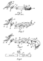
- FIG. 1 A photoreprographic printing system of the prior art is generally depicted in FIG. 1.
- This type of printing system is used, for example, in the Xerox" 9700 Series Laser Printer. It generally consists of an image conductor element 22 comprising either a belt or drum upon which printing toner is placed in the form of the desired print images.
- the image conductor belt 22 shown herein contains several images 28 that are laid down at 24 upon a piece of paper 26 as it passes under the contacting surface of the belt. Each piece of paper is fed to the image element by means of a "wait station" 30.
- This wait station includes a pair of rollers that forcibly drive a sheet of paper into the image element at a given time corresponding to the motion of the image conductor belt.
- the wait station 30 is synchronized to drive the leading edge 31 of a sheet of paper 32 into the image conductor belt each time an image on the image conductor belt 22 is aligned to properly print upon the sheet of paper when it reaches the image conductor belt.
- the feeding of the wait station is accomplished in most printer systems by deshingling a stack of paper 46, one sheet at a time, and feeding each sheet 44 at a predetermined rate to the wait station 30, using a feed driving belt and pinching roller 40 and 42, respectively. As each sheet is fed to the wait station it is held for a small interval until the image element is again ready to receive a new piece. If the wait station does not receive a new piece of paper by the time the next image is ready to be printed, the system will shut down displaying a jam or paper refill signal.
- Any feeding system that correctly interfaces with this type of printer must be able to directly feed the wait station of the printing element so that it receives a sheet of paper within the correct period of time to prevent the wait station from indicating an error. Also, it must not feed too quickly since this would cause a feeding backlog at the wait station.
- paper sheets 70 are fed to a conveying or feeding station 60 that moves paper at a specific rate R to the wait station 30.
- Each sheet is delivered to the station 30 at a specific point of time in order to insure that it be fed to the image conducting belt 22 in synchronization with the print images laid down on the belt.
- the parameters of image conducting belt speed S and the distance between the leading edge of each new image d on the image conducting belt is determined. These parameters are directly relative to the feeding speed.
- the image belt speed is 50,8 cm (20 inches) per second and the distance between each image leading edge D is 25,4 cm (10 inches).
- the system 60 is designed to separate each leading edge of input paper sheets by a distance D that equals the image conducting belt image distance d. In this case, the distance is 10 inches.
- each paper sheet 61 are separated by the distance D. This spacing may be accomplished by detecting at 72 the leading edge of a sheet each time a sheet is presented to a feeding mechanism or conveyor 60. Each sheet is motioned down the feeding mechanism 60 when the appropriate distance from the preceding leading edge has been attained. Furthermore, each sheet of paper driven at this distance D travels down the feeding mechanism at a fixed rate R. In this example, the rate R will equal 50,4 cm (20 inches) per second, or the rate of the image conducting belt.
- the rate R will equal 50,4 cm (20 inches) per second, or the rate of the image conducting belt.
- the second sheet 61 and third sheet 63 are of different sizes while each sheet's leading edge is aligned at precisely the same distance from the preceding one.
- This novel system only allows the next sheet to begin motion when the preceding leading edge has traveled exactly a distance D from the next sheet's leading edge. Since printing may occur without regard to size, the printing of unfolded envelopes, among other applications, is possible in large unstacked volume.
- a significant feature of the direct feeding concept is the ability to input a continuous web of paper to the printing system.
- a roll 89 of paper web 91 is shown in FIG. 3.
- This paper web 91 is fed in a continuous manner into a cutting unit 95.
- the cutting unit 95 cuts sheets to a programmed or otherwise predetermined size sheet 81 that are then driven down the feeding device 79 with the required spacing D.
- the sheets are then delivered by the feeding mechanism or conveyor 79 to the wait station 30 and printed upon in the manner described herein above.
- the feed rate of the roll 93 to the cutting device 95 is synchronized to the general feed rate of the feeding mechanism 79. If so, each time a sheet is cut it may proceed on to the feeding device without delay.
- the station 30 may operate continuously assuming that the spacing D is proper as introduced to the station 30.
- the station 30 may operate somewhat intermittently with a slight wait possible for proper synchronization. Sheets can be provided early to the station 30 but cannot be provided late as this would cause a malfunction and shut-down.
- each sheet of paper is carried by the feeding mechanism or conveyor 60 once the appropriate distance from the preceding leading edge has been attained.
- the feeding mechanism 60 is set up for operation at a programmed or otherwise predetermined speed to match that of the image conducting belt 22, then one can employ a leading edge detector to determine the presence of a leading edge of a sheet being fed to the feeding device 60. Once this leading edge is detected, the input feed to the feeding mechanism 60 can be interrupted until the proper spacing occurs, namely the spacing D in FIG. 2 at which time the input feed proceeds so that all leading edges are spaced the proper programmed distance, namely distance D in FIG. 2.
- feeding mechanisms there can be separate feeding mechanisms, including an origination feeding mechanism and a feeding mechanism such as the conveyor-like feeding mechanism 60 shown in FIG. 2.
- the leading edge detector would, in essence, be between these two feeding mechanisms and would in essence take input sheets fed in a serial course that might be unsynchronized positionally and essentially convert the sheets into a synchronized positional arrangement on the feeding mechanism 60. Again, this occurs by detecting leading edges on the input feed mechanism and then permitting the sheets to be fed to the feeding mechanism 60 but only once the proper spacing D has been achieved.
- FIG. 4 is a schematic diagram illustrating the conveyor 60 as well as an input feed 74, and edge detector 72, and a typical sheet 73.
- the sheet 73 is fed on the input feed.
- the edge detector 72 detects an edge of this sheet and essentially holds the sheet in readiness for the conveyor 60 moving to a particular position at which time the sheet 73 continues to be fed onto the conveyor 60 with the proper spacing between sheets as illustrated in FIG. 2 by the spacing D.
- FIG. 5 An alternative embodiment of a sheet feeding system according to this invention is depicted somewhat schematically in FIG. 5.
- the system includes a printer 80 such as the XeroxTM 9700 Laser Printer having an image element 82 that revolves to place toner in the form of text 84 upon sheets 86 passed thereunder.
- the image element 82 rotates continuously and when the text 84 on the element 82 is circumferentially positioned in alignment with a leading edge of a sheet, the sheet is then advanced through the image element by means of the "wait station" 88.
- the wait station 88 in this example is a pair of pinch rollers 90 that hold the sheet 86 until the proper synchronization of image element text to sheet position is obtained.
- the sheet 86 is then advanced downstream by the wait station rollers 90 along a printer feeding table 92 so that it converges with the text-carrying portion of the image element at the proper time. In this way, text is accurately laid upon the appropriate section of the sheet.
- the wait station 88 is then free to receive another sheet which it will hold until the image element again rotates to place the text in a proper position in which to begin driving the next sheet into convergence with the image element 82.
- sheets are deshingled from a stack which, in this embodiment, is supported on an upwardly moving base 94 that is built into the printer 80.
- the deshingler itself comprises elastomeric wheel 96 that projects over an edge of the printer feeding table.
- sheets would be driven upwardly by the base 94 to the level of the printer feeding table 92, as sheets were removed by the deshingler wheel 96, so that a top sheet in the stack would remain in contact with the deshingler wheel 96.
- the deshingler wheel 96 would be commanded to rotate to drive the sheet into the wait station 88 sometime soon after a prior sheet had moved downstream, clearing the wait station 88, and had been driven through the image element 82.
- the wait station 88 would always have a reserve deshingled sheet to present to the image element 82 at the appropriate time.
- a printer that utilizes only stack feeding must be refilled quite frequently. It would be desirable, instead, to continuously and directly feed sheets to the wait station from a much larger source than an integral stack feeder.
- a source derived from a roll 98 of continuous web is utilized. Such a source may contain many times the number of sheets as a typical printer storage stack.
- a modular system is utilized for feeding sheets from the roll source 98 according to this embodiment.
- Each separate unit of the system may, thus, be attached to and detached from the printer 80 and each other without substantial alteration of the printer's working components or operating software.
- Rollers or wheels 99 are provided for portability.
- a modular sheet feeder 100 according to this invention, having wheels for portability, is mounted into the preexisting stack feed access port 102 of the printer 80.
- the sheet feeder 100 is constructed with a table 104 that aligns with and is level with the printer feeding table 92 and has a downstream edge 106 that stands directly below the deshingler wheel 96. Thus sheets may pass unimpeded from the sheet feeder's table 104 to the printer feeding table 92.
- the sheet feeder 100 may include guiding lugs 108 or similar locking elements that help to maintain the sheet feeder module 100 in alignment with the printer 80.
- the printer 80 has been modified to include an extended drive belt 110 and idler roller 112 that are rotatably connected to the deshingler wheel and that further overlap the table 104 of the feeder 100.
- the feeder's table 104 is elevated in the region of the stack base 94 so that it effectively bypasses (bridges) the stack base 94 and enables the transfer of a horizontal stream of sheets one at a time directly to the deshingler assembly 96, 110, 112 and wait station 88 units from outside the normal bounds of the printer housing.
- the primary substantive alteration to the normal printer functioning in this embodiment is the extending of the deshingler wheel 96 which may be accomplished by a simple attachable and detachable component that includes the belt 110 and idler roller 112.
- the sheet feeder 100 itself includes movable side edge guides 114 to maintain sheets in appropriate transverse alignment as they are fed. It further includes, in this embodiment, a pair of spring loaded strips 116 to lightly maintain the sheets flatly against the table 104.
- Operation of the sheet feeder 100 is accomplished by means of a drive or conveyor belt 118 disposed somewhat pressurably, opposite the surface of the table 104 to contact and transfer sheets (120) on demand from a sheet feeder upstream or input side 122 to the deshingler.
- the belt 118 may be slightly angled relative to the feeding direction to force sheets accurately up against an edge guide 114.
- the accurate driving of the belt 118 to transfer sheets downstream may be accomplished using, for example, a stepper or servo motor or a ratchet clutch. This process will be described further below.
- Sheets are formed at the upstream input edge 122 of the feeder 100 by means of a cutter feeder apparatus 124 that draws a continuous web 126 from the roll feed/unwind unit 128.
- the roll feed/unwind unit 128 itself provides web upon demand of the cutter/feeder by means of a constant size loop 130 of web.
- This loop 130 is maintained at a constant size by means of a loop detector 132 that signals driving of the roll feed unit 128 as it becomes smaller due to cutter/feeder 124 drawing of web 126.
- One such roll feed unit for providing web upon demand is Applicant's Roll Support and Feed Apparatus, U.S. Patent Number 4,893,763.
- Continuous web 126 is drawn from the roll feed unit loop 130 specifically by means of a pair of driving rollers 134 or similar conveyors (such as pin feed conveyors) that bias the leading edge 136 of the web 126 downstream through a cutter 138.
- the precise distance of biasing depends upon the size of sheet selected.
- the cutter/feeder 124 meters out a length of web equal to the programmed sheet length. The trailing (upstream) edge of this metered length finds itself under the blade 140 of the cutter 138 while the leading edge 136 is disposed upon the table 104 the sheet feeder 100.
- the modular and independent functioning of the system is based upon the controlling of each of the sheet feeder 100 and cutter/feeder 124 independently of the printer 80 using a separate control logic circuit 142 that interconnects each of the systems operating elements. Control is based primarily upon at least one table 104 mounted detector 144 that senses the state of a sheet relative to the image element 82 and wait station 88 in order to instruct the system. Note that the sensing occurs without directly tapping into printer operating functions. The functioning of the system based upon the control logic circuit 142 is described further in FIGS. 6-9.
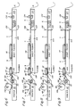
- FIGS. 6-9 The operation of the system according to FIGS. 6-9 is depicted at various states. These figures illustrate the process in an on-going manner in which the initialization of feeding has already occurred. Arrows show the operation of various elements and the timing of such operation.
- FIG. 6 shows a sheet A being driven in a downstream direction by the rollers 90 of the wait station 88 into contact with the image element 82.
- the image element 82 contains text 84 along its circumference between two points 146, 148.
- the image element 82 moves at a constant rate throughout the feeding process without stopping as long as it is instructed to continue printing.
- the trailing (upstream) edge of the sheet A passes under the deshingler roller and the attached belt and idler roller.
- the deshingler roller usually includes a one-way clutch so that when the wait station rollers begin their rapid driving of the sheet, no resistive drag is imparted by the generally slower moving deshingler roller.
- a second sheet B is positioned upstream of sheet A in a stationary position at the sheet feeder drive belt 118. This sheet is awaiting complete feeding of sheet A into the image element 82.
- a sheet C is also positioned on the sheet feeder table 104 near the input side 122 thereof. This sheet (C) is stationary, resting partially within the cutter/feeder 124 and partially within the sheet feeder. It is in the process of being cut from a continuous web D and E which extends upstream of the cutter/feeder 124. The rest of the input web D and E is likewise, stationary while the sheet A is being transferred into the image element 82 by the wait station 88.
- a detector 144 which in this example is positioned proximate the downstream end 106 of the sheet feeder table 104 detects movement of sheet A into the image element 82. As a result of the presence of a moving sheet, the detector signals a "GOING" condition to the control logic 142 of FIG. 5. The control logic 142, thus, signals the cutter 138 to immediately separate input sheet C from the remainder of the continuous web D and E. Sheet C is, thus, fully separated from the web and ready to be pulled by the upstream end of the drive belt 118 at the appropriate time.
- each of the upstream disposed sheets following the transfer of sheet A is accomplished as shown in FIG. 7.
- the detector 144 of this embodiment senses the absence of a sheet. This absence is translated into a "GONE" signal to the control logic 142.
- the control logic 142 in response to a "GONE", signals the cutter/feeder 124 and the sheet feeder drive belt 118 to translate over a distance sufficient to transfer sheet B into the deshingler belt assembly 96, 110, 112 and simultaneously transfer sheet C to the position formerly occupied by sheet B, just upstream of the deshingler assembly.
- the rollers 134 of the cutter/feeder 124 feed the leading (downstream) edge of the continuous web D and E onto the sheet feeder.
- FIG. 8 The completed repositioning (shown in progress in FIG. 7) of sheets is depicted in FIG. 8.
- Sheet B is now positioned within the wait station rollers 90 with its leading edge slightly (approximately 2,54 cm (one inch) thereof) protruding downstream while sheet C stands in the belt 118, ready to be fed to the deshingler assembly 96, 110, 112 and sheet D now stands with its downstream leading edge partially under the feeder drive belt and its uncut upstream trailing edge located proximate the cutter. At this time, sheet D is still part of the continuous web E within the cutter/feeder. Note that while all other elements are stationary, the image element continues to rotate with the circumferential text image 84 not yet in synchronization with the next sheet B. The printer will again signal driving of the wait station rollers 90 only when the image 84 has rotated to the proper position to effect synchronized convergence of a driven sheet B with the image 84. Since sheet A has been completed, it is shown exiting the printer feeding table 92.
- each module of the system of this invention remains stationary awaiting proper alignment of the image element 82.
- the wait station rollers 90 hold sheet B in a stationary unfed position.
- the wait station rollers 90 are dependent for their movement directly upon the positioning of the image element 82 and are an integral part of the printer mechanism.
- the detector 144 senses the presence of a non-moving sheet therein.
- the detector consequently, signals a neutral or "WAIT" state in which the logic control 142 (FIG. 5) directs each of the sheet feeder belt 118 and cutter/feeder unit 124 to neither advance nor cut sheets.
- the printer then signals the wait station rollers 90 to begin driving sheet B as depicted in FIG. 9.
- the detector 144 now again signals a "GOING" state to the control logic 142 which instructs the cutter 138 to cut sheet D from the previously positioned downstream end of the continuous web E.
- a "GONE" state is signaled which causes the logic 142 to instruct the system to feed sheets C, D and E downstream. This cycle continues until the printer image element 82 is instructed to cease printing operation. At this time a final fed sheet may remain at the ready in the wait station 88 until the next print instruction causes the image element 82 to restart.
- the elements of the cutter/feeder 124 and driving belt 118 in general, operate fast enough to insure that sheets are delivered to the deshingler assembly as fast or faster than they are required. Otherwise, the printer may signal a jam or out of paper condition and cease operation.
- the sheet feeder may carry two or more sheets along its table at any one time between the cutter 138 and the deshingler assembly 96, 110, 112. Each movement of a sheet into the image element would cause the advance of each of the plurality of sheets upon the table downstream by one, with a constant number of sheets always remaining on the table at any one time.
- more than one detector may be utilized. The detectors may be positioned spaced from each other along the sheet feeder table.
- Each of the detectors would detect the presence or absence of a sheet, with the more upstream signaling a going state in the absence of a sheet and the more downstream signaling a gone state in the absence of a sheet.
- Detectors could function based upon infrared, ultrasonic or electromechanical mechanisms according to this invention.
- the system of this embodiment in general, should detect the current operating state of the image element and wait station by means of its drawing of sheets and determine the position of each of the sheets fed thereinto in order to properly form and advance upstream sheets to the printer at the proper time.
Landscapes
- Physics & Mathematics (AREA)
- General Physics & Mathematics (AREA)
- Engineering & Computer Science (AREA)
- Mechanical Engineering (AREA)
- Handling Of Sheets (AREA)
- Sheets, Magazines, And Separation Thereof (AREA)
- Delivering By Means Of Belts And Rollers (AREA)
- Cultivation Of Plants (AREA)
Claims (25)
- Ein Gerät zum Zuführen von Blättern (120) zu einer Eingabeöffnung (102) eines Druckers (80) oder einer anderen Verwendungsvorrichtung, wobei die Blätter (120) entlang eines einzigen Zuführungspfades zugeführt werden, wobei das Gerät folgendes umfaßt:eine Quelle (124) geschnittener Blätter (120);eine Tragestruktur (104) für geschnittene Blätter (120), die ein stromaufwertiges Ende (122) und ein stromabwärtiges Ende (106) aufweist und einen einzigen Zuführungspfad bildet, der einen Drucker-Blätterstapel (46) umgeht, der normalerweise an der Eingabeöffnung (102) eingezogen wird;wobei die Quelle (124) von Blättern (120) am stromaufwertigen Ende (122) der Tragestruktur (104) angebracht ist;eine Vorrichtung (118), um Blätter (120) auf der Tragestruktur (104) am einzigen Zuführungspfad entlang vor stromaufwertigen Ende (122) und zum stromebwärtigen Ende (106) der Tragestruktur (104) und in Richtung der Drucker-Eingabeöffnung (102) selektiv zu führen; undeine Steuervorrichtung (142) zur Steuerung der Vorrichtung (118) zur selektiven Führung der Blätter (120), um - als reaktion auf ein stromabwärtig gelegenes Blatt (A), das zur Eingabeöffnung (102) bewegt wird - ein stromaufwärtig gelegenes Blatt (C) in einer stationären Stellung zu halten, und um - als Reaktion auf das Erreichen durch das stromabwärtig gelegene Blatt (A) einer innerhalb der Eingabeöffnung (102) stärker stromabwärtig gelegenen Stellung - das stromaufwärtig gelegene Blatt (C) in einer Wartestellung in Bereitschaft zur Einführung in die Eingabeöffnung (102) zu bringen.
- Ein Gerät nach in Anspruch 1, worin die Quelle (124) von geschnittenen Blättern (120) eine Vorrichtung (134) umfaßt, um ein endloses bahnförmiges Material (126) zuzuführen, das einen stromabwärtigen Rand (136) und einen stromaufwertigen Abschneider (138) aufweist, um solchermaßen die geschnittenen Blätter (120) aus dem bahnförmigen Material (126) zu bilden.
- Ein Gerät nach Anspruch 2, worin das endlose bahnförmige Material (126) von einer endlosen Rolle (98) bereitgestellt wird, die von einer Rollenstütze (128) getragen wird.
- Ein Gerät nach Anspruch 3, worin die Steuervorrichtung (142) den Abschneider (138) so ansteuert, um derart zu arbeiten, daß ein geschnittenes Blatt (120) gebildet wird, während die Rolle (98) stationär ist und das stromabwärtig gelegene Blatt (A) in die Eingabeöffnung (102) bewegt wird.
- Ein Gerät nach Anspruch 1, worin die Quelle (124) geschnittener Blätter (120) ein endloses bahnförmiges Material (126) umfaßt, das einen stromabwärtigen Rand (136) aufweist, der an das stromaufwärtige Ende (122) der Tragestruktur (104) angrenzt, und einen Abschneider (138), der an das stromaufwärtige Ende (122) der Tragestruktur (104) angrenzend angebracht ist, wobei der Abschneider (138) alle Blätter (120) vom stromabwärtigen Rand (136) des endlosen bahnförmigen Materials (126) abtrennt, um jedes der stromaufwärtig gelegenen Blätter (C) zu bilden.
- Das Gerät nach den Ansprüchen 2 oder 5, worin die Steuervorrichtung (142) derart aufgebaut und angeordnet ist, um den Abschneider (138) nach der der Führung des stromabwärtigen Rands (136) des endlosen bahnförmigen Materials (126) zu dem stromaufwärtigen Ende (122) der Tragestruktur (104) zu betätigen, so daß ein geschnittenes Blatt (120) am stromaufwärtigen Ende (122) der Tragestruktur (104) gebildet wird, wobei die Steuervorrichtung (142) den Abschneider (138) als Reaktion auf die Führung des stromabwärtig gelegenen Blatts (A) in die Eingabeöffnung (102) betreibt.
- Das Gerät nach den Ansprüchen 1 oder 6, worin die Tragestruktur (104) derart aufgebaut und angeordnet ist, um darauf zumindest drei Blätter (A, B, C) zu tragen, wobei die Steuervorrichtung (142) die Vorrichtung (118) zur selektiven Führung der Blätter (120) betreibt, um ein Blatt (C) am stromaufwärtigen Ende (122) der Tragestruktur (104), die an den Abschneider (138) angrenzt, zu einer Zwischenstellung auf der Tragestruktur (104) zwischen deren stromautwärtigen Ende (122) und deren stromabwärtigen Ende (106) zu überführen, und wobei ein Blatt (B) an der zwischenstellung der tragestruktur (104) im wesentlichen gleichzeitig durch die Vorrichtung (118) zur selektive Führung der Blätter stromabwärts in die Eingabeöffnung (102) überführt wird, wobei die Überführung eines jeden Blattes (120) als Reaktion auf die Abwesenheit eines Blattes (A), das an das stromabwärtige Ende (106) der Tragestruktur (104) angrenzt, erfolgt.
- Das Gerät nach den Ansprüchen 1 oder 2, worin die Tragestruktur (104) ein tragbares Modul (100) umfaßt, das derart aufgebaut und angeordnet ist, um abnehmbar mit der Eingabe-öffnung (102) im Eingriff zu stehen, wobei die Tragestruktur (104) an einer Stelle positioniert ist, die für gewöhnlich von einem Deckblatt (44) des Stapels (46) eigenommen wird.
- Das Gerät nach den Anspruche 1, 6, 7 oder 8 dargelegt, worin die Steuervorrichtung (142) einen Blatt-Vorhandensein-Sensor (144) am stromabwärtigen Ende (106) der Tragestruktur (104) umfaßt, und worin die Steuervorrichtung (142) den Betrieb aufgrund eines Erfassungszustandes des Blatt-Vorhandensein-Sensors (144) ansteuert.
- Das Gerät nach Anspruch 9, worin die Steuervorrichtung (142) den Abschneider (138) derart betreibt, um das stromaufwärtig gelegene Blatt (C) als Reaktion auf das Erfassen der Bewegung des stromabwärtig gelegenen Blattes (A) in die Eingabeöffnung (102) durch den Blatt-Vorhandensein-Sensor (144) von dem endlosen bahnförmigen Material abzutrennen.
- Das Gerät nach Anspruch 10, worin die Steuervorrichtung (142) die Vorrichtung (118) zur selektiven Führung betreibt, um das stromaufwärtig gelegene Blatt (C) in Richtung des stromabwärtigen Endes (106) der Tragestruktur (104) zu führen, und die Vorrichtung (134) zur Zuführung betreibt, um als Reaktion auf die Erfassung der Abwesenheit des stromabwärtig gelegenen Blattes (A) vom stromabwärtigen Ende (106) durch den Blact-Vorhandenseln-Sensor (144) einen Abschnitt des endlosen bahnförmigen Materials (126) zum stromaufwärtigen Ende (122) der Tragestruktur (104) zu führen.
- Das Gerät nach den Ansprüchen 1, 7 oder 9, das des weiteren verstellbare Führungen (114) umfaßt, die an der Tragestruktur (104) angeordnet sind, um der breite nach daran entlanglaufende Ränder von Blättern (120) zu führen, wobei die Führungen (114) in bezug auf die stromaufwärts-nach-stromabwärts-Richtung in einer im allgemeinen queren Richtung verstellbar sind.
- Das Gerät nach den Ansprüchen 1 oder 7, worin die Eingabeöffnung (102) einen Blatteinzug (96, 110, 112) umfaßt, der ein Druckereinzugsrad (96), ein Leitrad (112) und einen Antriebsriemen (110) umfaßt, der über dem stromabwärtigen Ende (106) der Tragestruktur (104) liegt, wobei der Einzug (96, 110, 112) derart arbeitet, daß die Blätter (120) in ein Druckerabbildungs-Übertragungselement (82) als Reaktion auf den Betrieb des Druckerabbildungs-Übertragungselementes (82) und ohne Steuerung durch die Steuervorrichtung (142) überführt werden.
- Ein Gerät nach den Ansprüchen 1, 6 oder 9, worin die Steuervorrichtung (142) derart arbeitet, daß sich die stromaufwärtig und stromabwärtig gelegenen Blätter (C, A) in bezug auf die Eingabeöffnung (102) asynchron bewegen.
- Ein Gerät nach den Ansprüchen 1, 7 oder 12, das weiterhin eine Vorrichtung (100) zum Stützen der Tragestruktur (104) und der Vorrichtung (118) zur selektiven Führung der Blätter (120) in einer in bezug auf die Eingabeöffnung (102) festen Stellung und in juxtaposition zu der Eingabeöffnung (102) umfaßt, um zu gestatten, daß die Blätter (120) unmittelbar längs des einzigen Zuführungspfades zugeführt werden.
- Ein Gerät nach den Ansprüchen 1, 7, 12 oder 15, worin die Vorrichtung (118) zur selektiven Führung der Blätter (120) ein Fördermittel umfaßt.
- Ein Gerät nach Anspruch 16, worin das Fördermittel einen Bandschleifenriemen umfaßt, der über der Tragestruktur (104) zwischen dem stromaufwärtigen Ende (122) und dem stromabwärtigen Ende (106) angeordnet ist.
- Ein Verfahren zum Zuführen von Blättern (120) zu einer Eingabeöffnung (102) eines Druckers oder einer anderen Verwendungsvorrichtung (80), umfassend:die Bereitstellung von Blättern (120) an einem stromaufwärtigen Ende (122) einer Tragestruktur (104), wobei die Tragestruktur (104) einen einzigen Zuführungspfad bildet, so daß dddie Blätter daraus der Eingabeöffnung (102) zugeführt werden;die selektive Zuführung der Blätter (120) zu dem stromabwärtigen Ende (106) der Tragestruktur (104) in einem ersten Vorgang;die Führung der Blätter (120) aus dem stromabwärtigen Ende (106) der Tragestruktur (104) in die Eingabeöffnung (102) in einem zweiten Vorgang;die Erfassung der Bewegung eines Blattes (A) aus dem stromabwärtigen Ende (106) zur Eingabeöffnung (102) und als Reaktion auf die Bewegung die Anweisung an den Bereitstellungsschritt, um ein Blatt (C) dem stromaufwärtigen Ende (122) der Tragestruktur (104) bereitzustellen; undworin jeder zweite Vorgang asynchron mit und zwischen jedem ersten Vorgang stattfindet.
- Ein Verfahren nach Anspruch 18, das nachfolgend zum Schritt der Erfassung der Bewegung weiterhin das Erfassen der Abwesenheit eines Blattes (A) am stromabwärtigen Ende (106) umfaßt, sowie die Anweisung an den Zuführungsschritt zum Führen eines Blattes (C) zum stromabwärtigen Ende (106) der Tragestruktur (104), die an die Eingabeöffnung (102) angrenzt.
- Ein Verfahren nach den Ansprüchen 18 oder 19, worin der Bereitstellungsschritt das Schneiden eines Blattes (C) aus einem Ende (136) einer Quelle eines endlosen bahnförmigen Materials (126) am stromaufwärtigen Ende (122) der Tragestruktur (104) und die Zuführung eines Endes (136) der Quelle des endlosen bahnförmigen Materials (126) zum stromaufwärtigen Ende (122) umfaßt.
- Ein Verfahren nach Anspruch 20, worin der Schnneideschritt als Reaktion auf den Schrict der Erfassung der Bewegung eines Blattes (A) hin zur Eingabeöffnung (102) erfolgt.
- Ein Verfahren nach den Ansprüchen 20 oder 21, worin der Zuführungsschritt als Reaktion auf den Schritt der Anweisung an den Führungsschritt erfolgt, ein Blatt (C) zum stromabwärtigen Ende (106) zu führen.
- Ein Verfahren nach den Ansprüchen 20, 21 oder 22, worin der Zuführungsschritt die Übertragung einer endlosen bahnförmigen Materialquelle (126) aus einer Rolle des endlosen bahnförmigen materials umfaßt.
- Ein Verfahren nach Anspruch 18, das weiterhin die entnehmbare Anbringung des an die Eingabeöffnung (102) angrenzenden stromabwärtigen Endes (106) umfaßt, wobei die Eingabeöffnung (102) eine Öffnung darstellt, die normalerweise dazu ausgebildet ist, um daran Blätter aus einem Blätterstapel (46) aufzunehmen, wobei der Schritt der entfernbaren Anbringung das Umgehen des Blätterstapels (46) umfaßt und an einer Stelle angebracht ist, die normalerweise von einem Deckblatt (44) des Blätterstapels (46) eingenommen wird.
- Ein Verfahren nach Anpruch 18 worin der einzige Zuführungspfad einen Blätterstapel (46), der normalerweise an der Eingabeöffnung eingezogen wird, umgeht.
Applications Claiming Priority (3)
| Application Number | Priority Date | Filing Date | Title |
|---|---|---|---|
| US07/536,214 US5130724A (en) | 1990-06-11 | 1990-06-11 | System and method for directly feeding paper to printing devices |
| PCT/US1991/003948 WO1991019957A1 (en) | 1990-06-11 | 1991-06-05 | System and method for directly feeding paper to printing devices |
| US536214 | 2000-03-27 |
Publications (3)
| Publication Number | Publication Date |
|---|---|
| EP0486662A1 EP0486662A1 (de) | 1992-05-27 |
| EP0486662A4 EP0486662A4 (en) | 1992-12-02 |
| EP0486662B1 true EP0486662B1 (de) | 1996-05-15 |
Family
ID=24137622
Family Applications (1)
| Application Number | Title | Priority Date | Filing Date |
|---|---|---|---|
| EP91911410A Expired - Lifetime EP0486662B1 (de) | 1990-06-11 | 1991-06-05 | Einrichtung und verfahren zur direkten papierzuführung für druckvorrichtungen |
Country Status (6)
| Country | Link |
|---|---|
| US (3) | US5130724A (de) |
| EP (1) | EP0486662B1 (de) |
| JP (1) | JPH05500790A (de) |
| CA (1) | CA2063451A1 (de) |
| DE (1) | DE69119550T2 (de) |
| WO (1) | WO1991019957A1 (de) |
Families Citing this family (31)
| Publication number | Priority date | Publication date | Assignee | Title |
|---|---|---|---|---|
| US5130724A (en) * | 1990-06-11 | 1992-07-14 | Roll Systems, Inc. | System and method for directly feeding paper to printing devices |
| US5582087A (en) * | 1990-06-11 | 1996-12-10 | Roll Systems, Inc. | High speed sheet feeder |
| US5193727A (en) * | 1990-07-31 | 1993-03-16 | Roll Systems, Inc. | System for incorporation of post-production operations to a web output from an image transfer device |
| EP0480398B1 (de) * | 1990-10-09 | 1997-04-16 | Canon Kabushiki Kaisha | Bilderzeugungsgerät mit Aufzeichnungsmaterial-Transportmitteln |
| NL9002338A (nl) * | 1990-10-26 | 1992-05-18 | Oce Nederland Bv | Afdrukinrichting. |
| JPH04327444A (ja) * | 1991-04-26 | 1992-11-17 | Sanyo Electric Co Ltd | 画像形成装置 |
| DE4308620C2 (de) * | 1993-03-18 | 1995-05-24 | Basys Gmbh | Vorrichtung zum Fördern und Abtrennen einzelner Blätter |
| AU5843596A (en) * | 1995-12-18 | 1997-07-14 | Patrick Wathieu | Paper cutter for variable format |
| US5768675A (en) * | 1996-08-16 | 1998-06-16 | Intermec Corporation | On-demand narrow web electrophotographic printer |
| DE69833849T2 (de) * | 1997-01-31 | 2006-08-17 | Canon Finetech Inc., Mitsukaido | Bilderzeugungsgerät |
| US6142462A (en) * | 1997-08-15 | 2000-11-07 | Bell & Howell Mail & Messaging Technologies Company | Horizontal feed table and method |
| US5875383A (en) * | 1997-09-30 | 1999-02-23 | Xerox Corporation | Dual mode interchangeable modules cut sheet or web printing system with a single xerographic cut sheet print engine |
| DE20012947U1 (de) * | 2000-07-26 | 2000-09-21 | Maschinenbau Oppenweiler Binder Gmbh & Co, 71570 Oppenweiler | Bogenbearbeitungsvorrichtung |
| US6460844B1 (en) | 2000-10-31 | 2002-10-08 | Roll Systems, Inc. | Cut sheet streamer and merger |
| US6520080B1 (en) | 2000-12-15 | 2003-02-18 | Roll Systems, Inc. | System and method for utilizing web from a roll having splices |
| US20020103868A1 (en) * | 2001-01-29 | 2002-08-01 | Khan Salman K. | Computer system and method for remotely checking mail receptacle content |
| EP1394091A1 (de) * | 2002-08-30 | 2004-03-03 | Hunkeler AG | Verfahren und Vorrichtung zur Speisung eines Druckers mit Einzelblättern |
| US7249903B2 (en) * | 2004-11-29 | 2007-07-31 | Astro-Med, Inc. | Assembly for feeding a continuous roll of web material to a sheet fed printing device |
| US20080223975A1 (en) * | 2007-03-14 | 2008-09-18 | Miroslav Planeta | Reversible surface winder |
| US8213853B2 (en) * | 2007-03-20 | 2012-07-03 | Sharp Laboratories Of America, Inc. | Printer system and method for recovery from a document assembly failure |
| US20110104418A1 (en) * | 2008-06-25 | 2011-05-05 | Joseph Ryan Fish | Pre-marked building materials and method of manufacture |
| US8061709B2 (en) * | 2008-10-10 | 2011-11-22 | Lasermax Roll Systems, Inc. | System and method for rotating sheets |
| EP2470336B1 (de) | 2009-08-25 | 2013-08-14 | Lasermax Roll Systems, Inc. | Einrichtung für das inline schneiden und stappeln von blättern für die herstellung von büchern |
| US8882099B2 (en) | 2009-08-25 | 2014-11-11 | Lasermax Roll Systems, Inc. | System and method for inline cutting and stacking of sheets for formation of books |
| US20110293349A1 (en) | 2010-05-28 | 2011-12-01 | Tombs Thomas N | Printer with variable length receiver supply |
| US20110292437A1 (en) | 2010-05-28 | 2011-12-01 | Tombs Thomas N | Method for printing a set of images |
| CN103318671B (zh) * | 2013-06-26 | 2016-01-06 | 郑州新世纪数码打印科技有限公司 | 无张力、除尘皮革放卷装置 |
| JP6269560B2 (ja) * | 2015-04-10 | 2018-01-31 | コニカミノルタ株式会社 | 画像形成装置および画像形成システム |
| TWI655150B (zh) * | 2015-12-01 | 2019-04-01 | 耐克創新有限合夥公司 | 在製造製程中的材料張緊系統以及張緊材料的方法 |
| EP3509853B1 (de) | 2016-09-09 | 2022-01-12 | Hewlett-Packard Development Company, L.P. | Koordination eines druckbereichs |
| JP2023177079A (ja) * | 2022-06-01 | 2023-12-13 | 株式会社イシダ | 包装装置 |
Family Cites Families (15)
| Publication number | Priority date | Publication date | Assignee | Title |
|---|---|---|---|---|
| US3639053A (en) * | 1969-05-02 | 1972-02-01 | Xerox Corp | Web cutting and feeding apparatus |
| US3709492A (en) * | 1971-05-24 | 1973-01-09 | Xerox Corp | Sorting apparatus |
| US3718394A (en) * | 1972-02-08 | 1973-02-27 | Dyk Res Corp Van | Variable sheet length paper feed and cutting system |
| US4012139A (en) * | 1972-09-24 | 1977-03-15 | Mita Industrial Company, Ltd. | Electrostatic copying apparatus having copy paper cut length control |
| DE2309756A1 (de) * | 1973-02-27 | 1974-09-12 | Licentia Gmbh | Einrichtung zur abgabe von einzelnen briefen und aehnlichen flachen sendungen aus einem stapel |
| JPS5099146A (de) * | 1973-12-27 | 1975-08-06 | ||
| US4318540A (en) * | 1978-09-14 | 1982-03-09 | Burroughs Corporation | Constant spacing document feeder |
| JPS55115035A (en) * | 1979-02-28 | 1980-09-04 | Noritsu Koki Kk | Long-length photographic paper stocker of photographic processing machine |
| JPS60202041A (ja) * | 1984-03-27 | 1985-10-12 | Mitsubishi Heavy Ind Ltd | 板状体の搬送装置 |
| JPS63127944A (ja) * | 1986-11-19 | 1988-05-31 | Minolta Camera Co Ltd | シ−トの搬送装置 |
| JPH01101171A (ja) * | 1987-10-09 | 1989-04-19 | Internatl Business Mach Corp <Ibm> | 連続紙・カット紙供給装置 |
| US4893763A (en) * | 1987-12-22 | 1990-01-16 | Roll Systems, Inc. | Roll support and feed apparatus |
| US4933727A (en) * | 1988-03-31 | 1990-06-12 | Ricoh Company, Ltd. | Color recording apparatus |
| DE69006075T2 (de) * | 1989-04-03 | 1994-05-05 | Sharp Kk | Blattfördervorrichtung für Faksimilegerät. |
| US5130724A (en) * | 1990-06-11 | 1992-07-14 | Roll Systems, Inc. | System and method for directly feeding paper to printing devices |
-
1990
- 1990-06-11 US US07/536,214 patent/US5130724A/en not_active Expired - Lifetime
-
1991
- 1991-06-05 JP JP3510999A patent/JPH05500790A/ja active Pending
- 1991-06-05 CA CA002063451A patent/CA2063451A1/en not_active Abandoned
- 1991-06-05 DE DE69119550T patent/DE69119550T2/de not_active Expired - Fee Related
- 1991-06-05 US US07/773,887 patent/US5818470A/en not_active Expired - Lifetime
- 1991-06-05 EP EP91911410A patent/EP0486662B1/de not_active Expired - Lifetime
- 1991-06-05 WO PCT/US1991/003948 patent/WO1991019957A1/en not_active Ceased
-
1995
- 1995-06-07 US US08/481,796 patent/US5751298A/en not_active Expired - Lifetime
Also Published As
| Publication number | Publication date |
|---|---|
| CA2063451A1 (en) | 1991-12-12 |
| WO1991019957A1 (en) | 1991-12-26 |
| US5751298A (en) | 1998-05-12 |
| US5818470A (en) | 1998-10-06 |
| US5130724A (en) | 1992-07-14 |
| EP0486662A4 (en) | 1992-12-02 |
| JPH05500790A (ja) | 1993-02-18 |
| DE69119550T2 (de) | 1997-01-16 |
| EP0486662A1 (de) | 1992-05-27 |
| DE69119550D1 (de) | 1996-06-20 |
Similar Documents
| Publication | Publication Date | Title |
|---|---|---|
| EP0486662B1 (de) | Einrichtung und verfahren zur direkten papierzuführung für druckvorrichtungen | |
| EP0810173A2 (de) | Verfahren und Apparat zum nadelfreien Zuführen einer Bahn zu einer Verwendungsvorrichtung | |
| EP1403201B1 (de) | Vorregister-Geschwindigkeits- und Takteinstellungssystem | |
| JP2000233853A (ja) | 画像形成装置および用紙束生成装置並びに画像形成装置を用いた用紙束の生成方法 | |
| CN102756943A (zh) | 片材折叠装置和具有该片材折叠装置的图像形成系统 | |
| EP1063191A1 (de) | Bahnregisterregler | |
| US5579099A (en) | Document conveying device and document reading device operable therewith | |
| JP3824037B2 (ja) | 電子写真印刷装置の転写制御方法 | |
| JP2536470B2 (ja) | 用紙折り装置 | |
| JP3140153B2 (ja) | シート搬送装置の制御方法 | |
| US20210284479A1 (en) | Sheet processing apparatus and image forming system | |
| US7088947B1 (en) | Post processor inserter speed and timing adjust unit | |
| JPS58106564A (ja) | 画像記録装置の給紙制御方法 | |
| JP2002068574A (ja) | 後処理装置 | |
| US5182534A (en) | Sheet guiding apparatus and an image forming apparatus using same | |
| US20050082740A1 (en) | High capacity document sheet processor | |
| JPH08175703A (ja) | 用紙幅寄せ装置 | |
| JPH06156797A (ja) | 画像形成装置の用紙搬送装置 | |
| JP2516010Y2 (ja) | カット紙搬送装置 | |
| JPH03243555A (ja) | シート位置合わせ機構 | |
| JPH08165055A (ja) | 折り機 | |
| JPH04144884A (ja) | シート搬送装置 | |
| JPH0210057B2 (de) | ||
| JPH06144670A (ja) | 画像形成装置における用紙収納装置 | |
| JPH0569618A (ja) | 手差し給紙装置 |
Legal Events
| Date | Code | Title | Description |
|---|---|---|---|
| PUAI | Public reference made under article 153(3) epc to a published international application that has entered the european phase |
Free format text: ORIGINAL CODE: 0009012 |
|
| 17P | Request for examination filed |
Effective date: 19911217 |
|
| AK | Designated contracting states |
Kind code of ref document: A1 Designated state(s): BE DE FR GB IT NL SE |
|
| A4 | Supplementary search report drawn up and despatched |
Effective date: 19921012 |
|
| AK | Designated contracting states |
Kind code of ref document: A4 Designated state(s): BE DE FR GB IT NL SE |
|
| 17Q | First examination report despatched |
Effective date: 19940203 |
|
| GRAH | Despatch of communication of intention to grant a patent |
Free format text: ORIGINAL CODE: EPIDOS IGRA |
|
| GRAA | (expected) grant |
Free format text: ORIGINAL CODE: 0009210 |
|
| AK | Designated contracting states |
Kind code of ref document: B1 Designated state(s): BE DE FR GB IT NL SE |
|
| REF | Corresponds to: |
Ref document number: 69119550 Country of ref document: DE Date of ref document: 19960620 |
|
| ITF | It: translation for a ep patent filed | ||
| ET | Fr: translation filed | ||
| PLBE | No opposition filed within time limit |
Free format text: ORIGINAL CODE: 0009261 |
|
| STAA | Information on the status of an ep patent application or granted ep patent |
Free format text: STATUS: NO OPPOSITION FILED WITHIN TIME LIMIT |
|
| 26N | No opposition filed | ||
| REG | Reference to a national code |
Ref country code: GB Ref legal event code: IF02 |
|
| PGFP | Annual fee paid to national office [announced via postgrant information from national office to epo] |
Ref country code: GB Payment date: 20030709 Year of fee payment: 13 |
|
| PGFP | Annual fee paid to national office [announced via postgrant information from national office to epo] |
Ref country code: FR Payment date: 20030718 Year of fee payment: 13 |
|
| PGFP | Annual fee paid to national office [announced via postgrant information from national office to epo] |
Ref country code: SE Payment date: 20030721 Year of fee payment: 13 Ref country code: NL Payment date: 20030721 Year of fee payment: 13 |
|
| PGFP | Annual fee paid to national office [announced via postgrant information from national office to epo] |
Ref country code: DE Payment date: 20030731 Year of fee payment: 13 |
|
| PGFP | Annual fee paid to national office [announced via postgrant information from national office to epo] |
Ref country code: BE Payment date: 20030826 Year of fee payment: 13 |
|
| PG25 | Lapsed in a contracting state [announced via postgrant information from national office to epo] |
Ref country code: GB Free format text: LAPSE BECAUSE OF NON-PAYMENT OF DUE FEES Effective date: 20040605 |
|
| PG25 | Lapsed in a contracting state [announced via postgrant information from national office to epo] |
Ref country code: SE Free format text: LAPSE BECAUSE OF NON-PAYMENT OF DUE FEES Effective date: 20040606 |
|
| PG25 | Lapsed in a contracting state [announced via postgrant information from national office to epo] |
Ref country code: BE Free format text: LAPSE BECAUSE OF NON-PAYMENT OF DUE FEES Effective date: 20040630 |
|
| BERE | Be: lapsed |
Owner name: *ROLL SYSTEMS INC. Effective date: 20040630 |
|
| PG25 | Lapsed in a contracting state [announced via postgrant information from national office to epo] |
Ref country code: NL Free format text: LAPSE BECAUSE OF NON-PAYMENT OF DUE FEES Effective date: 20050101 Ref country code: DE Free format text: LAPSE BECAUSE OF NON-PAYMENT OF DUE FEES Effective date: 20050101 |
|
| GBPC | Gb: european patent ceased through non-payment of renewal fee |
Effective date: 20040605 |
|
| EUG | Se: european patent has lapsed | ||
| EUG | Se: european patent has lapsed | ||
| PG25 | Lapsed in a contracting state [announced via postgrant information from national office to epo] |
Ref country code: FR Free format text: LAPSE BECAUSE OF NON-PAYMENT OF DUE FEES Effective date: 20050228 |
|
| NLV4 | Nl: lapsed or anulled due to non-payment of the annual fee |
Effective date: 20050101 |
|
| REG | Reference to a national code |
Ref country code: FR Ref legal event code: ST |
|
| PG25 | Lapsed in a contracting state [announced via postgrant information from national office to epo] |
Ref country code: IT Free format text: LAPSE BECAUSE OF NON-PAYMENT OF DUE FEES Effective date: 20050605 |