EP0486780A1 - Dispositif pour saisir un tube vide ou une bobine pleine - Google Patents
Dispositif pour saisir un tube vide ou une bobine pleine Download PDFInfo
- Publication number
- EP0486780A1 EP0486780A1 EP91115060A EP91115060A EP0486780A1 EP 0486780 A1 EP0486780 A1 EP 0486780A1 EP 91115060 A EP91115060 A EP 91115060A EP 91115060 A EP91115060 A EP 91115060A EP 0486780 A1 EP0486780 A1 EP 0486780A1
- Authority
- EP
- European Patent Office
- Prior art keywords
- sensor
- sleeve
- contact
- gripping
- designed
- Prior art date
- Legal status (The legal status is an assumption and is not a legal conclusion. Google has not performed a legal analysis and makes no representation as to the accuracy of the status listed.)
- Withdrawn
Links
- 238000009987 spinning Methods 0.000 claims abstract description 9
- 238000007378 ring spinning Methods 0.000 claims abstract description 7
- 230000011664 signaling Effects 0.000 claims abstract description 7
- 230000003287 optical effect Effects 0.000 claims description 5
- 230000005693 optoelectronics Effects 0.000 claims description 5
- 238000000034 method Methods 0.000 claims description 3
- 230000000284 resting effect Effects 0.000 claims 1
- 230000004888 barrier function Effects 0.000 description 5
- 238000004804 winding Methods 0.000 description 3
- 241000209035 Ilex Species 0.000 description 2
- 238000012544 monitoring process Methods 0.000 description 2
- 238000011161 development Methods 0.000 description 1
- 230000018109 developmental process Effects 0.000 description 1
- 230000000694 effects Effects 0.000 description 1
- 239000012528 membrane Substances 0.000 description 1
Images

Classifications
-
- D—TEXTILES; PAPER
- D01—NATURAL OR MAN-MADE THREADS OR FIBRES; SPINNING
- D01H—SPINNING OR TWISTING
- D01H9/00—Arrangements for replacing or removing bobbins, cores, receptacles, or completed packages at paying-out or take-up stations ; Combination of spinning-winding machine
- D01H9/001—Bobbin-taking arrangements
Definitions
- the invention relates to a device arranged on a carrier of a bobbin changing device of a spinning machine, in particular a ring spinning machine, for gripping an empty or wound sleeve.
- guards are used to monitor the activity of the gripping members of the bobbin changing device (DE-PS 22 26 077).
- These monitors are generally in the form of light barriers, the scanning beam of which runs through an area which is taken up by a plurality of coils or sleeves arranged in a row in one phase of the changing process and is or should be left in another phase.
- the light barrier is interrupted by the coil or sleeve and an error signal is emitted which can stop the progress of the coil change and can call an operator.
- This known device is thus at best capable of recognizing whether a coil or sleeve is erroneously contained in the plurality of moving sleeves or coils Area is left from which the sleeves or coils have been moved.
- a sleeve has not been left behind because it was incorrectly not present at all and therefore an error signal cannot be generated.
- such missing sleeves can also cause errors or damage.
- a sleeve may have fallen next to it when it was placed on the conveyor belt.
- the gripping device can then not take up a sleeve and consequently does not put a sleeve on the spindle.
- the empty spindle shaft is spun.
- the gripping member cannot pull off a cop either, but instead puts a sleeve on the spun spindle when changing the bobbin, which generally leads to the breakage of any machine part.
- Such a fault cannot be detected by the known light barrier, since there is no sleeve or coil in play that could interrupt the light barrier.
- the present invention has for its object to provide a device of the type mentioned in such a way that not only the presence of a sleeve or a coil in a planned sleeve-free or coil-free area and a corresponding signal can be emitted, but also the absence even a single coil or sleeve in a series of sleeves or coils.
- each device has a sensor for the presence or absence of a sleeve or coil in the device, which is connected to a signaling device.
- the sensor can be designed either as an electromechanical sensor or as an opto-electronic sensor. In any case, it is ensured that there is better monitoring of the bobbin changing device, which contributes significantly to the operational reliability of the ring spinning machine.
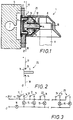
- the device 1 shown in FIGS. 1 and 4 for gripping an empty or winding-carrying sleeve 9 has a base body 2 which is fastened to a gripper bar 5 of a bobbin changing device of a spinning machine, which is known per se and is not shown in detail.
- a membrane 3 is located in the base body 2 and a clamping element 4 or 4 ', which can be pneumatically acted upon and is held in its illustrated starting position by a spring element 6.
- a sleeve 9 shown in broken lines, is clamped inside a housing 8.
- the clamping element 4 clamps the sleeve 9 between itself and an opposite stop 10 or 10 ′ arranged in the housing 8 and lifts it from its support (not shown in more detail), for example a spindle or a spool plate, during a subsequent upward movement of the gripper bar 5.
- the tensioning element 4 has a plate-like extension 11 in the rear region and is surrounded in the central region by a sleeve-like stop 12 which has contact surfaces 13 and 14 which are designed as contacts and are directed against the extension 11.
- the clamping element 4 forms an electromechanical sensor 25 in connection with its plate-like extension and the contact surfaces 13, 14 designed as contacts.
- lines 17 and 18 are provided on each device I or II or III etc. for gripping a sleeve, which lead to contacts 13 and 14 and are connected to signaling devices 15 and 16, for example designed as warning lamps .
- a contact point closed via the attachment 11 and the two contacts of the contact surfaces 13 and 14 thus shows either the machine side via a signal device 16 or the spinning point via a signal device 15, at which there is an irregularity.
- the doffing device can be shut down via the closed contact point.
- the contact 21 remains closed and, when one of the lines 17 or 18 is subjected to electrical voltage, supplies this voltage via the other line to the signaling device 15, 16.
- the processing of the given signals has to take this different contact into account.
Landscapes
- Engineering & Computer Science (AREA)
- Mechanical Engineering (AREA)
- Textile Engineering (AREA)
- Spinning Or Twisting Of Yarns (AREA)
Applications Claiming Priority (2)
| Application Number | Priority Date | Filing Date | Title |
|---|---|---|---|
| DE4037312A DE4037312C2 (de) | 1990-11-23 | 1990-11-23 | Vorrichtung zum Greifen einer leeren Hülse oder einer vollen Spule |
| DE4037312 | 1990-11-23 |
Publications (1)
| Publication Number | Publication Date |
|---|---|
| EP0486780A1 true EP0486780A1 (fr) | 1992-05-27 |
Family
ID=6418806
Family Applications (1)
| Application Number | Title | Priority Date | Filing Date |
|---|---|---|---|
| EP91115060A Withdrawn EP0486780A1 (fr) | 1990-11-23 | 1991-09-06 | Dispositif pour saisir un tube vide ou une bobine pleine |
Country Status (4)
| Country | Link |
|---|---|
| US (1) | US5203155A (fr) |
| EP (1) | EP0486780A1 (fr) |
| JP (1) | JPH04263630A (fr) |
| DE (1) | DE4037312C2 (fr) |
Cited By (1)
| Publication number | Priority date | Publication date | Assignee | Title |
|---|---|---|---|---|
| EP3388564A1 (fr) * | 2017-04-11 | 2018-10-17 | Kabushiki Kaisha Toyota Jidoshokki | Métier à filer à anneaux comprenant un dispositif de détection de défaillance lors de la levée |
Families Citing this family (4)
| Publication number | Priority date | Publication date | Assignee | Title |
|---|---|---|---|---|
| DE4132243C2 (de) * | 1991-09-27 | 1994-06-16 | Zinser Textilmaschinen Gmbh | Verfahren und Vorrichtung zum Betreiben einer Ringspinn- oder-zwirnmaschine |
| JP2002129434A (ja) * | 2000-10-17 | 2002-05-09 | Toyota Industries Corp | 単錘駆動式紡機の管替装置の異常検出方法及び装置 |
| CN103266369A (zh) * | 2013-05-09 | 2013-08-28 | 经纬纺织机械股份有限公司 | 环锭细纱机集体落纱防裂抓管器 |
| CH710261A1 (de) * | 2014-10-16 | 2016-04-29 | Rieter Ag Maschf | Befestigung für einen Doffergreifer. |
Citations (4)
| Publication number | Priority date | Publication date | Assignee | Title |
|---|---|---|---|---|
| CH348907A (de) * | 1956-02-27 | 1960-09-15 | Reiners Walter Ing Dr | Verfahren und Vorrichtung zum Kontrollieren von Garnwickeln vor deren Verarbeitung, z.B. in einer Spul- oder Webmaschine |
| DE2226077A1 (de) * | 1971-06-18 | 1972-12-28 | Maschinenfabrik Rieter Ag, Winterthur (Schweiz) | Verfahren und Vorrichtung zum Überwachen eines Auswechselns von Kopsen gegen Hülsen auf Spindeln an Ringspinn- und Ringzwirnmaschinen |
| EP0365751A2 (fr) * | 1988-10-25 | 1990-05-02 | Zinser Textilmaschinen GmbH | Appareil de transport pour amener automatiquement des enroulements de nappe à plusieurs machines de peignage |
| DE4030623A1 (de) * | 1989-09-28 | 1991-04-11 | Murata Machinery Ltd | Fadenzufuehrvorrichtung fuer einen spulautomaten |
Family Cites Families (9)
| Publication number | Priority date | Publication date | Assignee | Title |
|---|---|---|---|---|
| NL134992C (fr) * | 1968-08-05 | |||
| DE2231377C3 (de) * | 1972-06-27 | 1979-08-02 | Zinser Textilmaschinen Gmbh, 7333 Ebersbach | Selbsttätige Hülsenwechseleinrichtung an einer Spinn- oder Zwirnmaschine |
| US4036001A (en) * | 1975-03-31 | 1977-07-19 | Kabushiki Kaisha Toyoda Jidoshokki Seisakusho | Method and apparatus for doffing and donning bobbins in spinning machine |
| JPS5647169Y2 (fr) * | 1979-02-10 | 1981-11-05 | ||
| JPS5874468A (ja) * | 1981-10-28 | 1983-05-04 | Howa Mach Ltd | 満ボビン抜揚装置 |
| JPS59173320A (ja) * | 1983-03-18 | 1984-10-01 | Toyoda Autom Loom Works Ltd | 精紡機等の管替え装置におけるボビン確認装置 |
| US5014505A (en) * | 1987-08-18 | 1991-05-14 | Rieter Machine Works, Ltd. | Apparatus for changing bobbin tubes and tube gripper therefor |
| DE3836330A1 (de) * | 1988-10-25 | 1990-04-26 | Zinser Textilmaschinen Gmbh | Verfahren und vorrichtung zum ueberwachen des erfassens bzw. freigebens aller huelsen bzw. spulen einer selbsttaetigen spulenwechselvorrichtung an einer ringspinn- oder -zwirnmaschine |
| DE3912332A1 (de) * | 1989-04-14 | 1990-10-18 | Zinser Textilmaschinen Gmbh | Spulengreifvorrichtung |
-
1990
- 1990-11-23 DE DE4037312A patent/DE4037312C2/de not_active Expired - Fee Related
-
1991
- 1991-09-06 EP EP91115060A patent/EP0486780A1/fr not_active Withdrawn
- 1991-11-22 JP JP3307857A patent/JPH04263630A/ja not_active Withdrawn
- 1991-11-25 US US07/799,820 patent/US5203155A/en not_active Expired - Fee Related
Patent Citations (4)
| Publication number | Priority date | Publication date | Assignee | Title |
|---|---|---|---|---|
| CH348907A (de) * | 1956-02-27 | 1960-09-15 | Reiners Walter Ing Dr | Verfahren und Vorrichtung zum Kontrollieren von Garnwickeln vor deren Verarbeitung, z.B. in einer Spul- oder Webmaschine |
| DE2226077A1 (de) * | 1971-06-18 | 1972-12-28 | Maschinenfabrik Rieter Ag, Winterthur (Schweiz) | Verfahren und Vorrichtung zum Überwachen eines Auswechselns von Kopsen gegen Hülsen auf Spindeln an Ringspinn- und Ringzwirnmaschinen |
| EP0365751A2 (fr) * | 1988-10-25 | 1990-05-02 | Zinser Textilmaschinen GmbH | Appareil de transport pour amener automatiquement des enroulements de nappe à plusieurs machines de peignage |
| DE4030623A1 (de) * | 1989-09-28 | 1991-04-11 | Murata Machinery Ltd | Fadenzufuehrvorrichtung fuer einen spulautomaten |
Non-Patent Citations (1)
| Title |
|---|
| PATENT ABSTRACTS OF JAPAN vol. 7, no. 169 (M-231)(1314) 26. Juli 1983 & JP-A-58 074 468 ( HOWA KOGYO K.K. ) 4. Mai 1983 * |
Cited By (1)
| Publication number | Priority date | Publication date | Assignee | Title |
|---|---|---|---|---|
| EP3388564A1 (fr) * | 2017-04-11 | 2018-10-17 | Kabushiki Kaisha Toyota Jidoshokki | Métier à filer à anneaux comprenant un dispositif de détection de défaillance lors de la levée |
Also Published As
| Publication number | Publication date |
|---|---|
| JPH04263630A (ja) | 1992-09-18 |
| DE4037312C2 (de) | 1994-03-10 |
| DE4037312A1 (de) | 1992-05-27 |
| US5203155A (en) | 1993-04-20 |
Similar Documents
| Publication | Publication Date | Title |
|---|---|---|
| DE3701796A1 (de) | Verfahren und vorrichtung zum einsatzsteuern von bedienorganen an einer spinnereianlage | |
| CH657160A5 (de) | Verfahren und vorrichtung zur betriebsueberwachung an einer arbeitsstelle einer spinn- oder zwirnmaschine und zur stillsetzung einer solchen arbeitsstelle bei laufstoerungen. | |
| DE2525560A1 (de) | Verfahrbare wartungseinrichtung fuer offenend-spinnmaschinen | |
| DE4209203B4 (de) | Spinn-/Spulmaschinenkombination mit einer Vorrichtung zum Überwachen des ordnungsgemäßen Arbeitens der einzelnen Spinnstellen | |
| DE3711793C2 (fr) | ||
| EP0392249B1 (fr) | Système d'information dans une connexion entre un ou plusieurs métiers à filer ou machines de bobinage | |
| DE3644433C2 (de) | Verfahren und Vorrichtung zum Steuern einer Spulstelle einer Kreuzspulen herstellenden Textilmaschine | |
| DE1930180A1 (de) | Automatische Spulmaschine | |
| EP3241794A1 (fr) | Procédé de manipulation d'une extrémité de fil et poste de bobinage | |
| DE3026075C2 (de) | Spulenwechselvorrichtung an Spinnmaschinen | |
| EP0366048B1 (fr) | Procédé et dispositif pour surveiller les préhension et relâchement de tous les tubes respectivement de toutes les bobines d'un appareil d'échange automatique de bobines d'un métier à filer à anneaux ou d'un métier à retordre à anneaux | |
| DE4037312A1 (de) | Vorrichtung zum greifen einer leeren huelse oder einer vollen spule | |
| DE19636661A1 (de) | Transportsystem für eine Textilmaschine | |
| DE2224688A1 (de) | Vorrichtung zum durchtrennen eines von einem vorrat zulaufenden garnfadens | |
| CH676861A5 (fr) | ||
| DE2552448A1 (de) | Verfahren und vorrichtung zur voruebergehenden ausserbetriebnahme von spinnstellen | |
| DE2836717C3 (de) | Positive Fadenliefervorrichtung für Textilmaschinen | |
| EP0095709A1 (fr) | Fournisseur de fil pour un métier à tricoter avec rayeur | |
| DE4132243C2 (de) | Verfahren und Vorrichtung zum Betreiben einer Ringspinn- oder-zwirnmaschine | |
| EP0905294B1 (fr) | Surveillance de garnissage dans une machine de préparation à la filature | |
| DE4037880C2 (de) | Verfahren und Vorrichtung zum Überwachen des Spulenwechselvorganges bei einer Spinnereimaschine | |
| DE102018008062A1 (de) | Verfahren zum Bedienen einer Schmelzspinnvorrichtung sowie eine Schmelzspinnvorrichtung | |
| DE3941822C2 (de) | Vorrichtung zum Wechseln von Vorgarnspulen | |
| DE2722895C3 (de) | Automatischer Spulenwechsler für eine Spinnmaschine o.dgl | |
| EP0276470B1 (fr) | Dispositif pour contrôler la réserve de fil sur bobines |
Legal Events
| Date | Code | Title | Description |
|---|---|---|---|
| PUAI | Public reference made under article 153(3) epc to a published international application that has entered the european phase |
Free format text: ORIGINAL CODE: 0009012 |
|
| AK | Designated contracting states |
Kind code of ref document: A1 Designated state(s): CH DE FR IT LI |
|
| 17P | Request for examination filed |
Effective date: 19921015 |
|
| STAA | Information on the status of an ep patent application or granted ep patent |
Free format text: STATUS: THE APPLICATION IS DEEMED TO BE WITHDRAWN |
|
| 18D | Application deemed to be withdrawn |
Effective date: 19940401 |