EP0487013A1 - Process and apparatus to identify the presence of structural cavities in sleeves for the manufacture of driving belts - Google Patents
Process and apparatus to identify the presence of structural cavities in sleeves for the manufacture of driving belts Download PDFInfo
- Publication number
- EP0487013A1 EP0487013A1 EP91119688A EP91119688A EP0487013A1 EP 0487013 A1 EP0487013 A1 EP 0487013A1 EP 91119688 A EP91119688 A EP 91119688A EP 91119688 A EP91119688 A EP 91119688A EP 0487013 A1 EP0487013 A1 EP 0487013A1
- Authority
- EP
- European Patent Office
- Prior art keywords
- sleeve
- receiving member
- emitting
- ultrasonic emitting
- structural cavities
- Prior art date
- Legal status (The legal status is an assumption and is not a legal conclusion. Google has not performed a legal analysis and makes no representation as to the accuracy of the status listed.)
- Withdrawn
Links
- 238000000034 method Methods 0.000 title claims description 26
- 230000008569 process Effects 0.000 title claims description 23
- 238000004519 manufacturing process Methods 0.000 title claims description 19
- 238000012545 processing Methods 0.000 claims abstract description 40
- 230000033001 locomotion Effects 0.000 claims description 17
- 238000001514 detection method Methods 0.000 claims description 11
- 239000013536 elastomeric material Substances 0.000 claims description 11
- 230000000875 corresponding effect Effects 0.000 claims description 9
- 230000002596 correlated effect Effects 0.000 claims description 5
- 239000011247 coating layer Substances 0.000 claims description 3
- 238000006073 displacement reaction Methods 0.000 claims description 3
- GNFTZDOKVXKIBK-UHFFFAOYSA-N 3-(2-methoxyethoxy)benzohydrazide Chemical compound COCCOC1=CC=CC(C(=O)NN)=C1 GNFTZDOKVXKIBK-UHFFFAOYSA-N 0.000 claims description 2
- YTAHJIFKAKIKAV-XNMGPUDCSA-N [(1R)-3-morpholin-4-yl-1-phenylpropyl] N-[(3S)-2-oxo-5-phenyl-1,3-dihydro-1,4-benzodiazepin-3-yl]carbamate Chemical compound O=C1[C@H](N=C(C2=C(N1)C=CC=C2)C1=CC=CC=C1)NC(O[C@H](CCN1CCOCC1)C1=CC=CC=C1)=O YTAHJIFKAKIKAV-XNMGPUDCSA-N 0.000 claims description 2
- 230000001747 exhibiting effect Effects 0.000 claims 2
- FGUUSXIOTUKUDN-IBGZPJMESA-N C1(=CC=CC=C1)N1C2=C(NC([C@H](C1)NC=1OC(=NN=1)C1=CC=CC=C1)=O)C=CC=C2 Chemical compound C1(=CC=CC=C1)N1C2=C(NC([C@H](C1)NC=1OC(=NN=1)C1=CC=CC=C1)=O)C=CC=C2 FGUUSXIOTUKUDN-IBGZPJMESA-N 0.000 claims 1
- 238000007689 inspection Methods 0.000 description 10
- 238000012360 testing method Methods 0.000 description 9
- 239000010410 layer Substances 0.000 description 6
- 230000015572 biosynthetic process Effects 0.000 description 5
- 238000005520 cutting process Methods 0.000 description 5
- 238000005755 formation reaction Methods 0.000 description 5
- 239000011265 semifinished product Substances 0.000 description 4
- 238000004073 vulcanization Methods 0.000 description 4
- 239000000463 material Substances 0.000 description 3
- 239000000203 mixture Substances 0.000 description 3
- 230000007547 defect Effects 0.000 description 2
- 230000002950 deficient Effects 0.000 description 2
- 230000001771 impaired effect Effects 0.000 description 2
- 230000008595 infiltration Effects 0.000 description 2
- 238000001764 infiltration Methods 0.000 description 2
- 238000003908 quality control method Methods 0.000 description 2
- 230000000007 visual effect Effects 0.000 description 2
- 230000009471 action Effects 0.000 description 1
- 230000004913 activation Effects 0.000 description 1
- 230000004075 alteration Effects 0.000 description 1
- 238000010073 coating (rubber) Methods 0.000 description 1
- 238000011161 development Methods 0.000 description 1
- 238000010586 diagram Methods 0.000 description 1
- 229920001971 elastomer Polymers 0.000 description 1
- 239000000806 elastomer Substances 0.000 description 1
- 230000008030 elimination Effects 0.000 description 1
- 238000003379 elimination reaction Methods 0.000 description 1
- 238000011156 evaluation Methods 0.000 description 1
- 238000010438 heat treatment Methods 0.000 description 1
- 238000012986 modification Methods 0.000 description 1
- 230000004048 modification Effects 0.000 description 1
- 230000002787 reinforcement Effects 0.000 description 1
- 230000011664 signaling Effects 0.000 description 1
- 238000013519 translation Methods 0.000 description 1
Images

Classifications
-
- B—PERFORMING OPERATIONS; TRANSPORTING
- B29—WORKING OF PLASTICS; WORKING OF SUBSTANCES IN A PLASTIC STATE IN GENERAL
- B29D—PRODUCING PARTICULAR ARTICLES FROM PLASTICS OR FROM SUBSTANCES IN A PLASTIC STATE
- B29D29/00—Producing belts or bands
-
- G—PHYSICS
- G01—MEASURING; TESTING
- G01N—INVESTIGATING OR ANALYSING MATERIALS BY DETERMINING THEIR CHEMICAL OR PHYSICAL PROPERTIES
- G01N29/00—Investigating or analysing materials by the use of ultrasonic, sonic or infrasonic waves; Visualisation of the interior of objects by transmitting ultrasonic or sonic waves through the object
- G01N29/22—Details, e.g. general constructional or apparatus details
- G01N29/26—Arrangements for orientation or scanning by relative movement of the head and the sensor
- G01N29/275—Arrangements for orientation or scanning by relative movement of the head and the sensor by moving both the sensor and the material
-
- G—PHYSICS
- G01—MEASURING; TESTING
- G01N—INVESTIGATING OR ANALYSING MATERIALS BY DETERMINING THEIR CHEMICAL OR PHYSICAL PROPERTIES
- G01N29/00—Investigating or analysing materials by the use of ultrasonic, sonic or infrasonic waves; Visualisation of the interior of objects by transmitting ultrasonic or sonic waves through the object
- G01N29/04—Analysing solids
- G01N29/11—Analysing solids by measuring attenuation of acoustic waves
-
- G—PHYSICS
- G01—MEASURING; TESTING
- G01N—INVESTIGATING OR ANALYSING MATERIALS BY DETERMINING THEIR CHEMICAL OR PHYSICAL PROPERTIES
- G01N29/00—Investigating or analysing materials by the use of ultrasonic, sonic or infrasonic waves; Visualisation of the interior of objects by transmitting ultrasonic or sonic waves through the object
- G01N29/22—Details, e.g. general constructional or apparatus details
- G01N29/24—Probes
- G01N29/2493—Wheel shaped probes
-
- G—PHYSICS
- G01—MEASURING; TESTING
- G01N—INVESTIGATING OR ANALYSING MATERIALS BY DETERMINING THEIR CHEMICAL OR PHYSICAL PROPERTIES
- G01N2291/00—Indexing codes associated with group G01N29/00
- G01N2291/02—Indexing codes associated with the analysed material
- G01N2291/028—Material parameters
- G01N2291/02854—Length, thickness
-
- G—PHYSICS
- G01—MEASURING; TESTING
- G01N—INVESTIGATING OR ANALYSING MATERIALS BY DETERMINING THEIR CHEMICAL OR PHYSICAL PROPERTIES
- G01N2291/00—Indexing codes associated with group G01N29/00
- G01N2291/04—Wave modes and trajectories
- G01N2291/048—Transmission, i.e. analysed material between transmitter and receiver
-
- G—PHYSICS
- G01—MEASURING; TESTING
- G01N—INVESTIGATING OR ANALYSING MATERIALS BY DETERMINING THEIR CHEMICAL OR PHYSICAL PROPERTIES
- G01N2291/00—Indexing codes associated with group G01N29/00
- G01N2291/10—Number of transducers
- G01N2291/102—Number of transducers one emitter, one receiver
-
- G—PHYSICS
- G01—MEASURING; TESTING
- G01N—INVESTIGATING OR ANALYSING MATERIALS BY DETERMINING THEIR CHEMICAL OR PHYSICAL PROPERTIES
- G01N2291/00—Indexing codes associated with group G01N29/00
- G01N2291/26—Scanned objects
- G01N2291/269—Various geometry objects
Definitions
- the present invention relates to a process and an apparatus to identify the presence of structural cavities in sleeves for the manufacture of driving belts.
- the invention is adapted to carry out quality control tests on sleeves for the production of driving belts of different kinds, such as toothed belts, flat grooved belts, toothed V-belts and so on.
- toothed belts are obtained by a cutting operation carried out according to several circumferential lines on a cylindrical tubular sleeve having a toothed inner surface.
- This sleeve is made by wrapping at least a reinforcement layer incorporating a plurality of inextensible cords around a cylindrical grooved die negatively reproducing the toothing extension, on which one or more layers of elastomeric material are then superposed.
- the semifinished product thus obtained is then submitted to a vulcanization process in an autoclave.
- the semifinished product previously enclosed in a rubber coating sheath, undergoes a suitable heating by means of steam under pressure which is sent into the die and to the outside of the sheath surrounding the semifinished product.
- the layers of elastomeric material are submitted to homogeneously-distributed centripetal compressive forces urging the elastomeric material to forcedly pass through the inextensible cord layer.
- the elastomeric material will fill the grooves provided in the die, thereby creating the inner toothing on the finished sleeve.
- cavities can also take place for other reasons, for example due to the development of gas for a wrong composition of the materials forming the elastomeric layers.
- the cavities can be of very reduced sizes, having a diameter smaller than half a millimeter.
- the mere visual evaluation of the toothed surface enables only cavities appearing on the surface itself to be identified, without offering the possibility of detecting those cavities that are incorporated internally in the elastomeric material.
- the main object of the present invention is substantially to solve the problems of the known art, by a process and an apparatus enabling an accurate and reliable inspection of the toothing.
- a further object of the invention is to provide a process and an apparatus capable of identifying and signalling the presence of structural cavities in the toothing in a very timely manner, when they are due to a bad operation of the apparatuses adopted in the vulcanization processes or to wrong compositions of the materials used for the manufacture of the sleeves, in order to allow immediate interventions for the elimination of these anomalies.
- an apparatus for identifying the presence of structural cavities in sleeves for the manufacture of driving belts characterized in that it comprises:
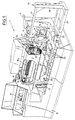
- FIG. 1 an apparatus for identifying the presence of structural cavities in sleeves for the manufacture of driving belts in accordance with the invention has been generally denoted by reference numeral 1.
- apparatus 1 lends itself to act on sleeves 2 of the type used for the manufacture of toothed belts.
- Each sleeve 2 is provided with a toothed inner surface 2a having a plurality of shaped teeth 3 disposed parallelly to one another in side by side relation according to a predetermined spacing "P".
- the configuration of the teeth 3 can be various depending upon the cases.
- apparatus 1 lends itself to perform the identification of the structural cavities 3a by a process that, in a preferential solution, essentially comprises the following steps:
- apparatus 1 substantially comprises a bed 4 on which supporting means 5, 6, 10 is mounted which is arranged to operatively support the toothed element 2.
- the supporting means is comprised of at least an upper roller 5 rotatably engaged to the bed 4 and at least a lower roller 6 parallel to the upper roller 5 and operatively engaged to a supporting column 7 movable, upon command of fluid-operated actuators 8 or similar means, to enable the lower roller 6 to move close to and away from the upper roller 5.
- two upper rollers 5 and two lower rollers 6 are provided and they are disposed in side by side relation according to substantially horizontal planes.
- auxiliary lower roller 10 disposed parallelly under the lower rollers 6.
- the auxiliary roller 10 is adapted to be used in place of the lower rollers 6 when the sleeves 2 being worked exhibit a large circumferential extension.
- the motion-imparting means consisting of at least a first motor 9 acting on at least one of the upper rollers 5 to impart a continuous movement to the sleeve 2 in a direction substantially perpendicular to the longitudinal extension of the teeth 3 provided thereon.
- each of the supporting rollers 5, 6, 10 is provided with a coating layer made of elastomeric material 5b, 6b, 10b in order to ensure a firm grip on the toothed surface 2a and an easy adaptability to the different types of sleeves 2 being worked.
- At least one of the ends 5a of each upper roller 5 can be operatively engaged by a first removable support 11 slidably guided relative to the bed 4 and laterally movable apart from the upper rollers, upon command of fluid-operated cylinders 12 or the like, to enable the sleeve 2 to be engaged thereabout, as clearly shown in Fig. 1.
- At least one of the ends 6a, 10a of each of the lower rollers 6 and auxiliary roller 10 can be operatively engaged by a second removable support 13 connected to a side extension 7a of the supporting column 7 and movable laterally apart from the lower rollers upon command of respective actuators 14.
- Apparatus 1 is provided with at least an ultrasonic emitting and receiving member, generally denoted by 15, designed to operate through the sleeve 2 at a first read point "X", in order to detect the presence of structural cavities 3a.
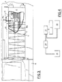
- the ultrasonic emitting and receiving member comprises an ultrasonic emitting part 15a and an ultrasonic receiving part 15b facing each other in mutual alignment and acting by means of respective rollers 16a, 16b in sliding contact relationship on the inner surface 2a and the outer surface 2b respectively, or at all events two opposite surfaces, of the sleeve 2.
- At least the emitting part 15a is submitted to an elastic thrust action upon command of a preloading spring 17 ensuring the contact thereof with the outline of the teeth 3.
- the emitting part 15a and the receiving part 15b are fastened to respective telescopic bars 18a, 18b simultaneously extensible upon command of second motion-imparting means consisting for example of at least a threaded bar, not shown as known and conventional, set in rotation by a second motor 19.
- the ultrasonic emitting and receiving member 15 is capable of sending, by means of the emitting part 15a, ultrasonic signals of an appropriate frequency through the sleeve 2 towards the receiving part 15b.
- the frequency of the ultrasonic waves should have a value in the range of 0.3 MHz to 0.5 MHz.
- the receiving part 15b in turn is capable of sensing the signals sent from the emitting part 15a and consequently emit electric signals correlated with the ultrasonic reception signal.
- the ultrasonic waves In the absence of structural discontinuities in the sleeve 2, the ultrasonic waves easily pass through the elastomeric material interposed between the emitting part 15a and the receiving part 15b and can be therefore clearly sensed by the receiving part.
- one or more structural cavities 3a are incorporated in the elastomeric material in the regions passed through by the ultrasonic waves, that is at the first read point "X"
- the travel of the ultrasonic waves is greatly hindered and, as a result, said waves will not be senses by the receiving part 15a or will be sensed to a very reduced degree.
- the emitting and receiving member 15 are connected to an electronic processing unit 20.
- An electronic control box 21 (Fig. 4) of the type commonly named PLC, controls the sequential operation of the various members associated with apparatus 1 (motors 9, 19, actuator cylinders 8, 12, 14, and so on).
- the processing unit 20 preferably consisting of a conventional personal computer, in accordance with modalities to be clarified in the following, processes signals received by the ultrasonic emitting and receiving member 15 in order to identify the position of the structural cativites 3a on the longitudinal extension of the sleeve 2.
- a reading member 22 preferably of the laser beam type, fastened to one end of the telescopic bar 18a engaging the emitting part 15a.
- the reading member 22 sends a light beam "R" onto the toothed surface 2a of the sleeve 2 and, by picking up the reflected light from the struck surface at a second read point "Y" adjacent the first reading point "X", is capable of emitting electric signals correlated to the distance between the reading member and the second read point "Y" struck by the light beam "R".
- the reading member 22 which is connected to the electronic processing unit 20 as well upon interposition of the electronic control box 21, is used to inspect the geometrical configuration of the toothed surface 2a, in accordance with a process being the object of a parallel patent application filed in the name of the same Applicant.
- the processing unit 20 processes signals received from the reading member 22 in order to draw data relating to the geometrical configuration of the toothed surface 2a therefrom, which data are then compared with theoretical geometric parameters previously stored in the processing unit.
- the reading member 22 is used to enable the electronic processing unit 20 to know the position of the first read point "X", instant by instant, on the outline of the toothed surface 2a.
- this expedient aims at permitting the processing unit 20 to disenable indifferently either the emission or the reception of signals by the ultrasonic emitting and receiving member 15 each time the first read point "X" is located in a region of the toothed surface 2a included between two contiguous teeth 3.
- the disenabling area in the longitudinal section of the belt in Fig. 2 can be identified by the distance between the points of two teeth in the belt determined by the meeting between the connecting radius at the tooth root and the beginning of the flank.
- Theoretical geometric parameters corresponding to the toothed surfaces 2a of different types of sleeves 2 produced in the factory in which apparatus 1 is installed are input to the memory of the processing unit 20.
- An individual code is then assigned to the theoretical geometric parameters of each type of toothed surface 2a which code will enable the immediate selective recalling of said parameters for carrying out the operating steps of apparatus 1.
- the individual code corresponding to the sleeve 2 being tested is detected by the electronic control box 21 when the sleeve is fitted on the rollers 5, 6.
- an automatic read and record head 24 is conventionally interlocked to the electronic control box 21, which head is designed to detect the information recorded on a corresponding proper card 25 associated with a handling support 26 conventionally used to transport the sleeves 2 and the belts subsequently produced between the various work stations inside the factory.
- the head 24 and the card 25 are magnetic.
- the above handling support 26 holds the sleeve 2 by means of a bar 27 fastened in cantilevered fashion to a post 28 standing up from a base framework 29.
- the handling support 26 lends itself to be operatively engaged along a roller-bed 30 mounted to the lower part of the apparatus bed 4, in order to fit the sleeve 3 on the rollers 5, 6 located close to each other, while the magnetic card 25 is simultaneously brought under the read head 24.
- the electronic control box 21 can transmit the individual code recorded on the magnetic card 25 carried by the handling support 26, to the processing unit 20.
- the sleeve 2 is laid on the upper rollers 5, for example by lowering the roller-bed 30, then the handling support 26 is unthreaded from the sleeve, as shown in Fig. 1, to operatively engage with the ends 5a, 6a, 10a of the upper and lower rollers 5 and 6, 10.
- the processing unit 20 has found in its memory the theoretical geometric parameters corresponding to the individual code signalled to it. Therefore the processing unit 20 causes, through the activation of the electronic control box 21, the lowering of the lower rollers 6, 10 to an extent sufficient to produce a given tensioning of the sleeve 2.
- an inspection step can be provided, through measuring means associated with the supporting column 7, in order to verify whether the carried out positioning of the lower rollers 6, 10 corresponds to the expected tensioning of the sleeve 2.
- apparatus 1 begins the process for identifying the structural cavities 3a in the sleeve 2, which process, in accordance with the present invention, takes place following the modalities set forth hereinafter.
- the processing unit 20 enables the electronic control box 21 to actuate the first motor 9 which, through the upper rollers 5, sets in motion the sleeve 2 in a direction transverse to the extension of the teeth 3.
- the second motor 19 is actuated as well, and it causes the translation of the ultrasonic emitting and receiving member 15 and the reading member 22 in a direction substantially parallel to the longitudinal extension of the teeth 3, according to a predetermined speed.
- the starting motion point of the emitting and receiving member 15 and the reading member 22 is located laterally apart from the sleeve 2, so that the movement speeds of the sleeve and of said members 15, 22 may be stabilized before the process for the identification of cavities 3a really begins.
- the processing unit 20 may be capable of periodically disenabling the ultrasonic emitting and receiving member 15 for the above clarified purposes, it is necessary for the processing unit to know the exact position of the first read point "X" relative to the individual teeth 3.
- the processing unit 20 based on signals coming from the reading member 22, identifies the transverse outline of the toothed surface 2a by means of repeated detections of the height "h" exhibited, instant by instant, by the toothed surface at the second read point "Y".
- the processing unit 20 times the interval of time intervening between the different detections of the height values "h".
- the processing unit 20 also carries out the identification of the passage, under the second read point "Y", of two identical characteristic points "K" each belonging to the transverse outline of one of the teeth 3.
- These characteristinc points "K” that in the described embodiment are constituted by a recess 3b formed on top of each tooth 3 and having a predetermined height "H”, are unmistakably spaced apart from each other by a known amount previously stored in the processing unit 20, which amount is preferably the same as the spacing "P" of teeth 3.
- the processing unit 20 is capable of establishing the displacement of the toothed surface 2a relative to the read points "X" and "Y” expressed as the space/time ratio resulting when the value of spacing "P" is divided by the value of the interval of time.
- the processing unit 20 assigns to each height value "h” detected during the repeated reading step, a corresponding distance value "L” from one of the characteristic points "K", based on the interval of time intervening between the detection of the height value and the detection of the passage of said characteristic point "K".
- the processing unit 20 is capable of knowing the exact frequency of passage of the teeth 3 before the first read point "X” and can consequently stop the cavity detection step carried out by the ultrasonic emitting and receiving member 15 each time the first read point "X" falls on the area of the toothed surface 2a included between two contiguous teeth 3.
- the identification of the interval of time intervening between the passage of the characteristic points "K" is preferably repeated twice or three times consecutively, each referred to two different teeth 3, as far as the processing unit 20 finds a constant time value for a predetermined number of times between one measuring and the next one.
- the operating steps for detecting the space/time ratio be carried out several times at predetermined intervals during the inspection test on the sleeve 2.
- test result is not impaired by possible variations in the relative speed between the toothed surface 2a and the read points "X" and "Y", caused for example either by uncontrolled variations in the running speed of the first and/or second motor 9, 19, or slight elastic de formations of the sleeve 2 and/or the elastomeric coating layers disposed on the rollers 5, 6, 10, or by an imperfect parallelism between the individual teeth 3 and the direction of movement of the emitting and receiving member 15 and the reading member 22.
- the processing unit 20 identifies which of the belts to be produced in the following cutting operation on the sleeve 2 will have the defective tooth 3.
- the processing unit 20 should preferably know the width of the single belts to be produced and be able to carry out the above operation based on the movement speed of the reading member 22 and the interval of time elapsed from the moment that the identification step by the ultrasonic emitting and receiving member has started to the moment at which the presence of cavities 3a is detected.
- the processing unit 20 will send signals relating to the position of the cavities 3a to the magnetic card 25, through the electronic control box 21 and the read and record head 24.
- Signals input to the magnetic card 25 will enable other automatic machines provided in the belt production cycle to identify and discard the belts that after the subsequent cutting operation of the sleeve, will have defective teeth.
- the process in accordance with the invention also enables timely interventions in order to eliminate the causes that have led to the formation of the structural cavities 3a.
- the processing unit 20 is provided to be able to transmit all data detected during the test to a processor 31.
- the processor 31 supervising the operation of the main apparatuses used in the belt production cycle will signal the operating anomaly of the apparatus or apparatuses in which the formation of cavities 3a is supposed to have had origin.
- the present invention attains the intended purposes.
- the inventive apparatus also enables cavities of very reduced sizes and completely incorporated in the elastomeric material to be detected.
- the emitting member can be replaced by equivalent elements adapted to send signals, waves and the like the intensity of which could be sensed by the receiving member to a different extent depending upon the presence or absence of cavities in the elastomeric material of the belt.
- the described method can also apply to the identification of cavities located other than in the teeth, for example on elastomeric portions between the tooth base line and the belt back.
Landscapes
- Physics & Mathematics (AREA)
- Immunology (AREA)
- Health & Medical Sciences (AREA)
- Chemical & Material Sciences (AREA)
- Analytical Chemistry (AREA)
- Biochemistry (AREA)
- General Health & Medical Sciences (AREA)
- Life Sciences & Earth Sciences (AREA)
- Pathology (AREA)
- General Physics & Mathematics (AREA)
- Acoustics & Sound (AREA)
- Engineering & Computer Science (AREA)
- Mechanical Engineering (AREA)
- Investigating Or Analyzing Materials By The Use Of Ultrasonic Waves (AREA)
- Package Frames And Binding Bands (AREA)
- Structure Of Belt Conveyors (AREA)
Applications Claiming Priority (2)
| Application Number | Priority Date | Filing Date | Title |
|---|---|---|---|
| IT2212690 | 1990-11-21 | ||
| IT02212690A IT1244018B (it) | 1990-11-21 | 1990-11-21 | Proedimento ed apparecchiatura per individuare la presenza di cavita' strutturali in manicotti per la realizzazione di cinghie di trasmissione. |
Publications (1)
| Publication Number | Publication Date |
|---|---|
| EP0487013A1 true EP0487013A1 (en) | 1992-05-27 |
Family
ID=11191881
Family Applications (1)
| Application Number | Title | Priority Date | Filing Date |
|---|---|---|---|
| EP91119688A Withdrawn EP0487013A1 (en) | 1990-11-21 | 1991-11-19 | Process and apparatus to identify the presence of structural cavities in sleeves for the manufacture of driving belts |
Country Status (5)
| Country | Link |
|---|---|
| US (1) | US5311778A (it) |
| EP (1) | EP0487013A1 (it) |
| JP (1) | JPH04291148A (it) |
| KR (1) | KR920009549A (it) |
| IT (1) | IT1244018B (it) |
Families Citing this family (1)
| Publication number | Priority date | Publication date | Assignee | Title |
|---|---|---|---|---|
| US10014561B2 (en) | 2013-08-15 | 2018-07-03 | University Of Maryland, College Park | Systems, methods, and devices for health monitoring of an energy storage device |
Citations (4)
| Publication number | Priority date | Publication date | Assignee | Title |
|---|---|---|---|---|
| US4018082A (en) * | 1974-12-30 | 1977-04-19 | Institutul Pentru Creatie Stintifica Si Tehnica-Increst | Device for nondestructive ultrasonic testing of cylindrical parts |
| US4274289A (en) * | 1979-08-29 | 1981-06-23 | Amf Incorporated | Transducer positioning system for ultrasonic tire testing apparatus |
| US4577502A (en) * | 1981-06-29 | 1986-03-25 | Mount Isa Mines Limited | Conveyor belt monitor |
| US4750368A (en) * | 1987-05-26 | 1988-06-14 | Weyerhaeuser Company | Bond strength measurement of composite panel products |
Family Cites Families (4)
| Publication number | Priority date | Publication date | Assignee | Title |
|---|---|---|---|---|
| DE2920142C2 (de) * | 1979-05-18 | 1982-11-25 | Krautkrämer, GmbH, 5000 Köln | Ultraschall-Prüfanlage zur Ermittlung von Fehlern in Rohren |
| US4596953A (en) * | 1982-04-14 | 1986-06-24 | Daidotokushuko Kabushikikaisha | Apparatus for scanning a material for detection of flaws and having material axis deviation detection |
| US4599900A (en) * | 1984-01-03 | 1986-07-15 | Automation Industries, Inc. | Workpiece for handling apparatus for nondestructive testing |
| US4562738A (en) * | 1984-04-04 | 1986-01-07 | Mitsubishi Denki Kabushiki Kaisha | Automatic flaw detection device |
-
1990
- 1990-11-21 IT IT02212690A patent/IT1244018B/it active IP Right Grant
-
1991
- 1991-11-19 EP EP91119688A patent/EP0487013A1/en not_active Withdrawn
- 1991-11-21 KR KR1019910020879A patent/KR920009549A/ko not_active Withdrawn
- 1991-11-21 JP JP3306284A patent/JPH04291148A/ja active Pending
- 1991-11-21 US US07/793,733 patent/US5311778A/en not_active Expired - Fee Related
Patent Citations (4)
| Publication number | Priority date | Publication date | Assignee | Title |
|---|---|---|---|---|
| US4018082A (en) * | 1974-12-30 | 1977-04-19 | Institutul Pentru Creatie Stintifica Si Tehnica-Increst | Device for nondestructive ultrasonic testing of cylindrical parts |
| US4274289A (en) * | 1979-08-29 | 1981-06-23 | Amf Incorporated | Transducer positioning system for ultrasonic tire testing apparatus |
| US4577502A (en) * | 1981-06-29 | 1986-03-25 | Mount Isa Mines Limited | Conveyor belt monitor |
| US4750368A (en) * | 1987-05-26 | 1988-06-14 | Weyerhaeuser Company | Bond strength measurement of composite panel products |
Also Published As
| Publication number | Publication date |
|---|---|
| IT1244018B (it) | 1994-06-28 |
| KR920009549A (ko) | 1992-06-25 |
| IT9022126A1 (it) | 1992-05-22 |
| JPH04291148A (ja) | 1992-10-15 |
| IT9022126A0 (it) | 1990-11-21 |
| US5311778A (en) | 1994-05-17 |
Similar Documents
| Publication | Publication Date | Title |
|---|---|---|
| US6122065A (en) | Apparatus and method for detecting surface defects | |
| JP4854839B2 (ja) | 機械診断方法と装置 | |
| CN109612425A (zh) | 一种转子视觉测量机 | |
| EP0487015B1 (en) | A process and apparatus for inspecting the geometrical configuration of toothed driving elements | |
| US5311778A (en) | Process and apparatus to identify the presence of structural cavities in sleeves for the manufacture of driving belts | |
| KR100638283B1 (ko) | 타이어 트레드 자동 조인트 감지장치 | |
| EP2293012B1 (en) | Method and device to control the torsions of long products | |
| KR102063706B1 (ko) | 샤프트의 위치 변환용 지그부를 구비하는 차량용 샤프트 이송 및 검사 장치 및 샤프트의 위치 변환용 지그부 | |
| US5239184A (en) | Process and machine for spotting superficial defects on layers and/or sleeves of elastomeric material | |
| US4280094A (en) | Test plate method and an arrangement for testing the serviceability and for setting and calibrating a test apparatus for the non-destructive electrical or magnetic testing of metallic blanks | |
| KR20210152708A (ko) | 할로우핀 측정장치 | |
| JP5413970B2 (ja) | 複数のパイプ部材の測定装置及び方法 | |
| CN209577445U (zh) | 一种3c产品尺寸检测设备 | |
| JPH06160354A (ja) | スチールコード材中の欠陥位置を検出する方法 | |
| KR101817755B1 (ko) | 부품 높이 검사 장치 | |
| KR101607928B1 (ko) | 전동 파워스티어링용 삽입축 결함 자동검사장치 | |
| US5321256A (en) | Process and apparatus for inspecting junctions in sleeve lining fabrics for the manufacture of toothed belts | |
| CN111257735B (zh) | 一种电气基板检测装置及检测方法 | |
| CN216246201U (zh) | 玻璃检测装置 | |
| JPH09323320A (ja) | ワイヤソー用溝付ローラの溝形状測定方法及び装置 | |
| JPH0247491Y2 (it) | ||
| KR102202209B1 (ko) | 구동부의 스템 길이 검사장치 | |
| WO2020058899A1 (en) | Apparatus for inspecting a belt of the tobacco industry | |
| KR940004106Y1 (ko) | 자동차 쇼바용 피스톤로드와 스톱퍼의 용접 검사장치 | |
| EP3333534B1 (en) | Measuring station for the diagnostics of longitudinal beams |
Legal Events
| Date | Code | Title | Description |
|---|---|---|---|
| PUAI | Public reference made under article 153(3) epc to a published international application that has entered the european phase |
Free format text: ORIGINAL CODE: 0009012 |
|
| AK | Designated contracting states |
Kind code of ref document: A1 Designated state(s): DE ES FR GB |
|
| 17P | Request for examination filed |
Effective date: 19921118 |
|
| 17Q | First examination report despatched |
Effective date: 19950209 |
|
| RAP1 | Party data changed (applicant data changed or rights of an application transferred) |
Owner name: DAYCO PTI S.P.A. |
|
| STAA | Information on the status of an ep patent application or granted ep patent |
Free format text: STATUS: THE APPLICATION IS DEEMED TO BE WITHDRAWN |
|
| 18D | Application deemed to be withdrawn |
Effective date: 19961025 |