EP0487475B1 - Méthode et appareillage pour radiographie - Google Patents
Méthode et appareillage pour radiographie Download PDFInfo
- Publication number
- EP0487475B1 EP0487475B1 EP91850280A EP91850280A EP0487475B1 EP 0487475 B1 EP0487475 B1 EP 0487475B1 EP 91850280 A EP91850280 A EP 91850280A EP 91850280 A EP91850280 A EP 91850280A EP 0487475 B1 EP0487475 B1 EP 0487475B1
- Authority
- EP
- European Patent Office
- Prior art keywords
- grid
- grid plate
- lamellas
- film
- assembly
- Prior art date
- Legal status (The legal status is an assumption and is not a legal conclusion. Google has not performed a legal analysis and makes no representation as to the accuracy of the status listed.)
- Expired - Lifetime
Links
Images


Classifications
-
- G—PHYSICS
- G21—NUCLEAR PHYSICS; NUCLEAR ENGINEERING
- G21K—HANDLING OF PARTICLES OR IONISING RADIATION NOT OTHERWISE PROVIDED FOR; IRRADIATION DEVICES; GAMMA RAY OR X-RAY MICROSCOPES
- G21K1/00—Arrangements for handling particles or ionising radiation, e.g. focusing or moderating
- G21K1/02—Arrangements for handling particles or ionising radiation, e.g. focusing or moderating using diaphragms, collimators
- G21K1/025—Arrangements for handling particles or ionising radiation, e.g. focusing or moderating using diaphragms, collimators using multiple collimators, e.g. Bucky screens; other devices for eliminating undesired or dispersed radiation
Definitions
- the invention relates to a method of panoramic radiography, said method utilizing an x-ray source whose beam is focused onto the object to be radiographed, whereby said beam is used for producing an x-ray image of the radiographed object onto a film or similar imaging means, and in which method a grid assembly adapted between the radiographed object and the film or similar means is used, said grid assembly serving the purpose of canceling the disturbing effect caused by backscattered or secondary radiation generated in the radiographed object from the radiographed image, and further, said grid assembly comprising a grid plate having several parallel, essentially equidistantly spaced, x-ray opaque lamellas, whereby x-ray radiation can pass through the space between said lamellas in the direction of the x-ray beam to act on the film, and in which method the grid plate is set in an oscillating motion in the plane of the grid plate in a direction perpendicular to the longitudinal direction of the grid lamellas.
- the invention concerns a radiographic apparatus, particularly for medical use, said apparatus comprising an x-ray radiation source whose beam is focused onto the object to be radiographed, said apparatus further comprising a film cassette or similar imaging device, said apparatus further comprising a grid assembly composed of a grid plate formed of a multitude of parallel and/or crossed grid lamellas of x-ray opaque material, whose plane is aligned parallel with the beam axis so as to allow the x-ray radiation to pass through their interlamellar spaces of the grid to focus on the film or similar media, and said apparatus finally comprising a transfer mechanism, with which said grid plate can be oscillated along its guides in a direction perpendicular to the longitudinal axis of the grid lamellas.
- Conventional radiographic techniques use a grid placed between the x-ray beam and the film, whereby said grid is comprised of grid lamellas made of, e.g., lead, said lamellas being capable of preventing the secondary radiation generated in the radiographed object and the radiation backscattered therefrom from reaching the film.
- a problem of the prior art technique is that the grid lamellas tend to become imaged on the film.
- the grid plate is conventionally arranged to be movable in a direction perpendicular to the longitudinal axis of the grid lamellas.
- Conventional x-ray apparatuses known in the art such as mammography equipment for instance, are provided with automated exposure timers. Their operation is based on radiation detectors which monitor the intensity of the radiation transmitted through the object to be radiographed, such as a breast in mammography, and switch off the beam immediately when a sufficient dose of radiation for the optimal exposure of the film has been integrated.
- the grid structure requires an arrangement with sufficient free space for the grid's lateral motion.
- This space causes, e.g., in mammography, a drawback therein that the film cannot be placed tightly against the radiographed tissue.
- a further disadvantage arises from the deterioration of the grid's focusing capability when the grid is driven laterally in large-amplitude movements.
- the velocity of the grid is adjustable in a manner that avoids most of the above-described problems.
- the exposure time is determined by an automated exposure system thus making it impossible at the beginning of the exposure to predict the total duration of the exposure which is dependent on a multitude of different factors such as the loading capability of the x-ray tube.
- the conventional methods fail to achieve an optimal adjustment of the grid's motion without getting involved with the above-mentioned problems.
- the present invention aims to achieve a novel method and apparatus capable of overcoming most of the aforedescribed drawbacks.
- the method according to the invention is characterized in that the grid plate is set in a reciprocatingly oscillating motion in a controlled manner in regular cycles of travel with a varying amplitude so that in each cycle the stops of changes of direction in the oscillating motion are distributed essentially evenly over the interlamellar spaces of the grid plate so as to prevent the grid lamellas from becoming imaged onto the film or similar medium in a disturbing manner.
- the apparatus is characterized in that the apparatus comprises such a drive mechanism connected to the grid plate that it brings the grid plate to a reciprocatingly oscillating motion in a controlled manner in regular cycles of travel with a varying amplitude in the plane of the grid plate so that the grid lamellas are subjected to a plurality of changes of direction distributed essentially evenly over the interlamellar spaces of the gridplate even at shortest exposure times used in radiographic imaging.
- the invention is based on the idea of eliminating the image of the grid from picture formed on the film, thus avoiding its disturbing effect on the interpretation of the actual object's image, not by an uninterrupted motion of the grid, but instead, by stopping the reciprocatingly moving grid in a controlled manner even during the shortest possible exposures in so many positions between the interlamellar spaces of the grid lattice that result in a sufficiently high number of merging interlaced images to defeat the resolution capabilities of the film.
- the invention provides for the grid motion a total amplitude of at least one order of magnitude smaller than that possible in the prior-art techniques, in fact, maximally in the order of 3-fold the interlamellar spacing of the grid lamellas. This means that the grid structure need not be essentially wider than the film used, which facilitates placing the film laterally closer to the radiographed object than is possible in the conventional techniques. Due to the small amplitude of grid motions, the focusing capabilities are retained optimal.
- the average velocity of the grid can be essentially reduced in comparison with conventional types of oscillating grids, whereby smaller accelerations, vibrations and noises of the grid structure result, thus yielding an improved resolution of the image.
- the method and apparatus according to the invention can be advantageously implemented by means of simple mechanical constructions using, e.g., a combination of a stepper motor with a recirculating ball screw controlled by a microprocessor.
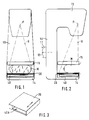
- Figure 1 shows diagrammatically in a front view a mammography apparatus which utilizes the method according to the present invention.
- Figure 2 shows the apparatus illustrated in Fig. 1 in a side view.
- Figure 3 shows an accessory-type grid assembly employed according to the invention with a construction permitting its installation on the film cassette plane.
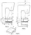
- Figure 4 shows the operation of the mammography apparatus illustrated in Fig. 2, said apparatus employing a grid assembly in accordance with the present invention, whereby said assembly is mounted so as to replace the lower compression plate of the mammography apparatus.
- Figure 5 shows the same arrangement as Fig. 4; in this case the mammography apparatus is adjusted to the "Load" position.
- Figure 6 shows an accessory-type grid assembly in accordance with the invention suitable for use in the apparatus illustrated in Figs. 4 and 5.
- Figure 7 shows in a front view the grid assembly in accordance with the invention adapted to a mammographic x-ray apparatus.
- Figure 8 shows detail D of Fig. 7 in an enlarged view.
- Figure 9 shows diagrammatically in an axonometric view the grid assembly in accordance with the present invention for use in a mammography apparatus similar to that illustrated in Figs. 7 and 8.
- Figure 10 shows in a detailed top view the an embodiment of the oscillation mechanism of the grid assembly in accordance with the present invention.
- Figure 11 shows analogously to Fig. 10 another embodiment of the oscillation mechanism of the grid assembly in accordance with the present invention.
- Figure 12 shows in a diagrammatic block diagram a control system employed for controlling a grid assembly in accordance with the present invention.
- Figure 13 shows for reference the cross section of the edge of a conventional grid assembly.
- Figure 14 shows for reference analogously to Fig. 13 the cross section of the grid assembly in accordance with the present invention.
- Figures 15A, 15B, 15C, 15D show in the travel vs. time coordinate system some advantageous paths of the oscillating motion of the grid assembly in accordance with the present invention.
- Figs. 1...6 illustrate an example of the operating environment of the invention.
- the mammography apparatus shown is comprised of a C-arm 10 carrying an x-ray tube head 13 and support arm 14 that carries fixed to it an x-ray film cassette 40 and a grid assembly 20 in accordance with the invention, both resting on said cassette.
- the grid assembly 20 contains a space 40A into which the film cassette is inserted.
- the C-arm 10 is mounted to the base (not shown) of the mammography apparatus by means of a support member 11, which allows rotation about the horizontal axis 12.
- Radiography of the breast takes place by means of an x-ray beam X emitted from the focus point F of the x-ray tube head 13 and performing the exposure of the breast onto a film 25 placed in the cassette 40, while at the same time the grid plate 22 illustrated in detail in Fig. 8 is reciprocatingly oscillated in the direction of arrow T by virtue of the method and apparatus in accordance with the present invention.
- FIGs. 4, and 6 illustrate another grid assembly in accordance with the present invention for a mammography apparatus.
- the grid assembly 20 is shaped into a tray that simultaneously acts as a lower compression plate against which an upper compression plate 15 presses the breast M to be radiographed.
- the film cassette 40 is placed onto the cassette plane 14. The mounting of the film cassette 40 is separate from the grid assembly 20 so as to allow the motion of the C-arm from a position 10 to a position 10' for bringing the film cassette 40 to its operating position.
- Figs. 7, 8 and 9 illustrate in detail the construction and operating principle of the grid assembly in accordance with the present invention.
- Fig. 8 which shows detail D of Fig. 7 in an enlarged scale, illustrates the detailed structure of the grid assembly 20 in an elevated cross-sectional view.
- the grid assembly 20 comprises a wall 21 of said assembly's supporting plane or duct, said wall being made of an x-ray transparent material, yet having appreciable stiffness so as to be capable of supporting the radiographed breast M without undergoing any essential deformation in its shape.
- the wall 21 is advantageously made of a carbon-fiber reinforced laminate, which has sufficient stiffness even for very thin walls.
- a grid plate 22 made of mutually parallel aligned lead lamellas 23 interspaced by x-ray transparent spacer members 24 of wood or plastic.
- the plane of the lamellas 23 is aligned with respect to x-ray beam X so that the lamellar grid plate 22 is transparent to x-ray radiation, while it simultaneously is capable of preventing the backscattered radiation and secondary radiation generated at the radiographed object M from reaching the x-ray film 25.
- the grid plate 22 is the upper wall 27 of the film cassette which contains the film 25 and underneath it, an image intensifier plate 26.
- the grid plates 22 are reciprocatingly oscillated according to the invention in the direction of arrow T in novel method and with a mechanism to be described later in a detailed manner.
- Fig. 10 illustrates a preferred embodiment of the apparatus based on the present invention, said apparatus having the grid plate 22 reciprocatingly oscillated in microscale amplitudes in the direction of arrow T.
- the apparatus according to Fig. 10 comprises a stepper motor 31a attached by means of-support members 32 to the base 30 of the apparatus.
- a recirculating ball screw 38 On the reversibly rotating shaft of the stepper motor 31a is mounted a recirculating ball screw 38 which carries a recirculating ball nut 39.
- the recirculating ball nut 39 is fixed to mounting lugs 35 between which a guide rail bar 34 is placed.
- the guide rail bar moves supported by bushing guide mounts 33 attached to the base member 30 of the grid assembly 20.
- a spring 36 Onto the guide rail bar 34, between a flange 37 and the second bushing guide mount 33, is adapted a spring 36.
- the grid plate 22 performs oscillations with respect to the base member 30 at microscale amplitudes.
- the purpose of the spring 36 is to remove backlash from the movements of the grid plate 22.
- the stepper motor 31a is driven by means of a control unit 50 (Fig. 12) via a driver circuit 51 so as to make the recirculating ball screw 38 to perform reciprocatingly oscillating rotations, thereby forcing the grid plate 22 to perform reciprocatingly oscillating movements at microscale amplitudes in a manner to be described later in a detail.
- Fig. 11 illustrates another embodiment of the invention analogous to that shown in Fig. 10 having, however, a different type of drive mechanism for the oscillatory rotating motion of the motor shaft with respect to that shown in Fig. 10.
- the motor 31b shown in Fig. 11 is run in one direction only.
- the shaft 40 of the motor 31b has an eccentrically slotted wheel 41 fixed to it, and a guide pin 43 fixed to a rod 44 is slidably adapted to the slot of said wheel.
- the rod 44 is attached to a mounting lug 35 of the grid plate 22.
- the slot 42 of the slotted wheel 40 is milled and shaped so that, e.g, a 45° rotation of the shaft drives the rod 44 through a full reciprocating cycle, whereby said cycle is repeated eight times per each full revolution of the slotted wheel 41.
- Fig. 12 illustrates a control unit 50 which controls the function of the motor 31 during the operation of the entire mammographic apparatus and the grid assembly 20. Attached to the control unit 50 are a keyboard 52, a display 53 and an exposure switch 54 of the mammographic apparatus. Furthermore, the control unit 50 controls the x-ray generator 13. The control unit 50 receives a signal indicating the initial position of the grid assembly 20 from a switch 56, while the information about the proper installation of the grid assembly 20 to the control unit 50 is obtained from a sensor 55.
- Figs. 13 and 14 present a comparison between the travel paths of a conventional grid assembly (Fig. 13) and a grid assembly 22 (Fig. 14) according to the present invention.
- Fig. 13 presents the guide mechanism of a prior-art grid plate 22, said mechanism comprising a guide rail 19a.
- the marginal areas of the radiographed object M are shadowed for an area P0, because the laterally shadowed width L0 of the edge of the grid 22 is in the order of approx. 10 mm, which includes the lateral motion of the grid plate 22 in the guide rail 19a and a sufficient overlapping to avoid the withdrawal of the grid plate 22 from the guide rail 19a.
- Figs. 15A...15D illustrate some preferred and typical oscillation methods for the grid plate 22 of the grid assembly 20 according to the present invention, plotted in the travel vs. time coordinate system L-t.
- the vertical axis of the coordinate system is the travel L, divided into units equal to the interlamellar distance I of the grid plate lamellas 23, while the horizontal axis is time t.
- I interlamellar distance
- I time t
- the grid plate 22 performs reciprocating oscillations in repetitive cycles T, in which the grid plate 22 moves during the time interval t0-t1 at a constant velocity, after which during the time interval t1-t2 the travel direction is reversed, and during the time interval t2-t3 again reversed, after which the grid plate 20 after reversal of its travel direction, during the time interval t3-t4, returns to its home position from where it started in the beginning of the cycle T. Consequently, according to Fig. 15A, the grid lamellas stop four times over each interlamellar space 1 at the direction change of their motion during the cycle. The stop positions are evenly distributed over the axis L of interlamellar spacings.
- Fig. 15A the motion has a maximum amplitude of 1.75 1.
- Fig. 15B illustrates a corresponding movement cycle T having four stop positions and a maximum amplitude 2.75 1 of the motion.
- Fig. 15C illustrates in greater detail the travel paths G1(t), G2(t) and G3(t) of three adjacent lamellas, these paths having their stop positions at 1/6 1, 2/6 1, 3/6 1, 4/6 1, 5/6 1 and 6/6 1 (positions K1, K2, K3, K4, K5).Consequently, the stop positions of the lamellas are evenly distributed over each interlamellar spacing, whereby the imaging of the lamellas 25 onto the film 25 is avoided.
- Fig. 15D illustrates the travel paths of three adjacent lamellas for a maximum movement amplitude of 2.83 1.
- the approach described above makes it possible to implement such an oscillation method of the lamellas 23 of the grid plate 22, which method, by virtue of the sufficiently small magnitude of the variable amplitude of the oscillating motion, achieves a satisfactorily high number of direction changes of the grid plate even within the limitations of a short length of exposure.
- the shortest exposure times can be as small as below 0.15 s.
- the stop positions of in the motion of the lamellas are critical. When these stop positions are distributed essentially evenly with a sufficient density of stop positions over the interlamellar spacings, the imaging of the grid lamellas can be avoided.
- Figs. 10 and 11 illustrate such oscillation mechanisms of the grid assembly 20 in which the motion of the grid plate 22 is altered in a cyclic and force-controlled manner so that the motion is repeated in cycles T. each of the cycles containing several changes of travel direction and stops of extremely short duration so that the total amplitude of the oscillating motion remains relatively small and typically smaller than approx. 3 1.
- the velocity of the grid plate 22 is arranged so rapid that, during the shortest practical exposures, the grid plate 22 has sufficient time for several reciprocatingly oscillating movements.
- the grid plate 22 is reciprocatingly oscillated with a constant velocity, and the direction changes of the oscillating motion are performed as abruptly and rapidly as possible.
- the oscillating motion is implemented in such a manner that the time consumed for direction changes is shorter by at least an order of magnitude with respect to the time of the linear portion of the oscillating motion.
Landscapes
- Physics & Mathematics (AREA)
- Spectroscopy & Molecular Physics (AREA)
- Engineering & Computer Science (AREA)
- General Engineering & Computer Science (AREA)
- High Energy & Nuclear Physics (AREA)
- Apparatus For Radiation Diagnosis (AREA)
- Analysing Materials By The Use Of Radiation (AREA)
- Meat, Egg Or Seafood Products (AREA)
Claims (14)
- Procédé de radiographie panoramique, ledit procédé utilisant une source de rayons X (13) dont le faisceau (X) est focalisé sur l'objet (M) à radiographier, de sorte que ledit faisceau (X) soit utilisé pour former une image de rayons X de l'objet radiographié (M) sur un film (25) ou sur un moyen de formation d'image semblable et procédé dans lequel est utilisé un ensemble de grilles (20) adapté entre l'objet radiographié (M) et le film (25) ou un moyen semblable, ledit ensemble de grilles ayant pour objet d'annuler l'effet parasite provoqué par un rayonnement rétrodiffusé ou secondaire généré dans l'objet radiographié (M) à partir de l'image radiographiée et, de plus, ledit ensemble de grilles (20) comprend une plaque de grille (22) comportant plusieurs lamelles parallèles, opaques aux rayons X et espacées essentiellement de façon équidistante, de sorte que le rayonnement X peut passer à travers des espaces (24) situés entre lesdites lamelles dans la direction du faisceau de rayons X pour agir sur le film (25) et procédé dans lequel la plaque de grille (22) est soumise à un mouvement oscillant dans le plan de la plaque de grille (22) suivant une direction T perpendiculaire à la direction longitudinale des lamelles de grille,
caractérisé en ce que la plaque de grille est soumise à un mouvement oscillant de va-et-vient d'une façon contrôlée suivant des cycles réguliers (T) de déplacement ayant une amplitude variable, de sorte que dans un cycle de retour les arrêts ou les changements de directions (K1-K5) du mouvement oscillant sont répartis de façon essentiellement régulière sur les espaces interlamellaires de la plaque de grille (22) de façon à éviter aux lamelles de grille (23) de former de façon parasite une image sur le film 25 ou un milieu semblable. - Procédé selon la revendication 1, caractérisé en ce que la plaque de grille (22) oscille suivant des cycles répétitifs (T) de déplacement, de sorte que chaque cycle (T) contient plusieurs arrêts et/ou changements de direction de déplacement.
- Procédé selon la revendication 1 ou 2, caractérisé en ce que la plaque de grille se déplace dans une direction perpendiculaire à la direction longitudinale de ses lamelles , de sorte que l'amplitude totale du mouvement est au maximum de l'ordre de 3 x 1 (1 = espacement interlamellaire des lamelles de grille) et en ce que, pour chaque cycle du déplacement, la plaque de grille (22) revient à sa position de référence après plusieurs changements de direction de déplacemets, de préférence approximativement 3...6, changements.
- Procédé selon l'une quelconque des revendications précédentes 1 à 3, caractérisé en ce que la plaque de grille (22) est soumise à un mouvement oscillant de va-et-vient ayant une vitesse essentiellement constante et en ce que les changements de direction de déplacement sont effectués dans un temps qui est plus court d'au moins un ordre de grandeur par rapport au temps utilisé pour le déplacement de la plaque de grille à vitesse constante.
- Procédé selon l'une quelconque des revendications précédentes 1 à 4, caractérisé en ce que le déplacement unidirectionnel de la plaque de grille (22) , de préférence à vitesse constante, possède une amplitude de déplacement de l'ordre de (1-2) x 1 (1 = espace interlamellaire des lamelles de grille) et en ce que la durée de la partie unidirectionnelle du déplacement se situe dans la gamme de 0,001...0,1 s, de préférence approximativement 0,01s.
- Procédé selon l'une quelconque des revendications précédentes 1 à 5, caractérisé en ce que la plaque de grille est soumise à un mouvement oscillant de va-et-vient ayant une amplitude à microéchelle telle que, même pour le temps d'exposition pratique le plus court qui se situe généralement au-dessous de 0,ls, la plaque de grille puisse faire un nombre suffisamment élevé de changements de direction de déplacement, de préférence de 3 à 10 changements pour éviter de former une image nette de la grille sur le milieu de formation d'images.
- Procédé selon l'une quelconque des revendications précédentes 1 à 6, caractérisé en ce que le procédé est appliqué à une mammographie à laquelle le sein (M) à radiographier est comprimé entre des plaques de compression (14, 15) et la plaque de grille (22) de l'ensemble de grilles (20) est placée entre le sein (M) et la cassette de film (40).
- Appareillage de radiographie , en particulier pour un usage médical, ledit appareillage comprenant une source de rayonnement X (13) dont un faisceau (X) est focalisé sur l'objet (M) à radiographier, ledit appareillage comprenant de plus une cassette de film (40) ou un dispositif de formation d'image semblable, ledit appareillage comprenant de plus un ensemble de grilles (20) composé d'une plaque de grille (22) formée d'une multitude de lamelles de grilles parallèles et/ou croisées en matériau opaque aux rayons X dont le plan est aligné parallèlement à l'axe du faisceau (X) de façon à permettre au rayonnement X de passer à travers leurs espaces interlamellaires (24) pour se focaliser sur le film (25) ou sur un milieu semblable et , finalement, ledit appareillage comprend un mécanisme de transfert grâce auquel ladite plaque de grille peut osciller le long de ses guides (19b) dans une direction perpendiculaire à l'axe longitudinal des lamelles de grille, caractérisé en ce que ledit appareillage comprend un tel mécanisme d'entrainement connecté à la plaque de grille (22) , en ce qu'il entraine la plaque de grille suivant un mouvement oscillant de va-et-vient de façon contrôlée suivant des cycles réguliers (T) de déplacement ayant une amplitude variable dans le plan de la plaque de grille de sorte que les lamelles de grille (23) sont soumises à une pluralité de changements de direction distribués de façon essentiellement régulière sur les espaces interlamellaires de la plaque de grille même au niveau des temps d'exposition les plus courts utilisés dans la formation d'images radiographiques.
- Appareillage selon la revendication 8 , caractérisé en ce que ledit appareillage comprend un moteur d'entrainement à mouvement unidirectionnel réversible (31a, 31b) qui est commandé à l'aide d'une unité de commande (50) de l'appareillage radiographique, de sorte que la plaque de grille est forcée d'effectuer un mouvement oscillant de va-et-vient dans son plan ayant une amplitude maximale de (1-3 ) x 1 ou 1 = espacement interlamellaire des lamelles de grille.
- Appareillage selon la revendication 8 ou 9, caractérisé en ce que la plaque de grille (22) est fixée à des éléments de montage (35) qui sont connectés au moteur (31a, 31b) qui communiquent à la plaque de grille (22) un mouvement oscillant de va-et-vient.
- Appareillage selon l'une quelconque des revendications précédentes 8 à 10, caractérisé en ce que ledit appareillage comprend une unité de commande (50) et un moteur (31) commandé par un circuit de commande (51) de sorte que l'arbre du moteur est entrainé pour une rotation tournant de façon unidirectionnelle ou oscillant de façon réversible et en ce que l'arbre dudit moteur (31) est connecté aux éléments de guide (34) de la plaque de grille (22) , lesdits éléments de guide permettant le déplacement de la plaque de grille (22) supportée par des montants de guidage à traversée isolée (33) fixés à la partie de base (30) de l'ensemble de grilles (20).
- Appareillage selon l'une quelconque des revendications précédentes 8 à 11, caractérisé en ce que ledit ensemble comprend un moteur pas à pas (31) entrainé par un circuit de commande (51) d'une unité de commande (50) de sorte que l'arbre du moteur est entrainé pour une rotation oscillant de façon réversible et en ce que l'arbre (38) dudit moteur pas à pas est connecté à un ensemble de guidage de la plaque de grille (22).
- Appareillage selon la revendication 12, caractérisé en ce que ledit moteur pas à pas (31) ou équivalent entraine , fixée à son arbre, une vis à circulation de billes (38) dont l'écrou à circulation de billes (39) est connecté à un ensemble de guidage (33,34,35,36) du mouvement oscillant de la plaque de grille.
- Appareillage selon l'une quelconque des revendications précédentes 8 à 13 , caractérisé en ce que ledit ensemble comprend une unité de commande (50) et un moteur (31b) connecté à un circuit de commande (51) dudit moteur , ledit moteur portant sur son arbre (40) une roue excentrique à fente (41) dont la fente (42) est connectée à un mécanisme à bielle et manivelle (43,44) qui oblige ladite plaque de grille (22) à effectuer un mouvement oscillant et en ce que ladite fente (42) de ladite roue excentrique à fente (41) est façonnée de façon à forcer la plaque de grille (22) à effectuer plusieurs oscillations ayant des ampitudes à microéchelles pendant chaque tour de ladite roue excentrique à fente (41).
Applications Claiming Priority (2)
| Application Number | Priority Date | Filing Date | Title |
|---|---|---|---|
| FI905779 | 1990-11-22 | ||
| FI905779A FI85775C (fi) | 1990-11-22 | 1990-11-22 | Foerfarande och anordning vid roentgenteknik. |
Publications (3)
| Publication Number | Publication Date |
|---|---|
| EP0487475A1 EP0487475A1 (fr) | 1992-05-27 |
| EP0487475B1 true EP0487475B1 (fr) | 1996-01-31 |
| EP0487475B2 EP0487475B2 (fr) | 2003-08-20 |
Family
ID=8531448
Family Applications (1)
| Application Number | Title | Priority Date | Filing Date |
|---|---|---|---|
| EP91850280A Expired - Lifetime EP0487475B2 (fr) | 1990-11-22 | 1991-11-13 | Méthode et appareillage pour radiographie |
Country Status (6)
| Country | Link |
|---|---|
| US (1) | US5212719A (fr) |
| EP (1) | EP0487475B2 (fr) |
| JP (1) | JPH04285541A (fr) |
| AT (1) | ATE133808T1 (fr) |
| DE (1) | DE69116816T3 (fr) |
| FI (1) | FI85775C (fr) |
Families Citing this family (22)
| Publication number | Priority date | Publication date | Assignee | Title |
|---|---|---|---|---|
| US5305369A (en) * | 1993-03-11 | 1994-04-19 | Material Control, Inc. | Bucky drive system |
| US5357554A (en) * | 1993-09-30 | 1994-10-18 | General Electric Company | Apparatus and method for reducing X-ray grid line artifacts |
| JP2822928B2 (ja) * | 1995-05-29 | 1998-11-11 | 日本電気株式会社 | Crc符号演算方法および回路 |
| US6064720A (en) * | 1997-11-26 | 2000-05-16 | Picker International, Inc. | Magnetic support for removable antiscatter grid |
| US6175117B1 (en) | 1998-01-23 | 2001-01-16 | Quanta Vision, Inc. | Tissue analysis apparatus |
| US6281503B1 (en) | 1998-05-06 | 2001-08-28 | Quanta Vision, Inc. | Non-invasive composition analysis |
| US6181773B1 (en) | 1999-03-08 | 2001-01-30 | Direct Radiography Corp. | Single-stroke radiation anti-scatter device for x-ray exposure window |
| DE19947537A1 (de) * | 1999-10-02 | 2001-04-05 | Philips Corp Intellectual Pty | Gitter zur Absorption von Röntgenstrahlung |
| US6510202B2 (en) | 2000-03-31 | 2003-01-21 | Canon Kabushiki Kaisha | Imaging apparatus, imaging method, and storage medium |
| US20040051441A1 (en) * | 2002-07-09 | 2004-03-18 | Paul Leblans | Binderless storage phosphor screen comprising a support including an amorphous (a-C) carbon layer |
| JP4753742B2 (ja) * | 2006-02-20 | 2011-08-24 | 富士フイルム株式会社 | 放射線画像撮影装置 |
| JP2008237631A (ja) * | 2007-03-28 | 2008-10-09 | Fujifilm Corp | 放射線画像撮像装置 |
| JP2010012030A (ja) * | 2008-07-03 | 2010-01-21 | Fujifilm Corp | 放射線画像撮影装置 |
| JP2010012024A (ja) * | 2008-07-03 | 2010-01-21 | Fujifilm Corp | 放射線画像撮影装置 |
| JP5361336B2 (ja) | 2008-11-06 | 2013-12-04 | キヤノン株式会社 | X線乳房撮影装置 |
| JP5238787B2 (ja) * | 2010-10-27 | 2013-07-17 | 富士フイルム株式会社 | 放射線撮影装置及び放射線撮影システム |
| USD659830S1 (en) * | 2011-01-27 | 2012-05-15 | Fujifilm Corporation | Face guard surface of mammography equipment |
| JP2014238265A (ja) * | 2011-09-30 | 2014-12-18 | 富士フイルム株式会社 | 放射線画像検出器及びその製造方法、並びに放射線画像検出器を用いた放射線撮影システム |
| JP5477982B2 (ja) * | 2012-03-30 | 2014-04-23 | 國防部軍備局中山科學研究院 | レーザ光斑絶対位置付け駆動装置と駆動システム及びその方法 |
| JP5706938B2 (ja) * | 2013-09-06 | 2015-04-22 | キヤノン株式会社 | 検出装置 |
| JP6747590B2 (ja) | 2018-03-23 | 2020-08-26 | 東レ株式会社 | 撮影台およびその製造方法、マンモグラフィ装置用撮影台およびその製造方法およびマンモグラフィ装置 |
| KR102915122B1 (ko) * | 2025-05-15 | 2026-01-20 | 제이피아이헬스케어 주식회사 | 탈부착가능한 대상체압박장치 및 대상체압박장치의 동작방법 |
Family Cites Families (13)
| Publication number | Priority date | Publication date | Assignee | Title |
|---|---|---|---|---|
| FR856752A (fr) * | 1939-03-09 | 1940-08-07 | Massiot & Cie G | Grille antidiffusante de radiographie à mouvement vibratoire |
| US2774885A (en) * | 1954-01-22 | 1956-12-18 | Howard J Brown | X-ray apparatus |
| US2938120A (en) * | 1957-12-02 | 1960-05-24 | Leslie M Forsyth | X-ray filter grid assembly and actuating means therefor |
| US3971946A (en) * | 1974-12-12 | 1976-07-27 | American Radiologic Systems Inc. | X-ray apparatus with improved housing for components |
| JPS6110293Y2 (fr) * | 1979-07-26 | 1986-04-02 | ||
| US4380086A (en) * | 1980-11-24 | 1983-04-12 | Picker Corporation | Radiation imaging system with cyclically shiftable grid assembly |
| FR2507810A1 (fr) * | 1981-06-12 | 1982-12-17 | Philips Massiot Mat Medic | Grille radiologique antidiffusante mobile, support recevant une telle grille et appareil de radiographie ainsi equipe |
| DE3316003A1 (de) * | 1983-05-03 | 1984-11-08 | Philips Patentverwaltung Gmbh, 2000 Hamburg | Vorrichtung zur beseitigung von streustrahlung |
| JPH0618571B2 (ja) * | 1985-03-26 | 1994-03-16 | 株式会社東芝 | X線撮影透視台のグリツド移動機構 |
| US4760589A (en) * | 1986-04-21 | 1988-07-26 | Siczek Aldona A | Grid cabinet and cassette tray for an X-ray examination apparatus |
| EP0255017B1 (fr) * | 1986-07-31 | 1990-06-27 | Siemens Aktiengesellschaft | Appareil de diagnostic par rayons X pour prises de vues radiographiques |
| US4901335A (en) * | 1988-11-03 | 1990-02-13 | Ferlic Daniel J | Mammography apparatus |
| US5040202A (en) * | 1989-06-05 | 1991-08-13 | General Electric | Method and apparatus for reducing x-ray grid images |
-
1990
- 1990-11-22 FI FI905779A patent/FI85775C/fi active IP Right Grant
-
1991
- 1991-11-13 DE DE69116816T patent/DE69116816T3/de not_active Expired - Fee Related
- 1991-11-13 AT AT91850280T patent/ATE133808T1/de not_active IP Right Cessation
- 1991-11-13 EP EP91850280A patent/EP0487475B2/fr not_active Expired - Lifetime
- 1991-11-15 US US07/792,726 patent/US5212719A/en not_active Expired - Lifetime
- 1991-11-22 JP JP3307682A patent/JPH04285541A/ja active Pending
Also Published As
| Publication number | Publication date |
|---|---|
| JPH04285541A (ja) | 1992-10-09 |
| FI905779A0 (fi) | 1990-11-22 |
| EP0487475A1 (fr) | 1992-05-27 |
| FI905779A7 (fi) | 1992-02-14 |
| US5212719A (en) | 1993-05-18 |
| FI85775B (fi) | 1992-02-14 |
| DE69116816T2 (de) | 1996-06-27 |
| ATE133808T1 (de) | 1996-02-15 |
| EP0487475B2 (fr) | 2003-08-20 |
| DE69116816D1 (de) | 1996-03-14 |
| DE69116816T3 (de) | 2004-04-08 |
| FI85775C (fi) | 1992-05-25 |
Similar Documents
| Publication | Publication Date | Title |
|---|---|---|
| EP0487475B1 (fr) | Méthode et appareillage pour radiographie | |
| US6181773B1 (en) | Single-stroke radiation anti-scatter device for x-ray exposure window | |
| US12023193B2 (en) | Motion compensated high throughput fast 3D radiography system with heavy duty high power multiple pulsed X-ray sources | |
| US5040202A (en) | Method and apparatus for reducing x-ray grid images | |
| US4063100A (en) | Radiographic table with movable grid assembly | |
| EP0913838B1 (fr) | Dispositif d'examen radiologique | |
| US5050199A (en) | Radiographic apparatus | |
| JP2003038482A (ja) | X線撮影装置 | |
| JP2014079518A (ja) | X線撮影装置及びモアレ画像生成方法 | |
| GB2084439A (en) | A tomographic panorama X-ray apparatus | |
| JPH07111547B2 (ja) | 運動式散乱防止グリッド用カセット | |
| JP2002000597A (ja) | X線ct装置 | |
| JP2006239164A (ja) | 放射線撮影装置 | |
| US7116758B2 (en) | Potter-bucky grid with counter-weight | |
| JPH0337050A (ja) | X線断層撮影装置 | |
| JPH10137232A (ja) | X線撮影装置 | |
| WO2009084104A1 (fr) | Equipement radiologique | |
| JPH01259843A (ja) | X線断層撮影装置 | |
| JPH0792589A (ja) | X線フィルム搬送装置 |
Legal Events
| Date | Code | Title | Description |
|---|---|---|---|
| PUAI | Public reference made under article 153(3) epc to a published international application that has entered the european phase |
Free format text: ORIGINAL CODE: 0009012 |
|
| AK | Designated contracting states |
Kind code of ref document: A1 Designated state(s): AT BE CH DE DK ES FR GB GR IT LI LU NL SE |
|
| 17P | Request for examination filed |
Effective date: 19921113 |
|
| 17Q | First examination report despatched |
Effective date: 19950419 |
|
| GRAA | (expected) grant |
Free format text: ORIGINAL CODE: 0009210 |
|
| AK | Designated contracting states |
Kind code of ref document: B1 Designated state(s): AT BE CH DE DK ES FR GB GR IT LI LU NL SE |
|
| PG25 | Lapsed in a contracting state [announced via postgrant information from national office to epo] |
Ref country code: IT Free format text: LAPSE BECAUSE OF FAILURE TO SUBMIT A TRANSLATION OF THE DESCRIPTION OR TO PAY THE FEE WITHIN THE PRE;WARNING: LAPSES OF ITALIAN PATENTS WITH EFFECTIVE DATE BEFORE 2007 MAY HAVE OCCURRED AT ANY TIME BEFORE 2007. THE CORRECT EFFECTIVE DATE MAY BE DIFFERENT FROM THE ONE RECORDED.SCRIBED TIME-LIMIT Effective date: 19960131 Ref country code: DK Effective date: 19960131 Ref country code: CH Effective date: 19960131 Ref country code: BE Effective date: 19960131 Ref country code: AT Effective date: 19960131 Ref country code: LI Effective date: 19960131 Ref country code: NL Free format text: LAPSE BECAUSE OF FAILURE TO SUBMIT A TRANSLATION OF THE DESCRIPTION OR TO PAY THE FEE WITHIN THE PRESCRIBED TIME-LIMIT Effective date: 19960131 Ref country code: FR Effective date: 19960131 Ref country code: GR Free format text: LAPSE BECAUSE OF FAILURE TO SUBMIT A TRANSLATION OF THE DESCRIPTION OR TO PAY THE FEE WITHIN THE PRESCRIBED TIME-LIMIT Effective date: 19960131 |
|
| REF | Corresponds to: |
Ref document number: 133808 Country of ref document: AT Date of ref document: 19960215 Kind code of ref document: T |
|
| REF | Corresponds to: |
Ref document number: 69116816 Country of ref document: DE Date of ref document: 19960314 |
|
| PG25 | Lapsed in a contracting state [announced via postgrant information from national office to epo] |
Ref country code: SE Effective date: 19960430 |
|
| EN | Fr: translation not filed | ||
| NLV1 | Nl: lapsed or annulled due to failure to fulfill the requirements of art. 29p and 29m of the patents act | ||
| REG | Reference to a national code |
Ref country code: CH Ref legal event code: PL |
|
| PLBI | Opposition filed |
Free format text: ORIGINAL CODE: 0009260 |
|
| PG25 | Lapsed in a contracting state [announced via postgrant information from national office to epo] |
Ref country code: GB Effective date: 19961113 |
|
| PG25 | Lapsed in a contracting state [announced via postgrant information from national office to epo] |
Ref country code: ES Free format text: THE PATENT HAS BEEN ANNULLED BY A DECISION OF A NATIONAL AUTHORITY Effective date: 19961114 |
|
| PG25 | Lapsed in a contracting state [announced via postgrant information from national office to epo] |
Ref country code: LU Free format text: LAPSE BECAUSE OF NON-PAYMENT OF DUE FEES Effective date: 19961130 |
|
| PLBF | Reply of patent proprietor to notice(s) of opposition |
Free format text: ORIGINAL CODE: EPIDOS OBSO |
|
| 26 | Opposition filed |
Opponent name: SIEMENS AG Effective date: 19961021 |
|
| PLBF | Reply of patent proprietor to notice(s) of opposition |
Free format text: ORIGINAL CODE: EPIDOS OBSO |
|
| GBPC | Gb: european patent ceased through non-payment of renewal fee |
Effective date: 19961113 |
|
| PLBO | Opposition rejected |
Free format text: ORIGINAL CODE: EPIDOS REJO |
|
| PLBO | Opposition rejected |
Free format text: ORIGINAL CODE: EPIDOS REJO |
|
| PLBO | Opposition rejected |
Free format text: ORIGINAL CODE: EPIDOS REJO |
|
| APAC | Appeal dossier modified |
Free format text: ORIGINAL CODE: EPIDOS NOAPO |
|
| APAC | Appeal dossier modified |
Free format text: ORIGINAL CODE: EPIDOS NOAPO |
|
| APAE | Appeal reference modified |
Free format text: ORIGINAL CODE: EPIDOS REFNO |
|
| APAC | Appeal dossier modified |
Free format text: ORIGINAL CODE: EPIDOS NOAPO |
|
| PLAW | Interlocutory decision in opposition |
Free format text: ORIGINAL CODE: EPIDOS IDOP |
|
| PUAH | Patent maintained in amended form |
Free format text: ORIGINAL CODE: 0009272 |
|
| STAA | Information on the status of an ep patent application or granted ep patent |
Free format text: STATUS: PATENT MAINTAINED AS AMENDED |
|
| 27A | Patent maintained in amended form |
Effective date: 20030820 |
|
| AK | Designated contracting states |
Designated state(s): AT BE CH DE DK ES FR GB GR IT LI LU NL SE |
|
| EN | Fr: translation not filed | ||
| APAH | Appeal reference modified |
Free format text: ORIGINAL CODE: EPIDOSCREFNO |
|
| PGFP | Annual fee paid to national office [announced via postgrant information from national office to epo] |
Ref country code: DE Payment date: 20081126 Year of fee payment: 18 |
|
| PG25 | Lapsed in a contracting state [announced via postgrant information from national office to epo] |
Ref country code: DE Free format text: LAPSE BECAUSE OF NON-PAYMENT OF DUE FEES Effective date: 20100601 |