EP0487946A1 - Machine centrifugeuse pour le finissage de pièces - Google Patents
Machine centrifugeuse pour le finissage de pièces Download PDFInfo
- Publication number
- EP0487946A1 EP0487946A1 EP91118834A EP91118834A EP0487946A1 EP 0487946 A1 EP0487946 A1 EP 0487946A1 EP 91118834 A EP91118834 A EP 91118834A EP 91118834 A EP91118834 A EP 91118834A EP 0487946 A1 EP0487946 A1 EP 0487946A1
- Authority
- EP
- European Patent Office
- Prior art keywords
- container
- machine according
- processing
- rotating
- liquid
- Prior art date
- Legal status (The legal status is an assumption and is not a legal conclusion. Google has not performed a legal analysis and makes no representation as to the accuracy of the status listed.)
- Granted
Links
- 230000002093 peripheral effect Effects 0.000 claims abstract description 4
- 239000007788 liquid Substances 0.000 claims description 64
- 239000000203 mixture Substances 0.000 claims description 4
- 230000000630 rising effect Effects 0.000 claims description 4
- XLYOFNOQVPJJNP-UHFFFAOYSA-N water Substances O XLYOFNOQVPJJNP-UHFFFAOYSA-N 0.000 claims description 4
- 238000004140 cleaning Methods 0.000 claims description 2
- 238000000227 grinding Methods 0.000 claims description 2
- 238000005498 polishing Methods 0.000 claims description 2
- 235000001674 Agaricus brunnescens Nutrition 0.000 claims 1
- 239000003082 abrasive agent Substances 0.000 description 6
- 238000000034 method Methods 0.000 description 2
- 239000002351 wastewater Substances 0.000 description 2
- 239000003795 chemical substances by application Substances 0.000 description 1
- 238000003754 machining Methods 0.000 description 1
- 230000010355 oscillation Effects 0.000 description 1
- 238000004064 recycling Methods 0.000 description 1
- 230000001105 regulatory effect Effects 0.000 description 1
- 238000000926 separation method Methods 0.000 description 1
- 238000004804 winding Methods 0.000 description 1
Images
Classifications
-
- B—PERFORMING OPERATIONS; TRANSPORTING
- B24—GRINDING; POLISHING
- B24B—MACHINES, DEVICES, OR PROCESSES FOR GRINDING OR POLISHING; DRESSING OR CONDITIONING OF ABRADING SURFACES; FEEDING OF GRINDING, POLISHING, OR LAPPING AGENTS
- B24B31/00—Machines or devices designed for polishing or abrading surfaces on work by means of tumbling apparatus or other apparatus in which the work and/or the abrasive material is loose; Accessories therefor
- B24B31/12—Accessories; Protective equipment or safety devices; Installations for exhaustion of dust or for sound absorption specially adapted for machines covered by group B24B31/00
-
- B—PERFORMING OPERATIONS; TRANSPORTING
- B24—GRINDING; POLISHING
- B24B—MACHINES, DEVICES, OR PROCESSES FOR GRINDING OR POLISHING; DRESSING OR CONDITIONING OF ABRADING SURFACES; FEEDING OF GRINDING, POLISHING, OR LAPPING AGENTS
- B24B31/00—Machines or devices designed for polishing or abrading surfaces on work by means of tumbling apparatus or other apparatus in which the work and/or the abrasive material is loose; Accessories therefor
- B24B31/10—Machines or devices designed for polishing or abrading surfaces on work by means of tumbling apparatus or other apparatus in which the work and/or the abrasive material is loose; Accessories therefor involving other means for tumbling of work
- B24B31/108—Machines or devices designed for polishing or abrading surfaces on work by means of tumbling apparatus or other apparatus in which the work and/or the abrasive material is loose; Accessories therefor involving other means for tumbling of work involving a sectioned bowl, one part of which, e.g. its wall, is stationary and the other part of which is moved, e.g. rotated
Definitions
- the invention relates to a centrifugal machine for mechanical processing, e.g. Grinding, polishing, cleaning and deburring, of workpieces in a processing container, which has a fixed and essentially cylindrical casing during operation and a coaxial bearing, rotating base during processing in the form of a plate or the like. has, which protrudes with its peripheral edge to form a gap on the cylindrical jacket.
- the container is emptied from the workpieces, possibly abrasives after they have been finished and possibly from the abrasives used, through a closable opening in the side wall of the container shell, through which the workpieces continue to rotate as the Container bottom are thereby thrown out of the processing container under centrifugal force acting on them (DE-A-31 42 868). Since the workpieces come into contact with a relatively high centrifugal force on a wall of the intended collecting space, there is a risk of damage, particularly to sensitive workpieces.
- centrifugal force processing process is mostly a wet process, which requires the supply and discharge of liquid (water-compound mixture) and abrasives (chips), there must be supply and discharge lines that take into account the cable connections for drive and control of the swivel angle must also be moved.
- the invention has for its object to design a centrifugal processing machine of the type mentioned in such a way that the workpieces machined in its processing container can be gently removed without swiveling the container.
- the rotating container bottom has at least one opening dimensioned for the workpiece removal from the processing container, which can be closed by a rotating cover, and in that a trough under the bottom opening for collecting the workpieces and, if necessary, the same the processing tank emerging processing agents (liquid and abrasives).
- the workpieces can be removed in a gentle manner, even when the bottom of the container is shut down or at a low speed and with a low drop height, for which purpose it is not necessary to pivot the processing container about a horizontal axis.
- closure body for this opening can be formed by a liftable and lowerable, mushroom-shaped or umbrella-shaped closure body which can be pushed into the emptying opening from below, the mounting of the closure body which allows the movement up and down to be provided below or above the container bottom.
- the rotating container base is rotatably supported by a bearing ring on a machine frame which extends around this opening below the emptying opening.
- This decentralized storage leads to a high positional stability of the rotating container base during its rotation, which is particularly good if the bearing ring has an outside diameter that comes as close as possible to the outside diameter of the rotating container base. As a result, a constant, smallest possible gap width can be obtained over the entire circumference of the floor without oscillation or knocking occurring.
- the processing liquid flowing out of the processing container through the gap can be collected by a liquid container located under the container.
- the aforementioned liquid container which surrounds the processing container, is firmly connected to the rotating base thereof and can be rotated with it about the bottom rotation axis.
- this liquid container is provided below the rotating bottom of the processing container with at least one opening for the passage of the workpieces and processing means to be removed therefrom, which opening can also be closed by a rotating closure body.
- This closure body can be the same as that for closing the opening in the bottom of the processing container.
- the bearing for the rotatable bottom of the processing container and the liquid container rotating therewith can be arranged in such a way that it does not come into contact with the processing liquid running off (dirty water), so that it does not have wearing seals to protect the bearings got to.
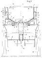
- an outer wall 2 rests on a machine frame 1, on the upper edge of which the fixed and essentially cylindrical casing 3 of the processing container 4 is supported or supported.
- the bottom 6 of the processing container which is coaxial with the jacket and can be set in rotation, projects to the lower edge of this jacket 3 and has the shape of a plate.
- the processing container 4 is surrounded by a liquid container 7, which is firmly connected in its base region to the rotating base 6 of the processing container and can be rotated about the axis of rotation X thereof.
- This liquid container has on its underside a bearing ring 9 provided with a ball bearing 8, by means of which the liquid container 7 with the rotating base 6 is rotatably mounted on the machine frame 1.
- a drive ring 10 is also provided on the underside of the liquid container, via which a drive belt 11 runs, which can be put into circulation by the pulley of an electric motor 12.
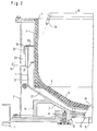
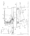
- Both the rotating base 6 of the processing container 4 and the liquid container 7 firmly connected to it each have a central opening 13 and 14 (Fig. 2/3) which are arranged one below the other coaxially to the axis of rotation X of the container base 6.
- These two openings can be closed together by a mushroom-shaped closure body 15, which sits on a lifting and lowering rod 16, which is mechanically or pneumatically raised and lowered in a guide 17.
- This lifting and lowering rod 16 extends through a below the bottom of the liquid container 7 and its storage 8, 9 arranged guide 17, which is attached to the fixed frame and a collecting tray 18 arranged under this guide with a funnel 28 above it, which collecting tray as Vibrating channel with sieve bottom 19 is formed.
- This collecting trough is mounted on stands 20 via oscillating cushions 21 and is set in vibration by an oscillating drive 22.
- this collecting trough 18 is broken, the lifting and lowering rod being shielded from the interior of the trough 18 by a jacket tube 23 which extends at a distance around the lifting and lowering rod and at the bottom of the Tub 18 is attached.
- this jacket tube 23 projects into a cylindrical collar 24 which is fastened to the underside of the closure body 15 and can be designed to be axially foldable.
- a feed line 25 with an outlet nozzle 26 is used to supply the processing liquid (water-compound mixture).
- the liquid introduced into the container 4 is distributed in the interior of the container and gradually flows through the gap 5 into the space 27 between the processing container 4 and the liquid container one that guides the liquid and is therefore referred to as the liquid space.
- the height regulation of the liquid level in the processing container 4 can be determined via the quantity of the liquid supplied through the feed line 25 and by regulating the quantity of liquid emerging from the liquid container by centrifugal force.
- a ring is located above the rings 31 the jacket 3 of the processing container 4 is provided with a web 29 extending around it, which is height-adjustable on the jacket and extends with its outer edge over the angular wall 32 forming the water overflow.
- a gap 30 is formed between this web 29 and the water overflow, the width of which can be adjusted, as a result of which the amount of liquid flowing out of the liquid container 7 via the overflow can be adjusted.
- the height adjustment of the web 29 on the jacket 3 can be such that the gap 30 can be reduced to practically zero if no or no significant amount of liquid is to flow out of the liquid container.
- the side wall of the co-rotating liquid container 7 may be expedient not to arrange the side wall of the co-rotating liquid container 7 vertically, as in the illustrated embodiment, but to incline it inwards or outwards, as a result of which the rising of the liquid on this side wall can be hindered or reinforced .
- the container base 6 rotates with the liquid container 7, the mushroom-shaped closure body 15 closing the openings 13 and 14 in the rotating base 6 and in the rotating liquid container 7 by means of its lifting and lowering rod 16.
- this closure body 15 lies with its conical side face close to the end edges of the openings 13, 14, which are aligned parallel to this, in the two rotating machine parts mentioned.
- the closure body can be closed over or over when the bottom 6 of the container is stationary or rotating only slowly
- Lifting and lowering rod 16 in the drawings can be moved downwards continuously from the aforementioned openings into its open position shown in dashed lines in FIGS. 1 and 3, as a result of which the two openings 13 and 14 are exposed.
- Fig. 2 shows the beginning of the opening movement.
- the liquid in the processing container 4 and in the liquid container 7 flows together with the workpieces in the processing container and possibly abrasives through these openings through the closure body 15 into the collecting trough 18 designed as a vibrating conveyor trough, from which the liquid flows out via the sieve plate 19. while the dewatered workpieces and possibly abrasives are removed via the vibrating conveyor trough for further use or separation.
- the liquid is either discharged via a drain line 35 to the wastewater or for its further use via appropriate recirculation tanks and filter devices or fed to recycling treatment plants.
- the drop height of the workpieces can be controlled into the collecting trough, whereby damage to the workpieces when they are removed from the processing container can be avoided.
- the processing container 4 can be rinsed via the liquid feed line 25.
- the bottom emptying of the processing container according to the invention has the advantage that, in relation to the container volume, there is a relatively low drop height of the workpieces and processing means, such as water-compound mixture and abrasive, which minimizes the risk of damage to the workpieces when they emerge from the processing container. Since the processing container does not have to be swiveled to empty it, the liquid flow in the container can be such that dry working is guaranteed.
Landscapes
- Engineering & Computer Science (AREA)
- Mechanical Engineering (AREA)
- Centrifugal Separators (AREA)
- Gripping On Spindles (AREA)
- Finish Polishing, Edge Sharpening, And Grinding By Specific Grinding Devices (AREA)
Applications Claiming Priority (2)
| Application Number | Priority Date | Filing Date | Title |
|---|---|---|---|
| DE4038253A DE4038253A1 (de) | 1990-11-30 | 1990-11-30 | Fliehkraftbearbeitungsmaschine |
| DE4038253 | 1990-11-30 |
Publications (2)
| Publication Number | Publication Date |
|---|---|
| EP0487946A1 true EP0487946A1 (fr) | 1992-06-03 |
| EP0487946B1 EP0487946B1 (fr) | 1995-03-01 |
Family
ID=6419310
Family Applications (1)
| Application Number | Title | Priority Date | Filing Date |
|---|---|---|---|
| EP91118834A Expired - Lifetime EP0487946B1 (fr) | 1990-11-30 | 1991-11-05 | Machine centrifugeuse pour le finissage de pièces |
Country Status (4)
| Country | Link |
|---|---|
| US (1) | US5211673A (fr) |
| EP (1) | EP0487946B1 (fr) |
| DE (2) | DE4038253A1 (fr) |
| ES (1) | ES2069800T3 (fr) |
Cited By (1)
| Publication number | Priority date | Publication date | Assignee | Title |
|---|---|---|---|---|
| EP0649705A1 (fr) * | 1993-10-22 | 1995-04-26 | Sintobrator, Ltd. | Machine vibrante d'abrasion à sec |
Families Citing this family (9)
| Publication number | Priority date | Publication date | Assignee | Title |
|---|---|---|---|---|
| JP2913473B2 (ja) * | 1997-01-31 | 1999-06-28 | 株式会社チップトン | 間隙調整機能を有する渦流バレル加工機及び退避層成形方法並びに間隙調整方法 |
| DE29702859U1 (de) * | 1997-02-19 | 1998-03-19 | Gegenheimer, Helmut, 75210 Keltern | Fliehkraft-Gleitschleifmaschine |
| JP3502839B2 (ja) * | 2001-02-20 | 2004-03-02 | 株式会社チップトン | 遠心バレル研磨装置 |
| US7871307B2 (en) * | 2005-02-15 | 2011-01-18 | Sintokogio, Ltd. | Fluid barrel-polishing device and polishing method |
| CN102218697B (zh) | 2010-04-19 | 2014-02-26 | 国际商业机器公司 | 高速滚筒研磨抛光设备 |
| JP5904403B2 (ja) * | 2012-02-16 | 2016-04-13 | 新東工業株式会社 | 流動式バレル研磨装置 |
| DE102012025233B4 (de) * | 2012-12-28 | 2016-06-09 | Otec Präzisionsfinish GmbH | Schlepp- und/oder Tauchfinishmaschine zur Oberflächenbearbeitung von Werkstücken mittels Schleif- und/oder Poliergranulat in Gegenwart eines flüssigen Bearbeitungsmediums |
| WO2017030979A1 (fr) * | 2015-08-14 | 2017-02-23 | The Texas A&M University System | Procédé et appareil de réalisation de polissage ciblé par la manipulation de fluide abrasif magnétique |
| CN111266989B (zh) * | 2020-02-28 | 2021-02-09 | 太仓市凯福士机械有限公司 | 金属工件除油光饰一体桶 |
Citations (5)
| Publication number | Priority date | Publication date | Assignee | Title |
|---|---|---|---|---|
| CH455555A (de) * | 1967-09-09 | 1968-07-15 | Meier Kurt | Verfahren zum Waschen, Scheuern, Entgraten, Polieren oder Mischen von Bearbeitungsgut sowie Vorrichtung zur Ausübung des Verfahrens |
| DE2516721B1 (de) * | 1975-04-16 | 1976-05-26 | Messer Griesheim Gmbh | Vorrichtung zum Entgraten von Werkstuecken aus Gummi oder aehnlichen kaelteversproedbaren Werkstoffen |
| EP0088237A2 (fr) * | 1982-03-06 | 1983-09-14 | Carl Kurt Walther GmbH & Co. KG | Récipient vibrant pour la floculation des eaux résiduelles obtenues par le traitement "au tonneau" |
| EP0205161A2 (fr) * | 1985-06-11 | 1986-12-17 | Rösler Gleitschlifftechnik Maschinenbau und Technische Keramik GmbH | Machine de polissage à centrifugation |
| CH659969A5 (en) * | 1983-05-19 | 1987-03-13 | Ernst A Huber | Emptying device |
Family Cites Families (10)
| Publication number | Priority date | Publication date | Assignee | Title |
|---|---|---|---|---|
| SU831570A1 (ru) * | 1979-01-04 | 1981-05-23 | Уфимский Ордена "Знак Почета" Приборо-Строительный Завод Им.B.И.Ленина | Устройство дл обработки деталей |
| US4408417A (en) * | 1980-10-31 | 1983-10-11 | Shikishima Tipton Mfg. Co., Ltd. | Fully automatic barrel finishing machine |
| JPS5924957A (ja) * | 1982-07-30 | 1984-02-08 | Toyota Motor Corp | バレル加工装置 |
| JPS5924955A (ja) * | 1982-07-30 | 1984-02-08 | Toyota Motor Corp | バレル装置 |
| JPS5953157A (ja) * | 1982-09-17 | 1984-03-27 | Tipton Mfg Corp | 遊星旋回式バレル加工機 |
| DE3604619A1 (de) * | 1986-02-14 | 1987-08-20 | Spaleck Gmbh Max | Fliehkraftbearbeitungsmaschine |
| US4884372A (en) * | 1987-10-06 | 1989-12-05 | Roto-Finish Company, Inc. | Centrifugal finishing apparatus embodying improved seal and method |
| DE3802542C1 (fr) * | 1988-01-28 | 1989-08-24 | Max Spaleck Gmbh & Co Kg, 4290 Bocholt, De | |
| US5088238A (en) * | 1991-02-20 | 1992-02-18 | Lin Chao Tong | Polishing grinder with turbulent flow of grinding solution for grinding |
| US5046287A (en) * | 1991-02-20 | 1991-09-10 | Lin Chao Tong | Wet grinding type of grinder with improved material discharge mechanism |
-
1990
- 1990-11-30 DE DE4038253A patent/DE4038253A1/de not_active Withdrawn
-
1991
- 1991-11-05 EP EP91118834A patent/EP0487946B1/fr not_active Expired - Lifetime
- 1991-11-05 ES ES91118834T patent/ES2069800T3/es not_active Expired - Lifetime
- 1991-11-05 DE DE59104779T patent/DE59104779D1/de not_active Expired - Fee Related
- 1991-11-19 US US07/794,402 patent/US5211673A/en not_active Expired - Fee Related
Patent Citations (5)
| Publication number | Priority date | Publication date | Assignee | Title |
|---|---|---|---|---|
| CH455555A (de) * | 1967-09-09 | 1968-07-15 | Meier Kurt | Verfahren zum Waschen, Scheuern, Entgraten, Polieren oder Mischen von Bearbeitungsgut sowie Vorrichtung zur Ausübung des Verfahrens |
| DE2516721B1 (de) * | 1975-04-16 | 1976-05-26 | Messer Griesheim Gmbh | Vorrichtung zum Entgraten von Werkstuecken aus Gummi oder aehnlichen kaelteversproedbaren Werkstoffen |
| EP0088237A2 (fr) * | 1982-03-06 | 1983-09-14 | Carl Kurt Walther GmbH & Co. KG | Récipient vibrant pour la floculation des eaux résiduelles obtenues par le traitement "au tonneau" |
| CH659969A5 (en) * | 1983-05-19 | 1987-03-13 | Ernst A Huber | Emptying device |
| EP0205161A2 (fr) * | 1985-06-11 | 1986-12-17 | Rösler Gleitschlifftechnik Maschinenbau und Technische Keramik GmbH | Machine de polissage à centrifugation |
Cited By (1)
| Publication number | Priority date | Publication date | Assignee | Title |
|---|---|---|---|---|
| EP0649705A1 (fr) * | 1993-10-22 | 1995-04-26 | Sintobrator, Ltd. | Machine vibrante d'abrasion à sec |
Also Published As
| Publication number | Publication date |
|---|---|
| ES2069800T3 (es) | 1995-05-16 |
| DE4038253A1 (de) | 1992-06-04 |
| DE59104779D1 (de) | 1995-04-06 |
| EP0487946B1 (fr) | 1995-03-01 |
| US5211673A (en) | 1993-05-18 |
Similar Documents
| Publication | Publication Date | Title |
|---|---|---|
| EP0799643B1 (fr) | Dispositif de traitement de suspensions | |
| EP0173271B1 (fr) | Broyeur à billes à passage annulaire | |
| DE3604619A1 (de) | Fliehkraftbearbeitungsmaschine | |
| AT398706B (de) | Verfahren und vorrichtung zur filtration | |
| EP0487946B1 (fr) | Machine centrifugeuse pour le finissage de pièces | |
| DE1652151A1 (de) | Verfahren und Vorrichtung zur Oberflaechenbehandlung von Werkstuecken | |
| DE3142868A1 (de) | Fliehkraftbearbeitungsmaschine | |
| DE1611060A1 (de) | Verfahren und Anlage zur Behandlung sowohl Fluessigkeiten als auch Feststoffe enthaltender Materialien | |
| EP1194383A1 (fr) | Dispositif de deshydratation des boues | |
| DE915408C (de) | Verfahren zum Betrieb einer Muehle | |
| DE3223689C1 (de) | Verfahren und Vorrichtung zur Gewinnung von Metallteilen aus Verbrennungs- und/oder Pyrolyse-Rückständen, insbesondere aus der Müllverbrennung | |
| DE60014523T2 (de) | Dispersionsvorrichtung für Materialien | |
| EP0571394B1 (fr) | Dispositif de degraissage pour pieces de serie | |
| DE2742415A1 (de) | Verfahren und vorrichtung zum herstellen der feuerfesten zustellung metallurgischer gefaesse | |
| DE69602740T2 (de) | Systeme zum entfernen von flüssigkeiten aus tanks | |
| DE3939426C2 (de) | Vorrichtung zum Abtrennen von Feststoffen aus einer Flüssigkeit oder zum Abtrennen von aus Emulsionen ausgefällten Sedimenten | |
| DE1298081B (de) | Austragsvorrichtung fuer ein Nutschfilter | |
| DE3029684A1 (de) | Kombinierter misch- und filtrationsapparat | |
| DE19822191C1 (de) | Diskontinuierliche Zentrifuge mit einer Ausräumeinrichtung | |
| DE2609661A1 (de) | Mahlvorrichtung zum zerkleinern von insbesondere koernigem gut | |
| DE2409224C3 (de) | Vorrichtung zum Klassieren von festen Bestandteilen einer flüssigen Mischung | |
| DE931551C (de) | Vorrichtung zum Aufbereiten von Futtermitteln, insbesondere Roh- und Gruenfutter | |
| EP0070352A2 (fr) | Dispositif pour le découpage en morceaux | |
| EP0628348A2 (fr) | Dispositif de régulation de la zone d'admission d'un broyeur vertical | |
| DE2416977A1 (de) | Verfahren und einrichtung zum aufstampfen von pfannenfuttern |
Legal Events
| Date | Code | Title | Description |
|---|---|---|---|
| PUAI | Public reference made under article 153(3) epc to a published international application that has entered the european phase |
Free format text: ORIGINAL CODE: 0009012 |
|
| AK | Designated contracting states |
Kind code of ref document: A1 Designated state(s): CH DE ES FR GB IT LI |
|
| 17P | Request for examination filed |
Effective date: 19920826 |
|
| 17Q | First examination report despatched |
Effective date: 19921211 |
|
| GRAA | (expected) grant |
Free format text: ORIGINAL CODE: 0009210 |
|
| AK | Designated contracting states |
Kind code of ref document: B1 Designated state(s): CH DE ES FR GB IT LI |
|
| GBT | Gb: translation of ep patent filed (gb section 77(6)(a)/1977) |
Effective date: 19950224 |
|
| ET | Fr: translation filed | ||
| REF | Corresponds to: |
Ref document number: 59104779 Country of ref document: DE Date of ref document: 19950406 |
|
| REG | Reference to a national code |
Ref country code: ES Ref legal event code: FG2A Ref document number: 2069800 Country of ref document: ES Kind code of ref document: T3 |
|
| ITF | It: translation for a ep patent filed | ||
| PGFP | Annual fee paid to national office [announced via postgrant information from national office to epo] |
Ref country code: ES Payment date: 19950927 Year of fee payment: 5 |
|
| PGFP | Annual fee paid to national office [announced via postgrant information from national office to epo] |
Ref country code: GB Payment date: 19951009 Year of fee payment: 5 |
|
| PGFP | Annual fee paid to national office [announced via postgrant information from national office to epo] |
Ref country code: FR Payment date: 19951122 Year of fee payment: 5 |
|
| PGFP | Annual fee paid to national office [announced via postgrant information from national office to epo] |
Ref country code: CH Payment date: 19951128 Year of fee payment: 5 |
|
| PGFP | Annual fee paid to national office [announced via postgrant information from national office to epo] |
Ref country code: DE Payment date: 19951130 Year of fee payment: 5 |
|
| PLBE | No opposition filed within time limit |
Free format text: ORIGINAL CODE: 0009261 |
|
| STAA | Information on the status of an ep patent application or granted ep patent |
Free format text: STATUS: NO OPPOSITION FILED WITHIN TIME LIMIT |
|
| 26N | No opposition filed | ||
| PG25 | Lapsed in a contracting state [announced via postgrant information from national office to epo] |
Ref country code: GB Effective date: 19961105 |
|
| PG25 | Lapsed in a contracting state [announced via postgrant information from national office to epo] |
Ref country code: ES Free format text: LAPSE BECAUSE OF THE APPLICANT RENOUNCES Effective date: 19961106 |
|
| PG25 | Lapsed in a contracting state [announced via postgrant information from national office to epo] |
Ref country code: LI Effective date: 19961130 Ref country code: CH Effective date: 19961130 |
|
| GBPC | Gb: european patent ceased through non-payment of renewal fee |
Effective date: 19961105 |
|
| REG | Reference to a national code |
Ref country code: CH Ref legal event code: PL |
|
| PG25 | Lapsed in a contracting state [announced via postgrant information from national office to epo] |
Ref country code: FR Effective date: 19970731 |
|
| PG25 | Lapsed in a contracting state [announced via postgrant information from national office to epo] |
Ref country code: DE Effective date: 19970801 |
|
| REG | Reference to a national code |
Ref country code: FR Ref legal event code: ST |
|
| REG | Reference to a national code |
Ref country code: ES Ref legal event code: FD2A Effective date: 20010402 |
|
| PG25 | Lapsed in a contracting state [announced via postgrant information from national office to epo] |
Ref country code: IT Free format text: LAPSE BECAUSE OF NON-PAYMENT OF DUE FEES;WARNING: LAPSES OF ITALIAN PATENTS WITH EFFECTIVE DATE BEFORE 2007 MAY HAVE OCCURRED AT ANY TIME BEFORE 2007. THE CORRECT EFFECTIVE DATE MAY BE DIFFERENT FROM THE ONE RECORDED. Effective date: 20051105 |