EP0487977B1 - Système de chasse automatique d'une cuvette de W.C. - Google Patents
Système de chasse automatique d'une cuvette de W.C. Download PDFInfo
- Publication number
- EP0487977B1 EP0487977B1 EP91119374A EP91119374A EP0487977B1 EP 0487977 B1 EP0487977 B1 EP 0487977B1 EP 91119374 A EP91119374 A EP 91119374A EP 91119374 A EP91119374 A EP 91119374A EP 0487977 B1 EP0487977 B1 EP 0487977B1
- Authority
- EP
- European Patent Office
- Prior art keywords
- sensor
- flushing
- user
- water
- flushing system
- Prior art date
- Legal status (The legal status is an assumption and is not a legal conclusion. Google has not performed a legal analysis and makes no representation as to the accuracy of the status listed.)
- Expired - Lifetime
Links
- 238000011010 flushing procedure Methods 0.000 title claims description 58
- 238000001514 detection method Methods 0.000 claims description 19
- 230000013872 defecation Effects 0.000 claims description 18
- XLYOFNOQVPJJNP-UHFFFAOYSA-N water Substances O XLYOFNOQVPJJNP-UHFFFAOYSA-N 0.000 description 9
- 238000004140 cleaning Methods 0.000 description 4
- 238000010586 diagram Methods 0.000 description 3
- 238000013459 approach Methods 0.000 description 2
- 230000027939 micturition Effects 0.000 description 2
- 230000001681 protective effect Effects 0.000 description 2
- 230000000694 effects Effects 0.000 description 1
- 210000003608 fece Anatomy 0.000 description 1
- 230000003287 optical effect Effects 0.000 description 1
Images


Classifications
-
- E—FIXED CONSTRUCTIONS
- E03—WATER SUPPLY; SEWERAGE
- E03D—WATER-CLOSETS OR URINALS WITH FLUSHING DEVICES; FLUSHING VALVES THEREFOR
- E03D5/00—Special constructions of flushing devices, e.g. closed flushing system
- E03D5/10—Special constructions of flushing devices, e.g. closed flushing system operated electrically, e.g. by a photo-cell; also combined with devices for opening or closing shutters in the bowl outlet and/or with devices for raising/or lowering seat and cover and/or for swiveling the bowl
- E03D5/105—Special constructions of flushing devices, e.g. closed flushing system operated electrically, e.g. by a photo-cell; also combined with devices for opening or closing shutters in the bowl outlet and/or with devices for raising/or lowering seat and cover and/or for swiveling the bowl touchless, e.g. using sensors
-
- Y—GENERAL TAGGING OF NEW TECHNOLOGICAL DEVELOPMENTS; GENERAL TAGGING OF CROSS-SECTIONAL TECHNOLOGIES SPANNING OVER SEVERAL SECTIONS OF THE IPC; TECHNICAL SUBJECTS COVERED BY FORMER USPC CROSS-REFERENCE ART COLLECTIONS [XRACs] AND DIGESTS
- Y10—TECHNICAL SUBJECTS COVERED BY FORMER USPC
- Y10S—TECHNICAL SUBJECTS COVERED BY FORMER USPC CROSS-REFERENCE ART COLLECTIONS [XRACs] AND DIGESTS
- Y10S4/00—Baths, closets, sinks, and spittoons
- Y10S4/03—Electric flushing
Definitions
- the present invention relates to a water-closet bowl automatic-flushing system which detects the state where a user sits on a closet seat for defecation and operates in association with the user standing up to leave.
- a forced flushing sensor is provided in order to flow water under intention of the user.
- AU-B-590,492 describes a flushing system comprising sensor means to detect the presence of a user. However, only the use of this systems for a urinal is described.
- US-A-4 570 272 discloses a toilet bowl flushing device which comprises means of detecting approach and departure of users of the bowl. The operation of the system follows a specific timing chart. Means allowing the user or someone cleaning the toilet to actuate or stop the flushing device are not described.
- a water-closet bowl automatic-flushing system of the present invention disposes a defecating position detection sensor at the rear of the toilet so as to project light to the back of the user.
- the water-closet bowl automatic-flushing system of the present invention is so constructed that, when the user sits on the closet seat prior to defecation, preliminary flushing is carried out and the interior of the closet bowl is wetted with water so as to make it easy to wash out faeces by full water flush.
- the preliminary water-flushing mechanism comprises a photosensor controllable in non-contact without operating a lever or a handle.
- a pipe-line covering stand 13 in which water-flushing pipes 16 are housed.
- a bowl 1 is disposed at the center of the toilet room and a closet seat 2 is mounted on the bowl 1, the closet seat 2 being upwardly rotatable for use by men for urination.
- a sensor cover 8 At the center of a decorative cover 7 is disposed a sensor cover 8 and an electronic box 15 is attached to the rear surface of the decorative cover 7.
- a sensor mounting plate 9 On the upper surface of the electronic box 15, as shown in Fig. 5, is provided a sensor mounting plate 9, to which a forced water-flushing sensor and a defecating position detection sensor or, for example, an optical system are fixed.
- a forced water-flush sensor projector 5 and a forced water-flush sensor photodetector 6 constituting the forced water-flush sensor are disposed side by side a forced water-flush sensor projector 5 and a forced water-flush sensor photodetector 6 constituting the forced water-flush sensor.
- a defecating position detection sensor photodetector 3 At the lower portion of the same is disposed a defecating position detection sensor photodetector 3 and at the lowermost portion of the same is disposed a defecating position detection sensor projector 4.
- a human body detection display lamp 14 Between the evacuation position detection sensor photodetector 3 and the defecating position detection sensor projector 4 are disposed a human body detection display lamp 14, a remote control photodetector 10, and a remote control stop display lamp 11.
- a remote control operation device which serves to stop the bowl automatic-flushing system in order not to flow water in vain each time a cleaner approaches the bowl 1 for cleaning the toilet room.
- the bowl automatic-flushing system is reset and the remote control display lamp 11 is switched off, thereby starting the automatic-flushing system.
- the forced flushing sensor photodetector 6 detects the infrared ray to flush the bowl with water.
- the forced flushing sensor projector 5 and the forced flushing sensor photodetector 6 constituting the forced flushing sensor, as shown in Fig. 5, are made small in sensor length c thereof, as shown in Fig. 2, and there is an elongate slot open at the center of the closet seat 2, so that, when a male opens the closet seat 2 to urinate, the forced flushing sensor does not operate.
- the male after the end of urination, enters his hands into the length c of forced flushing sensor to intercept the infrared ray so as to thereby flow water.
- the sensor length of the infrared ray from the defecating position detection sensor is adapted to be switched into either a defecation state sensor length b or an end state sensor length a.
- the defecating position detection sensor When the toilet room is empty, in other words, at the time when the former user gets out therefrom, the defecating position detection sensor has been switched to be of the defecation state sensor length b.
- the defecating position detection sensor is switched to the end state sensor length a, and then decides whether or not the user gets out from the end state sensor length a, thereby turning on the defecation finish switch.
- the defecating position detection sensor is switched into the end state sensor length a and defecation state sensor length b by changing a response difference of the infrared ray sensor, but two separate infrared ray sensors are not provided.
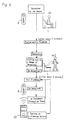
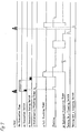
- Fig. 6 is a block diagram for control of the bowl automatic-flushing system of the present invention and Fig. 7 is a time chart thereof.
- a user enters into the toilet room, at which time the defecating position detection sensor has been switched to be of the defecation state sensor length b, the length b being about 450 mm, so that in the state where he enters into a first position M1 and sits on the closet seat 2, the defecating position detection sensor detects the above so as to turn on the defecation switch, and when the time of turning on the defecating switch due to the defecation state sensor length b continues for about three seconds, the preliminary flushing timer is on, thereby preliminarily flowing water for flushing the bowl 1.
- the defecating position detection sensor When the user enters into the defecation state sensor length b and the defecation switch is on, the defecating position detection sensor has been switched to the end state sensor length a.
- the defecating position sensor turns on the defecation end switch, so that, when the state where the defecation switch is on continues for about t2 seconds (about five seconds), the full flushing timer is turned on. Then, more water than during the preliminary flushing is flowed to perform the full flushing.
- a forced flushing sensor separate from the defecating position sensor is provided, so that the user intercepts the infrared ray by his hands and the forced flushing sensor is turned on to perform the forced flushing.
- an equipment protective timer is provided.
- flushing is arranged to be carried out once every 24 hours in order to protect the bowl automatic-flushing system.
- the equipment protective timer starts the time counting from the time point of finishing the full flushing so that, when the remote control operation device 20 turns on the flushing switch, the time counting is intermitted.
- the full flushing timer is on so as to perform full flushing.
- the present invention has the following effect.
- the first position M1 where the evacuation switch is on is shifted from the second position M2 where the defecation finish switch is on, so as to give hysteresis, whereby unstable control generated when both the positions are coincident with each other can be eliminated.
- the forced flushing sensor is provided which operates by intercepting the infrared ray by the user's hands.
- the user intends to carry out particular flushing, he can carry out water flushing at any time.
- the forced flushing sensor is part of the decorative cover 7 at the rear of the toilet and disposed in proximity to the defecating position detection sensor, whereby parts with reference to the electronic circuit can integrally be disposed.
Landscapes
- Engineering & Computer Science (AREA)
- Aviation & Aerospace Engineering (AREA)
- Health & Medical Sciences (AREA)
- Life Sciences & Earth Sciences (AREA)
- Hydrology & Water Resources (AREA)
- Public Health (AREA)
- Water Supply & Treatment (AREA)
- Sanitary Device For Flush Toilet (AREA)
- Bidet-Like Cleaning Device And Other Flush Toilet Accessories (AREA)
- Toilet Supplies (AREA)
Claims (4)
- Système de chasse automatique de cuvette de W-C, comprenant un capteur (3, 4) de position de défécation placé à l'arrière des W-C (1), ledit capteur délivrant un signal de chasse préliminaire lorsqu'un utilisateur s'assoie dans une première position (M1) et un signal de chasse complète lorsque l'utilisateur après défécation prend une seconde position (M2), caractérisé en ce que le champ du capteur de détection de position de défécation est commuté d'un champ b de capteur en champ a de capteur plus long lorsque l'utilisateur s'assoie dans ladite première position (M1) et est commuté de nouveau en un champ b de capteur plus court lorsque l'utilisateur prend ladite seconde position (M2).
- Système de chasse automatique de cuvette de W-C selon la revendication 1, caractérisé en ce que ledit champ b de capteur est d'environ 450 mm et ledit champ a de capteur est d'environ 950 mm.
- Système de chasse automatique de cuvette de W-C selon la revendication 1 ou 2, caractérisé en ce qu'en outre un capteur (5, 6) de chasse complète qui peut être commandé par l'utilisateur est placé à proximité dudit capteur (3, 4) de détection de position de défécation.
- Système de chasse automatique de cuvette de W-C selon une quelconque des revendications précédentes, caractérisé en ce qu'il comprend en outre un photodétecteur (10) de commande à distance pour mettre hors-fonction le système.
Applications Claiming Priority (4)
| Application Number | Priority Date | Filing Date | Title |
|---|---|---|---|
| JP334370/90 | 1990-11-29 | ||
| JP33436990A JPH04202923A (ja) | 1990-11-29 | 1990-11-29 | 大便器自動洗浄システム |
| JP334369/90 | 1990-11-29 | ||
| JP33437090A JPH04202924A (ja) | 1990-11-29 | 1990-11-29 | 大便器自動洗浄システムの強制洗浄センサー |
Publications (2)
| Publication Number | Publication Date |
|---|---|
| EP0487977A1 EP0487977A1 (fr) | 1992-06-03 |
| EP0487977B1 true EP0487977B1 (fr) | 1995-09-06 |
Family
ID=26574825
Family Applications (1)
| Application Number | Title | Priority Date | Filing Date |
|---|---|---|---|
| EP91119374A Expired - Lifetime EP0487977B1 (fr) | 1990-11-29 | 1991-11-13 | Système de chasse automatique d'une cuvette de W.C. |
Country Status (5)
| Country | Link |
|---|---|
| US (1) | US5455971A (fr) |
| EP (1) | EP0487977B1 (fr) |
| KR (1) | KR920010090A (fr) |
| DE (1) | DE69112781T2 (fr) |
| ES (1) | ES2076445T3 (fr) |
Cited By (5)
| Publication number | Priority date | Publication date | Assignee | Title |
|---|---|---|---|---|
| US5652968A (en) * | 1992-10-19 | 1997-08-05 | Uro Denshi Kogyo Kabushiki Kaisha | Toilet fixture automatic flushing device |
| GB2311723A (en) * | 1996-03-26 | 1997-10-08 | Texsol Hygiene Ltd | Sanitary unit and fittings therefor |
| US6000429A (en) * | 1996-02-28 | 1999-12-14 | International Sanitary Ware Manufacturing Cy. | Device for controlling a series of washroom appliances |
| WO2001025553A1 (fr) | 1999-10-06 | 2001-04-12 | Geberit Technik Ag | Dispositif d'actionnement de chasse d'eau sans contact pour des toilettes |
| US6370703B1 (en) * | 2000-05-12 | 2002-04-16 | Kyung T. Kim | Odorless toilet |
Families Citing this family (33)
| Publication number | Priority date | Publication date | Assignee | Title |
|---|---|---|---|---|
| JPH0693646A (ja) * | 1992-09-14 | 1994-04-05 | Aisin Seiki Co Ltd | トイレ用衛生装置 |
| SG86963A1 (en) * | 1993-06-29 | 2002-03-19 | Inax Corp | Range sensor suitable for a sanitary device |
| EP0792971B1 (fr) | 1996-02-28 | 2002-01-23 | N.V. INTERNATIONAL SANITARY WARE-MANUFACTURING CY, S.A. in verkort: N.V. INTERSAN S.A. | Dispositif pour commander une série d'appareils pour salle d'eau |
| US5901384A (en) * | 1997-04-14 | 1999-05-11 | Sim; Jae K. | Toilet assembly having automatic flushing system |
| US6127671A (en) * | 1998-05-28 | 2000-10-03 | Arichell Technologies, Inc. | Directional object sensor for automatic flow controller |
| DE50112493D1 (de) * | 2000-12-06 | 2007-06-21 | Geberit Technik Ag | Berührungslose spüleinrichtung für eine wc-anlage und verfahren zum berührungslosen spülen einer wc-anlage |
| CA2469182C (fr) | 2001-12-04 | 2014-06-03 | Arichell Technologies, Inc. | Robinets electroniques concus pour un fonctionnement a long terme |
| WO2004005628A2 (fr) | 2002-06-24 | 2004-01-15 | Arichell Technologies, Inc. | Systemes de distribution d'eau automatises a commande asservie |
| KR100534487B1 (ko) * | 2002-06-26 | 2005-12-08 | 주식회사 네오비트로 | 유리관의 제조장치 및 그 방법 |
| US20060167383A1 (en) * | 2003-04-01 | 2006-07-27 | Kieturakis Maciej J | Screening methods and kits for gastrointestinal diseases |
| US20040194206A1 (en) * | 2003-04-01 | 2004-10-07 | Kieturakis Maciej J. | Screening methods and kits for gastrointestinal diseases |
| US20050071914A1 (en) * | 2003-10-03 | 2005-04-07 | Keith Marshall | Flushable toilet with flood control |
| US6772450B1 (en) | 2003-10-09 | 2004-08-10 | Tom Saylor | Toilet bowl cleaning apparatus |
| US8695125B2 (en) * | 2006-04-21 | 2014-04-15 | Zurn Industries, Llc | Automatic actuator to flush toilet |
| US7797769B2 (en) * | 2006-08-01 | 2010-09-21 | Debra Lynn Ozenick | Sanitary, user activated, water saving, motion sensing flushing method and device |
| IL183546A (en) * | 2007-05-30 | 2011-05-31 | Yocheved Shasho | System and method for dispersing disinfectant to the toilet |
| US8615821B2 (en) * | 2007-05-31 | 2013-12-31 | Zurn Industries, Llc | Actuator having a clutch assembly |
| DE202007009348U1 (de) * | 2007-07-03 | 2008-11-13 | Viega Gmbh & Co. Kg | Spülvorrichtung für ein WC oder Urinal |
| DE202008001913U1 (de) * | 2008-02-11 | 2009-06-25 | Viega Gmbh & Co. Kg | Vorrichtung zur elektrischen Auslösung eines Spülvorgangs in einer sanitären Einrichtung |
| CN101393262B (zh) * | 2008-11-05 | 2011-04-27 | 上海科勒电子科技有限公司 | 距离检测感应装置及其近距离检测方法 |
| US8434172B2 (en) * | 2009-04-28 | 2013-05-07 | Masco Canada Limited | Dual flush electronic flush valve |
| DE102009052046A1 (de) * | 2009-11-05 | 2011-05-12 | Airbus Operations Gmbh | Überwachungsvorrichtung für eine Vakuumtoilette |
| USD635219S1 (en) | 2010-04-20 | 2011-03-29 | Zurn Industries, LCC | Flush valve actuator |
| US9695579B2 (en) | 2011-03-15 | 2017-07-04 | Sloan Valve Company | Automatic faucets |
| WO2012125213A1 (fr) | 2011-03-15 | 2012-09-20 | Sloan Valve Company | Robinets automatiques |
| US8802442B2 (en) | 2011-11-30 | 2014-08-12 | Eric B. Wheeldon | Apparatus and method for the remote sensing of blood in human feces and urine |
| FR3002247B1 (fr) * | 2013-02-18 | 2016-03-04 | Delabie | Procede de commande electronique pour rincer des urinoirs |
| JP2018529866A (ja) * | 2015-08-19 | 2018-10-11 | サテリット インダストリーズ,インコーポレイテッド | データを収集して通信するインテリジェント仮設トイレ |
| TW201739990A (zh) * | 2016-03-29 | 2017-11-16 | 驪住股份有限公司 | 便器裝置 |
| US9890528B1 (en) | 2016-10-12 | 2018-02-13 | Kendall Ashby | Automatic toilet flush device |
| US11085658B1 (en) * | 2017-06-08 | 2021-08-10 | United Services Automobile Association (Usaa) | Systems and methods for sensor-based ventilation |
| CN108385800B (zh) * | 2018-03-02 | 2020-09-29 | 九牧厨卫股份有限公司 | 一种智能马桶和相关的控制方法及装置 |
| US12495881B2 (en) * | 2022-04-22 | 2025-12-16 | B/E Aerospace, Inc. | Inadvertent operations in touchless lavatory |
Family Cites Families (19)
| Publication number | Priority date | Publication date | Assignee | Title |
|---|---|---|---|---|
| US3462769A (en) * | 1965-11-27 | 1969-08-26 | Omron Tateisi Electronics Co | Apparatus for automatic washing of a flush lavatory |
| DE3008025A1 (de) * | 1980-03-01 | 1981-09-10 | Georg Rost & Söhne, 4952 Porta Westfalica | Radar-sonde zur steuerung von sanitaerarmaturen |
| JPS6040440A (ja) * | 1983-08-11 | 1985-03-02 | 松下電工株式会社 | 便器水洗装置 |
| DE3339896A1 (de) * | 1983-11-04 | 1985-05-15 | Gorenje Vertriebs-GmbH, 8000 München | Vorrichtung zur wc-spuelung |
| US4624017A (en) * | 1983-12-20 | 1986-11-25 | Foletta John D | Automatic flushing system |
| JPS63541A (ja) * | 1986-06-02 | 1988-01-05 | 株式会社イナックス | 小便器洗浄用バルブ及び小便器の自動洗浄装置 |
| JPS63151734A (ja) * | 1986-12-16 | 1988-06-24 | 株式会社イナックス | 人体検知により擬音を発生する女子用トイレの水洗装置 |
| JPS63151733A (ja) * | 1986-12-16 | 1988-06-24 | 株式会社イナックス | 擬音発生回路を備えた女子用トイレの水洗装置 |
| JPS63171931A (ja) * | 1987-01-08 | 1988-07-15 | 株式会社東海理化電機製作所 | トイレ用自動水洗装置 |
| JPH01121422A (ja) * | 1987-10-30 | 1989-05-15 | Matsushita Seiko Co Ltd | トイレ使用状態検知装置 |
| JPH01203535A (ja) * | 1988-02-10 | 1989-08-16 | Toto Ltd | 小便器の洗浄制御装置 |
| JP2565966B2 (ja) * | 1988-02-10 | 1996-12-18 | 東陶機器株式会社 | 小便器の洗浄制御装置 |
| JPH0612016B2 (ja) * | 1988-04-28 | 1994-02-16 | 山武ハネウエル株式会社 | 便器洗浄システムのセンサ制御装置 |
| JPH01299929A (ja) * | 1988-05-27 | 1989-12-04 | Toto Ltd | 大便器洗浄装置 |
| AU590492B3 (en) * | 1988-06-08 | 1989-10-16 | Calardi Pty. Ltd. | Control system for toilet facilities |
| JP2671050B2 (ja) * | 1990-01-13 | 1997-10-29 | 株式会社イナックス | 便器用自動洗浄装置 |
| US5251872A (en) * | 1991-07-02 | 1993-10-12 | Uro Denshi Kogyo Kabushiki Kaisha | Automatic cleaner for male urinal |
| GB2261532B (en) * | 1991-11-20 | 1994-11-23 | Chen Chi Electro Chemical | Automatic flushing device |
| US5251340A (en) * | 1992-03-09 | 1993-10-12 | Su Land Liao | Flush toilet with an automatic sterilizing device |
-
1991
- 1991-11-13 EP EP91119374A patent/EP0487977B1/fr not_active Expired - Lifetime
- 1991-11-13 DE DE69112781T patent/DE69112781T2/de not_active Expired - Fee Related
- 1991-11-13 ES ES91119374T patent/ES2076445T3/es not_active Expired - Lifetime
- 1991-11-29 KR KR1019910021722A patent/KR920010090A/ko not_active Ceased
-
1993
- 1993-06-10 US US08/074,357 patent/US5455971A/en not_active Expired - Fee Related
Cited By (7)
| Publication number | Priority date | Publication date | Assignee | Title |
|---|---|---|---|---|
| US5652968A (en) * | 1992-10-19 | 1997-08-05 | Uro Denshi Kogyo Kabushiki Kaisha | Toilet fixture automatic flushing device |
| US6000429A (en) * | 1996-02-28 | 1999-12-14 | International Sanitary Ware Manufacturing Cy. | Device for controlling a series of washroom appliances |
| US6189163B1 (en) | 1996-02-28 | 2001-02-20 | Karel Carl Van Marcke | Device for controlling a series of washroom appliances |
| GB2311723A (en) * | 1996-03-26 | 1997-10-08 | Texsol Hygiene Ltd | Sanitary unit and fittings therefor |
| GB2311723B (en) * | 1996-03-26 | 2000-08-16 | Texsol Hygiene Ltd | Sanitary unit free of ligature points |
| WO2001025553A1 (fr) | 1999-10-06 | 2001-04-12 | Geberit Technik Ag | Dispositif d'actionnement de chasse d'eau sans contact pour des toilettes |
| US6370703B1 (en) * | 2000-05-12 | 2002-04-16 | Kyung T. Kim | Odorless toilet |
Also Published As
| Publication number | Publication date |
|---|---|
| US5455971A (en) | 1995-10-10 |
| DE69112781T2 (de) | 1996-02-22 |
| ES2076445T3 (es) | 1995-11-01 |
| EP0487977A1 (fr) | 1992-06-03 |
| DE69112781D1 (de) | 1995-10-12 |
| KR920010090A (ko) | 1992-06-26 |
Similar Documents
| Publication | Publication Date | Title |
|---|---|---|
| EP0487977B1 (fr) | Système de chasse automatique d'une cuvette de W.C. | |
| US6202227B1 (en) | Automatic toilet flushing system | |
| US7051381B2 (en) | Sanitary cleansing device | |
| CA2910036A1 (fr) | Urinoir repliable mural cache | |
| JP2005168719A (ja) | トイレ装置 | |
| JP2011050586A (ja) | 便座装置 | |
| JPH08284232A (ja) | 洋風大便器の照明装置 | |
| EP0864700A2 (fr) | Système de douche | |
| JP2001299644A (ja) | トイレ装置 | |
| JP2006112163A (ja) | トイレ装置 | |
| JPH08218468A (ja) | 人体検知センサー付き洋風大便器 | |
| GB2264557A (en) | Water supply apparatus | |
| JP4411973B2 (ja) | 人体検知装置 | |
| JP2557698Y2 (ja) | 和式水洗便器 | |
| JPH04202924A (ja) | 大便器自動洗浄システムの強制洗浄センサー | |
| JPS6050936B2 (ja) | 自動水洗装置 | |
| WO1999028880A3 (fr) | Dispositif de commande pour w-c | |
| JPH04202923A (ja) | 大便器自動洗浄システム | |
| JP2003239338A (ja) | 自動水栓 | |
| EP0588281B1 (fr) | Dispositif hygiénique pour salle de bains | |
| JP2580968Y2 (ja) | 大便器自動洗浄装置 | |
| JPH0517675Y2 (fr) | ||
| JP4094461B2 (ja) | 便器装置 | |
| JPS6145736B2 (fr) | ||
| JP2004107991A (ja) | 温水洗浄便座装置 |
Legal Events
| Date | Code | Title | Description |
|---|---|---|---|
| PUAI | Public reference made under article 153(3) epc to a published international application that has entered the european phase |
Free format text: ORIGINAL CODE: 0009012 |
|
| AK | Designated contracting states |
Kind code of ref document: A1 Designated state(s): DE ES FR GB IT SE |
|
| 17P | Request for examination filed |
Effective date: 19921105 |
|
| 17Q | First examination report despatched |
Effective date: 19931014 |
|
| ITF | It: translation for a ep patent filed | ||
| GRAA | (expected) grant |
Free format text: ORIGINAL CODE: 0009210 |
|
| AK | Designated contracting states |
Kind code of ref document: B1 Designated state(s): DE ES FR GB IT SE |
|
| REF | Corresponds to: |
Ref document number: 69112781 Country of ref document: DE Date of ref document: 19951012 |
|
| REG | Reference to a national code |
Ref country code: ES Ref legal event code: FG2A Ref document number: 2076445 Country of ref document: ES Kind code of ref document: T3 |
|
| ET | Fr: translation filed | ||
| PLBE | No opposition filed within time limit |
Free format text: ORIGINAL CODE: 0009261 |
|
| STAA | Information on the status of an ep patent application or granted ep patent |
Free format text: STATUS: NO OPPOSITION FILED WITHIN TIME LIMIT |
|
| 26N | No opposition filed | ||
| PGFP | Annual fee paid to national office [announced via postgrant information from national office to epo] |
Ref country code: SE Payment date: 19961003 Year of fee payment: 6 |
|
| PGFP | Annual fee paid to national office [announced via postgrant information from national office to epo] |
Ref country code: GB Payment date: 19961111 Year of fee payment: 6 Ref country code: ES Payment date: 19961111 Year of fee payment: 6 |
|
| PGFP | Annual fee paid to national office [announced via postgrant information from national office to epo] |
Ref country code: FR Payment date: 19961125 Year of fee payment: 6 Ref country code: DE Payment date: 19961125 Year of fee payment: 6 |
|
| PG25 | Lapsed in a contracting state [announced via postgrant information from national office to epo] |
Ref country code: GB Free format text: LAPSE BECAUSE OF NON-PAYMENT OF DUE FEES Effective date: 19971113 |
|
| PG25 | Lapsed in a contracting state [announced via postgrant information from national office to epo] |
Ref country code: SE Free format text: LAPSE BECAUSE OF NON-PAYMENT OF DUE FEES Effective date: 19971114 Ref country code: ES Free format text: LAPSE BECAUSE OF THE APPLICANT RENOUNCES Effective date: 19971114 |
|
| PG25 | Lapsed in a contracting state [announced via postgrant information from national office to epo] |
Ref country code: FR Free format text: THE PATENT HAS BEEN ANNULLED BY A DECISION OF A NATIONAL AUTHORITY Effective date: 19971130 |
|
| GBPC | Gb: european patent ceased through non-payment of renewal fee |
Effective date: 19971113 |
|
| PG25 | Lapsed in a contracting state [announced via postgrant information from national office to epo] |
Ref country code: DE Free format text: LAPSE BECAUSE OF NON-PAYMENT OF DUE FEES Effective date: 19980801 |
|
| EUG | Se: european patent has lapsed |
Ref document number: 91119374.6 |
|
| REG | Reference to a national code |
Ref country code: FR Ref legal event code: ST |
|
| REG | Reference to a national code |
Ref country code: ES Ref legal event code: FD2A Effective date: 20010402 |
|
| PG25 | Lapsed in a contracting state [announced via postgrant information from national office to epo] |
Ref country code: IT Free format text: LAPSE BECAUSE OF NON-PAYMENT OF DUE FEES;WARNING: LAPSES OF ITALIAN PATENTS WITH EFFECTIVE DATE BEFORE 2007 MAY HAVE OCCURRED AT ANY TIME BEFORE 2007. THE CORRECT EFFECTIVE DATE MAY BE DIFFERENT FROM THE ONE RECORDED. Effective date: 20051113 |