EP0488101B1 - Mehrstrahlantenne mit wählbarer Konfiguration - Google Patents
Mehrstrahlantenne mit wählbarer Konfiguration Download PDFInfo
- Publication number
- EP0488101B1 EP0488101B1 EP19910120044 EP91120044A EP0488101B1 EP 0488101 B1 EP0488101 B1 EP 0488101B1 EP 19910120044 EP19910120044 EP 19910120044 EP 91120044 A EP91120044 A EP 91120044A EP 0488101 B1 EP0488101 B1 EP 0488101B1
- Authority
- EP
- European Patent Office
- Prior art keywords
- sources
- spot
- antenna
- source
- generalized
- Prior art date
- Legal status (The legal status is an assumption and is not a legal conclusion. Google has not performed a legal analysis and makes no representation as to the accuracy of the status listed.)
- Expired - Lifetime
Links
- 230000003321 amplification Effects 0.000 claims description 12
- 238000003199 nucleic acid amplification method Methods 0.000 claims description 12
- 230000005540 biological transmission Effects 0.000 claims description 3
- 230000005672 electromagnetic field Effects 0.000 claims description 2
- 238000000429 assembly Methods 0.000 claims 2
- 230000002194 synthesizing effect Effects 0.000 claims 1
- 230000005855 radiation Effects 0.000 description 17
- 235000021183 entrée Nutrition 0.000 description 6
- 238000009413 insulation Methods 0.000 description 3
- 230000015572 biosynthetic process Effects 0.000 description 2
- 230000000694 effects Effects 0.000 description 2
- 239000011159 matrix material Substances 0.000 description 2
- 238000003786 synthesis reaction Methods 0.000 description 2
- 206010011906 Death Diseases 0.000 description 1
- 230000001427 coherent effect Effects 0.000 description 1
- 239000000470 constituent Substances 0.000 description 1
- 238000010586 diagram Methods 0.000 description 1
- 238000005286 illumination Methods 0.000 description 1
- 238000002955 isolation Methods 0.000 description 1
- 230000009467 reduction Effects 0.000 description 1
Images


Classifications
-
- H—ELECTRICITY
- H01—ELECTRIC ELEMENTS
- H01Q—ANTENNAS, i.e. RADIO AERIALS
- H01Q25/00—Antennas or antenna systems providing at least two radiating patterns
- H01Q25/007—Antennas or antenna systems providing at least two radiating patterns using two or more primary active elements in the focal region of a focusing device
Definitions
- the invention relates to a reconfigurable transmit multi-access and multispot antenna.
- the document D1 FR-A-2 368 836 of 22.10.1976 describes a multi-spot, multi-access antenna system comprising a reflector focusing energy, as well as a plurality of elementary sources arranged in the focal zone of said reflector; control, switching and connection means making it possible to select the source (s) which will be (are) excited; amplification means, which supply energy to the selected source (s) in order to excite them; each excited source emitting a radiation beam, each spot consisting of one of said beams supplied by one of said sources.
- the antenna of D1 can be reconfigured by switching between spots provided by the respective sources.
- the level of reconfigurability of such a system is very poor.
- Active antennas of the direct radiation network or focal network type make it possible to solve such problems of reconfigurability of coverage and capacity exchange between spots. They have, however, the disadvantage of significant complexity. They also allow an exchange of power and reduced reconfigurability.
- the object of the present invention is to offer the flexibility of traffic exchange and reconfiguration, necessary for the missions mentioned, without having the drawbacks of the previous solutions.
- such an antenna makes it possible to exchange power between several spots with an optimum amplification efficiency while allowing them to be reconfigured.
- Each spot being made up of the juxtaposition of the beams of n sources (for example 3), each of these sources and all the associated connectors support the power transmitted by the spot divided by n.
- the antenna of the known art represented in FIG. 1 comprises an eccentric parabolic reflector 10 illuminated by a plane network 11 of sources located in the vicinity of the focal point F of the reflector, the network 12 representing a network of virtual sources, corresponding to this planar network 11.
- this antenna we play only on the phase of each elementary source; which allows the optimal synthesis of each elementary source to be carried out as if it were at focus F of the reflector.
- Such an operation makes it possible to produce an antenna whose gain does not depend on the pointing direction, while keeping the reflector 10 and the array 11 of elementary sources fixed.
- the antenna directivity performance is defined by the level of coverage of the spots.
- the generation of a spot results from the radiation of n sources, for example 3, located in a plane array close to the focal point F of the reflector. This number is identical for all the spots, a source participating, at most, in the radiation of a single spot.
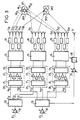
- FIG. 2 is shown a spot at two successive instants, ie SP1 and SP1 ', by conserving for example a source S13 common to these two spots.
- This signal E1 is amplified with an amplification gain controllable by the variable gain amplifier 18.
- This amplified signal is divided, into three components E11, E12, E13, of equal amplitude, in the divider 26.
- Each of these three components E11, E12, E13 is routed respectively to one of the three inputs e11, e12, e13 of three blocks 20 of high power amplification.
- the signal E11 is divided into four components of equal amplitude by the coupler 21. These components are amplified by the four amplifiers 23, recombined by the coupler 22, and routed to the output S11.
- the components E12 and E13 are amplified and routed to the outputs S12 and S13.
- the signals E11, E12 and E13 are routed to the radiating elements S11, S21, S32 respectively through switching matrices 24.
- the radiation by these sources S11, S21, and S32 of the signals E1, E2 and E3 constitutes the coverage SP1 by the three elementary spots sp11, sp21, sp32.
- the radiation area of the antenna ie the coverage SP1
- the radiation area of the antenna can be modified into an area corresponding to the coverage SP1 '(sp12, sp21, sp31 ) by switching the sources respectively (S11, S32 to S12, S31)
- This switching corresponds to a reconfiguration of two switching matrices 24, the last matrix not being reconfigured.
- This antenna reconfiguration does not affect the operation of the amplifiers 23.
- the restriction for this second signal is that it does not use the radiation sources used for the first signal.
- this amplifier stage system 20 with two inputs is compatible with two signals radiated simultaneously if and only if the sources used by these two signals at a given instant are distinct.
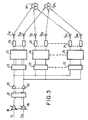
- the amplification stage 20 comprises a first and a second generalized couplers 21 and 22, respectively formed of a combination of hybrid couplers, on either side of amplifiers 23 so that each input of the first coupler 21 is distributed over all the amplifiers 23.
- a signal applied to the first input for example, spring amplified on the first output.
- the power amplifiers 23 receive on their respective inputs a signal coming from each beam, at an almost identical level.
- the amplifiers 23 thus have a constant input power and can thus operate at their nominal capacity.
- the number p of sources S ij corresponding to a channel Vi can be equal to or greater than the number m of outputs of the amplifier stage 20.
- each amplifier output is divided to supply the second couplers 22.
- the power handling of the high power stages is respected .
- a spot access Ei SPi of the input coupler corresponds to n antenna access.
- the radiation of the beam corresponding to this spot SPi is obtained by the connection through the circuit 24 corresponding to a switching matrix of each of these n accesses to the n sources of the primary network corresponding to the coverage to be achieved.
- a reconfiguration of coverage for this spot is therefore obtained by switching one, two .... or n sources: In FIG. 2 for example, with n equal to three the passage in two successive instants from spot SP1 to spot SP1 ' requiring the switching of two sources.
- An advantage of such a system is to ensure an optimum exchange of capacity: Namely that the sum of the powers distributed in the spots, whatever the relative distribution ratios, is equal to the maximum available power.
- the solution adopted is to superimpose the main radiation of the sources on the radiation of at least one additional source S 'of insulation as shown in FIG. 4.
- Such sources S' have a position in the network, such that their radiation can act predominantly in the area to be isolated. Isolation is thus ensured by using a cancellation source S 'external to the sources of the switched network.
- the amplitude (27) and the phase (28) of the latter are adjusted to obtain energy in phase opposition and of the same amplitude as that to be canceled.
- the relative level of main source / insulation source is generally less than 12 dB, which makes it possible to derive a small part of the energy of the beam concerned before the amplifier stage; fine adjustment of amplitude and phase being provided by the phase shifter 2B and the variable attenuator 27.
Landscapes
- Variable-Direction Aerials And Aerial Arrays (AREA)
- Aerials With Secondary Devices (AREA)
- Radio Relay Systems (AREA)
Claims (6)
- Konfigurierbare Sendeantenne mit mehreren Zugängen und mehreren Spots, die enthält:. m Eingänge,. einen die Energie fokussierenden Reflektor (10),. eine Gruppe von Elementarquellen, die in der fokalen Zone des Reflektors liegen, wobei jede Quelle einen Strahl aussendet,. Anschluß- und Schaltmittel (24), die die anzuregenden Quellen auswählen,. Verstärkungsmittel, die die Energie an die ausgewählten Quellen zu deren Anregung liefern, dadurch gekennzeichnet, daß. daß die Antenne n Kanäle aufweist und jeder Kanal eines der Anschluß- und Schaltmittel (24), Verstärkungsmittel mit m Eingängen und m Ausgängen sowie eine Untereinheit von Quellen aus der Gruppe von Quellen enthält,. daß die Gruppe von Elementarquellen ein Netz (11) von Quellen bildet, das die Synthese des elektromagnetischen Felds in der fokalen Zone durchführen kann,. daß die Mittel so ausgebildet sind, daß jeder Spot (SPi) von n Strahlen gebildet wird, die je von einer Gruppe von n Quellen ausgesendet werden, die von den Schaltmitteln in jeder der Untereinheiten ausgewählt werden, wobei die n Quellen jedes Spots (SPi) nebeneinander liegen und mit einer gleichen Leistung für alle n Quellen des Spots (SPi) angeregt werden und wobei die Gesamtleistung des Spots n-mal der Einheitsleistung einer Elementarquelle entspricht,. und daß jede Quelle an der Abstrahlung höchstens eines Spots in einem gegebenen Augenblick beteiligt ist.
- Antenne nach Anspruch 1, dadurch gekennzeichnet, daß sie aufweist:- m Eingänge (E₁ bis Em) entsprechend m Spots, die m Zonen auf der Erdoberfläche bestrahlen, wobei ein variabler Verstärker (18) an jeden dieser Eingänge angeschlossen ist,- und in jedem Kanal (Vi). eine Anschluß- und Schalteinheit (24) für hohen Pegel mit p Ausgängen, die jedem Spot (SP1 ... SPm) n Elementarquellen zuordnen kann, und die die Anschluß- und Schaltmittel bildet,. p Filter (25), die parallel zwischen den p Ausgängen der Anschluß- und Schalteinheit (24) und den p Quellen, die jede der Untereinheiten bilden, angeordnet sind.
- Antenne nach Anspruch 2, dadurch gekennzeichnet, daß die Verstärkungsstufe (20) einen ersten und einen zweiten allgemeinen Koppler (21 und 22) enthält, die zu beiden Seiten der Verstärker (23) parallel angeordnet sind, so daß ein an den ersten Eingang angelegtes Signal verstärkt am ersten Ausgang verfügbar ist.
- Antenne nach Anspruch 3, dadurch gekennzeichnet, daß der erste und der zweite allgemeine Koppler (21, 22) von Hybridkopplern (25) gebildet werden, so daß jeder Eingang des ersten Kopplers (21) auf alle Verstärker (23) verteilt ist und damit auch auf alle Ausgänge der Hybridkoppler des ersten allgemeinen Kopplers (21), während der zweite allgemeine Koppler (22) eine inverse Struktur zu der des ersten Kopplers besitzt.
- Antenne nach Anspruch 2, dadurch gekennzeichnet, daß sie für alle Kanäle nur einen ersten allgemeinen Koppler (21) enthält und daß der Ausgang jedes Verstärkers (23) an den gleichen Eingang von n zweiten allgemeinen Kopplern (22) angeschlossen werden kann.
- Antenne nach einem beliebigen der vorhergehenden Ansprüche, dadurch gekennzeichnet, daß sie mindestens eine zusätzliche Isolationsquelle (S') enthält.
Applications Claiming Priority (2)
| Application Number | Priority Date | Filing Date | Title |
|---|---|---|---|
| FR9014941 | 1990-11-29 | ||
| FR9014941A FR2670052B1 (fr) | 1990-11-29 | 1990-11-29 | Antenne emission reconfigurable. |
Publications (2)
| Publication Number | Publication Date |
|---|---|
| EP0488101A1 EP0488101A1 (de) | 1992-06-03 |
| EP0488101B1 true EP0488101B1 (de) | 1996-03-13 |
Family
ID=9402723
Family Applications (1)
| Application Number | Title | Priority Date | Filing Date |
|---|---|---|---|
| EP19910120044 Expired - Lifetime EP0488101B1 (de) | 1990-11-29 | 1991-11-25 | Mehrstrahlantenne mit wählbarer Konfiguration |
Country Status (5)
| Country | Link |
|---|---|
| EP (1) | EP0488101B1 (de) |
| JP (1) | JPH04291503A (de) |
| CA (1) | CA2056774A1 (de) |
| DE (1) | DE69117888T2 (de) |
| FR (1) | FR2670052B1 (de) |
Families Citing this family (3)
| Publication number | Priority date | Publication date | Assignee | Title |
|---|---|---|---|---|
| DE69221444T2 (de) * | 1991-12-10 | 1998-02-12 | Texas Instruments Inc | Einem Flugkörper angepasste Anordnung mehrerer Antennen zur Peilung mit grossem Gesichtsfeld |
| FR2729505A1 (fr) * | 1995-01-18 | 1996-07-19 | Alcatel Espace | Antenne multifaisceaux forte capacite a balayage electronique en emission |
| US6404398B1 (en) * | 2000-08-17 | 2002-06-11 | Trw Inc. | Indirect radiating array techniques |
Family Cites Families (4)
| Publication number | Priority date | Publication date | Assignee | Title |
|---|---|---|---|---|
| FR2368836A1 (fr) * | 1976-10-22 | 1978-05-19 | Matra | Dispositif de transmission radio-electrique hyperfrequence a faisceaux multiples commutables |
| DE2813916C3 (de) * | 1978-03-31 | 1981-07-30 | Siemens AG, 1000 Berlin und 8000 München | Richtantennenanordnung mit elektronisch steuerbarer Strahlschwenkung |
| FR2628896B1 (fr) * | 1988-03-18 | 1990-11-16 | Alcatel Espace | Antenne a reconfiguration electronique en emission |
| FR2652452B1 (fr) * | 1989-09-26 | 1992-03-20 | Europ Agence Spatiale | Dispositif d'alimentation d'une antenne a faisceaux multiples. |
-
1990
- 1990-11-29 FR FR9014941A patent/FR2670052B1/fr not_active Expired - Fee Related
-
1991
- 1991-11-25 DE DE1991617888 patent/DE69117888T2/de not_active Expired - Fee Related
- 1991-11-25 EP EP19910120044 patent/EP0488101B1/de not_active Expired - Lifetime
- 1991-11-28 CA CA 2056774 patent/CA2056774A1/fr not_active Abandoned
- 1991-11-29 JP JP31685691A patent/JPH04291503A/ja active Pending
Also Published As
| Publication number | Publication date |
|---|---|
| JPH04291503A (ja) | 1992-10-15 |
| DE69117888T2 (de) | 1996-07-25 |
| DE69117888D1 (de) | 1996-04-18 |
| FR2670052B1 (fr) | 1993-07-30 |
| EP0488101A1 (de) | 1992-06-03 |
| CA2056774A1 (fr) | 1992-05-30 |
| FR2670052A1 (fr) | 1992-06-05 |
Similar Documents
| Publication | Publication Date | Title |
|---|---|---|
| EP0420739B1 (de) | Speiseeinrichtung für eine Mehrkeulenantenne | |
| EP0723308B1 (de) | Mehrkeulenantenne von hoher Kapazität mit elektronisch gesteuertem Abtasten beim Senden | |
| CA1298650C (fr) | Antenne a reconfiguration electronique en emission | |
| EP0497652B1 (de) | Vorrichtung zur elektronischen Steuerung des Strahlungsdiagrammes einer Einfach-/Mehrfach-Strahlenantenne mit variabler Richtung und/oder Breite | |
| EP0368121B1 (de) | Antenne mit elektronisch gesteuerter Ablenkung | |
| US6844848B2 (en) | Wavelength division multiplexing methods and apparatus for constructing photonic beamforming networks | |
| CA1298651C (fr) | Antenne a balayage electronique | |
| EP0734093B1 (de) | Vorrichtung zur Speisung einer Mehrstrahl-Gruppenantenne | |
| EP0507688B1 (de) | Nutzlastarchitektur in der Raumfahrttechnik | |
| EP3758146B1 (de) | Analoger zweidimensionaler multipler strahlformer mit reduzierter komplexität für rekonfigurierbare aktive netzwerkantennen | |
| FR2993716A1 (fr) | Antenne d'emission et de reception multifaisceaux a plusieurs sources par faisceau, systeme d'antennes et systeme de telecommunication par satellite comportant une telle antenne | |
| US5289193A (en) | Reconfigurable transmission antenna | |
| EP1170823B1 (de) | Telekommunikationsantenne mit grossem Erdabdekkungsbereich | |
| EP0294413A1 (de) | Steuerbare strahlungskeule eines antennensystems mit butler-matrix. | |
| EP0488101B1 (de) | Mehrstrahlantenne mit wählbarer Konfiguration | |
| CA2027183C (fr) | Antenne a balayage electronique en emission | |
| EP0417679B1 (de) | Durch niedrige Schaltrate steuerbare Mehrkeulenantenne | |
| FR2533763A1 (fr) | Systeme d'antenne a faisceaux modeles, avec possibilite de modification de la configuration des faisceaux | |
| EP0638821A1 (de) | In einem Satelliten untergebrachtes Mikrowellen-Abbildungsradarsystem mit doppeltem Erfassungsbereich | |
| FR2952759A1 (fr) | Antenne a reflecteurs et reseau focal |
Legal Events
| Date | Code | Title | Description |
|---|---|---|---|
| PUAI | Public reference made under article 153(3) epc to a published international application that has entered the european phase |
Free format text: ORIGINAL CODE: 0009012 |
|
| AK | Designated contracting states |
Kind code of ref document: A1 Designated state(s): DE FR GB IT SE |
|
| 17P | Request for examination filed |
Effective date: 19921124 |
|
| 17Q | First examination report despatched |
Effective date: 19940912 |
|
| GRAA | (expected) grant |
Free format text: ORIGINAL CODE: 0009210 |
|
| AK | Designated contracting states |
Kind code of ref document: B1 Designated state(s): DE FR GB IT SE |
|
| REF | Corresponds to: |
Ref document number: 69117888 Country of ref document: DE Date of ref document: 19960418 |
|
| ITF | It: translation for a ep patent filed | ||
| PG25 | Lapsed in a contracting state [announced via postgrant information from national office to epo] |
Ref country code: SE Effective date: 19960613 |
|
| GBT | Gb: translation of ep patent filed (gb section 77(6)(a)/1977) |
Effective date: 19960529 |
|
| PLBE | No opposition filed within time limit |
Free format text: ORIGINAL CODE: 0009261 |
|
| STAA | Information on the status of an ep patent application or granted ep patent |
Free format text: STATUS: NO OPPOSITION FILED WITHIN TIME LIMIT |
|
| 26N | No opposition filed | ||
| PGFP | Annual fee paid to national office [announced via postgrant information from national office to epo] |
Ref country code: GB Payment date: 19981012 Year of fee payment: 8 Ref country code: FR Payment date: 19981012 Year of fee payment: 8 |
|
| PGFP | Annual fee paid to national office [announced via postgrant information from national office to epo] |
Ref country code: DE Payment date: 19981022 Year of fee payment: 8 |
|
| PG25 | Lapsed in a contracting state [announced via postgrant information from national office to epo] |
Ref country code: GB Free format text: LAPSE BECAUSE OF NON-PAYMENT OF DUE FEES Effective date: 19991125 |
|
| GBPC | Gb: european patent ceased through non-payment of renewal fee |
Effective date: 19991125 |
|
| PG25 | Lapsed in a contracting state [announced via postgrant information from national office to epo] |
Ref country code: FR Free format text: LAPSE BECAUSE OF NON-PAYMENT OF DUE FEES Effective date: 20000731 |
|
| PG25 | Lapsed in a contracting state [announced via postgrant information from national office to epo] |
Ref country code: DE Free format text: LAPSE BECAUSE OF NON-PAYMENT OF DUE FEES Effective date: 20000901 |
|
| REG | Reference to a national code |
Ref country code: FR Ref legal event code: ST |
|
| PG25 | Lapsed in a contracting state [announced via postgrant information from national office to epo] |
Ref country code: IT Free format text: LAPSE BECAUSE OF NON-PAYMENT OF DUE FEES;WARNING: LAPSES OF ITALIAN PATENTS WITH EFFECTIVE DATE BEFORE 2007 MAY HAVE OCCURRED AT ANY TIME BEFORE 2007. THE CORRECT EFFECTIVE DATE MAY BE DIFFERENT FROM THE ONE RECORDED. Effective date: 20051125 |