EP0488416A1 - Gerät zur Verschiebung- / Geschwindigkeit- Messung - Google Patents
Gerät zur Verschiebung- / Geschwindigkeit- Messung Download PDFInfo
- Publication number
- EP0488416A1 EP0488416A1 EP91120622A EP91120622A EP0488416A1 EP 0488416 A1 EP0488416 A1 EP 0488416A1 EP 91120622 A EP91120622 A EP 91120622A EP 91120622 A EP91120622 A EP 91120622A EP 0488416 A1 EP0488416 A1 EP 0488416A1
- Authority
- EP
- European Patent Office
- Prior art keywords
- light
- diffraction grating
- incident
- optical system
- light flux
- Prior art date
- Legal status (The legal status is an assumption and is not a legal conclusion. Google has not performed a legal analysis and makes no representation as to the accuracy of the status listed.)
- Granted
Links
- 238000006073 displacement reaction Methods 0.000 title claims abstract description 25
- 230000004907 flux Effects 0.000 claims abstract description 77
- 230000003287 optical effect Effects 0.000 claims abstract description 64
- 238000001514 detection method Methods 0.000 claims abstract description 5
- 230000014509 gene expression Effects 0.000 description 19
- 230000001419 dependent effect Effects 0.000 description 9
- 230000000694 effects Effects 0.000 description 5
- 239000012530 fluid Substances 0.000 description 5
- 238000000034 method Methods 0.000 description 5
- 239000004065 semiconductor Substances 0.000 description 4
- 238000002834 transmittance Methods 0.000 description 4
- 230000001427 coherent effect Effects 0.000 description 3
- 210000001624 hip Anatomy 0.000 description 1
- 230000001788 irregular Effects 0.000 description 1
- 238000004519 manufacturing process Methods 0.000 description 1
- 239000000203 mixture Substances 0.000 description 1
- 239000013307 optical fiber Substances 0.000 description 1
- 230000010355 oscillation Effects 0.000 description 1
- 230000005855 radiation Effects 0.000 description 1
Images


Classifications
-
- G—PHYSICS
- G01—MEASURING; TESTING
- G01S—RADIO DIRECTION-FINDING; RADIO NAVIGATION; DETERMINING DISTANCE OR VELOCITY BY USE OF RADIO WAVES; LOCATING OR PRESENCE-DETECTING BY USE OF THE REFLECTION OR RERADIATION OF RADIO WAVES; ANALOGOUS ARRANGEMENTS USING OTHER WAVES
- G01S17/00—Systems using the reflection or reradiation of electromagnetic waves other than radio waves, e.g. lidar systems
- G01S17/02—Systems using the reflection of electromagnetic waves other than radio waves
- G01S17/50—Systems of measurement based on relative movement of target
- G01S17/58—Velocity or trajectory determination systems; Sense-of-movement determination systems
Definitions
- the present invention relates to a displacement measuring apparatus for measuring the displacement information of a moving object or fluid, and more particularly to a displacement measuring apparatus for measuring the information such as a velocity by detecting the deviation of frequency of a coherent light flux such as a laser beam.
- a laser Doppler velocimeter has been known as an apparatus for measuring the movement velocity of a moving object or fluid (thereinafter referred to simply as "moving object") in non-contact and at high accuracy.
- the laser Doppler velocimeter is an apparatus for measuring the movement velocity of a moving object by directing the radiation of a laser beam to the moving object and using an effect that the frequency of scattered light by the moving object deviates (or shifts) in proportion to the movement velocity, or a so-called Doppler effect.
- Fig. 1 is a laser
- 2 is a collimator lens
- 3 is a parallel light flux
- 4 is a beam splitter
- 6 and 6' are reflecting mirrors
- 7 is a moving object moving in the arrow direction at a velocity V
- 8 is a focusing lens
- 9 is a photodetector.
- a laser beam emitted from the laser 1 is rendered the parallel light flux 3 through the collimator lens 2, and divided into two light fluxes 5 and 5' by the beam splitter 4.
- the two light fluxes 5, 5' are then reflected at the reflecting mirrors 6 and 6', respectively, and radiated onto the moving object 7 moving at a velocity V at an incident angle ⁇ , said two light fluxes overlapping.
- the scattered light by the moving object is detected via the focusing lens 8 by the photodetector 9.
- the frequencies of scattered lights from two light fluxes are subjected to the Doppler shifts of + ⁇ f and - ⁇ f, respectively, in proportion to the movement velocity V of the moving object.
- the wavelength of laser beam is ⁇ , ⁇ f can be given by the following expression (1).
- ⁇ f Vsin( ⁇ )/ ⁇ (1)
- the velocity V of the moving object 7 can be obtained by measuring the frequency F (thereinafter referred to as Doppler frequency) of the photodetector 9 from the expression (2).
- the Doppler frequency F is inversely proportional to the wavelength ⁇ of the laser beam. Accordingly, it was necessary to use a laser light source having a stable wavelength as the light source of the laser Doppler velocimeter.
- a laser light source capable of continuous emission and having a stable wavelength a gas laser such as a He-Ne laser is often used, but the laser oscillator main body is large and requires a high voltage, resulting in a large and expensive apparatus.
- a laser diode (or semiconductor laser) for use in a compact disk, a video disk or an optical fiber communication is very small and easy to drive, but has a problem that the temperature dependence exists.
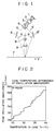
- Fig. 2 shows one example of the normal temperature dependence of a laser diode (quoted from Mitsubishi semiconductor data book, 1987: optical semiconductor devices), in which a portion with continuously changing wavelength is mainly due to the temperature variation of the refractive index in the active layer of the laser diode, and is 0.05 to 0.06 nm/°C.
- a portion with discontinuously changing wavelength is referred to as a vertical mode hopping, and is 0.2 to 0.3 nm/°C.
- a method is generally adopted in which the laser diode is controlled to be maintained at a constant temperature.
- a temperature control member such as a heater, a radiator or a temperature sensor
- the apparatus is relatively large and yields high cost, and further the instability due to previously-mentioned vertical mode hopping can not be eliminated completely.
- G-LDV method a laser Doppler velocimeter to resolve this problem in European Patent Publication EP0391278A.
- G-LDV method a method in which a laser beam from a light source such as a semiconductor laser is incident upon a diffraction grating, among obtained diffracted beams, two diffracted beams at the +n-th and -n-th order (n is 1, 2, 7) except for the zeroth order are radiated onto a moving object or flowing fluid at the same intersection angle as an angle made by the two light fluxes, and the scattered light from the moving object or flowing fluid
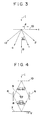
- Fig. 3 is an example of diffraction when a laser light I is incident upon a transparent diffraction grating 10 having a grating pitch d, in a direction perpendicular to the grating arranging direction t, and the diffraction angle ⁇ 0 is given by the following expression.
- sin ⁇ 0 m ⁇ /d Where m is a diffraction order (0, 1, 2, 7), and ⁇ is a wavelength of the light, in which the lights of the ⁇ n-th order except for the zeroth order can be represented by the following expression.
- sin ⁇ 0 ⁇ n ⁇ /d (3) (n: 1, 2, ).
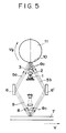
- Fig. 4 is a view in which two light fluxes of the ⁇ n-th order are radiated onto a measured object 7 with mirrors 6, 6' so that the incident angle may be ⁇ 0.
- the scattered light due to irregularities of object surface undergoes a random phase modulation, forming spot patterns, i.e., so-called speckle patterns on the observation plane.
- speckle patterns i.e., so-called speckle patterns
- the variation of contrast by the Doppler shift on a detection plane of the photodetector is modulated by irregular variations of contrast due to flow of speckle patterns, and the output signal of the photodetector is also modulated by the variation of transmittance (or reflectance) of measured object.
- the G-LDV method as previously described is generally carried out in such a way that the output of the photodetector is passed through a high-pass filter to remove low frequency components electrically in order to pick up only Doppler signals, because the frequency of the variation of contrast due to the flow of speckle patterns and the frequency of the variation of transmittance (or reflectance) for the moving object are generally a low frequency in comparison with the Doppler frequency as shown in the expression (4). But, if the Doppler frequency is low due to a slower velocity of the measured object, the frequency difference with respect to low frequency variation components is smaller, resulting in a problem that the high-pass filter can not be used and the velocity of the measured object can not be measured. Further, the movement direction can not be detected in principle.
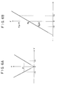
- the present applicant has proposed an apparatus having a constitution as shown in Fig. 5 in European Patent Publication EP0391278A.
- the diffraction grating having a grating pitch d is moved at a velocity Vg as shown.
- a laser beam incident upon the moving diffraction grating is divided into diffracted lights 5, 5' of the ⁇ n-th order, which then undergo positive and negative Doppler shifts ⁇ Vg/nd, respectively.
- the Doppler frequency can be sufficiently taken for a frequency difference with respect to low frequency components caused by the flow of speckle patterns or the variation of transmittance (or reflectance) of the measured object as previously described by the movement velocity Vg of the diffraction grating, and the output signal from the photodetector is passed through the high-pass filter to remove low frequency components electrically in order to pick up only the Doppler signal, whereby the detection of the velocity is enabled.
- Figs. 6A and 6B show the relation between the velocity V of the measured object and the Doppler frequency F in the laser Doppler velocimeter using the diffraction grating.
- Fig. 6A is an instance where the diffraction grating is fixed
- Fig. 6B is an instance where the diffraction grating moves at the velocity Vg.
- the movement direction can not be determined because two velocities V1, -V1 of different direction are corresponded.
- Fig. 6A shows the relation between the velocity V of the measured object and the Doppler frequency F in the laser Doppler velocimeter using the diffraction grating.
- Fig. 6A is an instance where the diffraction grating is fixed
- Fig. 6B is an instance where the diffraction grating moves at the velocity Vg.
- the present invention is an improvement in the previously-described conventional example, and the first object of the invention is to provide a displacement information measuring apparatus not dependent on the wavelength of a light as previously described, in which acoustic optical means represented by AOM is used to give a frequency difference to two light fluxes, and the acoustic optical means is disposed in a simple form with maintaining the constitution not dependent on the wavelength of the light as previously described.
- AOM acoustic optical means represented by AOM
- Fig. 1 is a view showing a conventional example of a laser Doppler velocimeter.
- Fig. 2 is a graph showing one example of the temperature dependence of the oscillation frequency for a laser diode.
- Fig. 3 is an explanation view of a diffraction grating.
- Fig. 4 is an explanation view of conventional laser Doppler velocimeter using the diffraction grating.
- Fig. 5 is an explanation view of conventional laser Doppler velocimeter with diffraction grating moving type.
- Figs. 6A and 6B are graphs showing the relation between the velocity V of moving object and the Doppler frequency F.
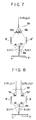
- Fig. 7 is a view for explaining the light intensity and the output of photodetector as shown in Fig. 4.
- Fig. 8 is a view for explaining the principle of the present invention.
- Fig. 9 is a view of an embodiment of the present invention.
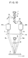
- Fig. 10 is a view for explaining another embodiment of the present invention.
- Fig. 11 is a system constitutional view of a driving system having a velocimeter shown in Fig. 9 or Fig. 10.
- Fig. 7 is a view for explaining the light intensity and the output of the photodetector 9 as shown in Fig. 4, where I0 is an incident light flux having a frequency f0 and a wavelength ⁇ .
- E1(t) and E2(t) show the scattered lights in which the diffracted lights 5a, 5b from a diffraction grating 10 are radiated onto a moving object 7 and scattered at an inclination angle ⁇ s with respect to the optical axis, and they can be represented by the following expressions, respectively:
- E1(t) A1exp[i ⁇ 2 ⁇ f0+v/ ⁇ 0(sin ⁇ 0-sin ⁇ s ) ⁇ t]
- E2(t) A2exp[i ⁇ 2 ⁇ f0-v/ ⁇ 0(sin ⁇ 0+sin ⁇ s ) ⁇ t] (8)
- Fig. 8 is a view for explaining the measuring principle of the present invention, in which I1 is a light flux having a frequency f1 and a wavelength ⁇ 1, and I2 is a light flux having a frequency f2 and a wavelength ⁇ 2.
- Fig. 9 is a constitutional view of the embodiment according to the present invention.
- 12a, 12b are wavelength shifters, using acoustic optical devices in this embodiment.
- Each acoustic optical device has a characteristic of shifting the frequency of 40 MHz for 12a, and 41 MHz for 12b.
- a laser beam 3 (frequency f0, wavelength ⁇ 0) emitted from a laser diode 1 and rendered a parallel light via collimator lens 2 is divided into two light fluxes by means of a beam splitter optical unit 13 consisting of a half mirror and a total reflection mirror. The two light fluxes are led into the acoustic optical devices 12a, 12b, respectively.
- the laser beams I1 and I2 are vertically radiated onto the diffraction grating 10 as the collimator light parallel to each other.
- the diffraction grating 10 is a blazed type, which is designed such that the laser beam I1 and the laser beam I2 may be efficiently converted into respective primary diffracted lights on the left side and the right side as viewed toward the drawing, respectively:
- the diffracted lights 5c, 5d are reflected at the mirrors 6, 6', respectively, to be incident upon a moving object 7 at the same intersection angle as an angle made with each other when they are emergent from the diffraction grating.
- the scattered lights from the moving object 7 produced at this time are efficiently led through the focusing lens 8 into the photodetector 9.
- F ⁇ f0 + 2v/d
- the absolute value on the right side of the expression (16) represents an absolute value of the velocity for the moving object 7, wherein the signs of ⁇ indicate the movement direction.
- the electrical processing is performed by an electric circuit (not shown) which is connected to the photodetector 9.
- this embodiment is provided with an illuminating unit for producing two different coherent light fluxes, a diffraction grating for forming first and second diffracted lights by diffracting the two light fluxes, an optical unit for causing the lights to be incident upon the moving object at the substantially same angle as an angle at which the first and second diffracted lights are emergent from the diffraction grating, light receiving means for receiving scattered lights from the moving object irradiated by the first and second diffracted lights, and means for detecting the displacement information of the moving object based on the Doppler signal from the light receiving means.
- an acoustic optical device is disposed at a position immediately before the position where the light flux is incident upon the diffraction grating so as to give a frequency difference to two light fluxes, the constitution not dependent upon the wavelength of the laser beam can be more easily made as compared with a case where it is disposed in the optical path after emerging from the diffraction grating.
- the constitution not dependent upon the wavelength of the laser beam as previously described must be made by adding the deflection angle when the acoustic optical device is disposed in the optical path after emerging from the diffraction grating, and thus is more complex.
- the constitution not dependent upon the wavelength of the laser light as previously described can be made in the same way as the conventional one, and is easy.
- an acoustic optical device for the frequency modulation and a diffraction grating (for making the constitution not dependent on the wavelength of the laser beam upon which the laser beam is vertically incident are separately provided, so that the freedom degree for the constitution not dependent on the wavelength of the laser beam is increased. That is, the diffraction angle for the constitution not dependent on the wavelength of the laser beam, i.e., the diffraction angle of the diffraction grating, may be determined by the constitution of the diffraction grating, and the deflection angle determined by the feature of the acoustic optical device for the frequency modulation does not have to be considered in this constitution, thereby forming the constitution more easily.
- Fig. 10 is a constitutional view of the another embodiment, wherein same numerals refer to same or like parts as in Fig. 9.
- the diffraction grating 10 is a blazed type, which is designed such that the laser beam I1 and the laser beam I2 may be efficiently converted into primary diffracted lights on the right side and the left side as viewed toward the drawing, respectively, unlike previous embodiment.
- the laser lights 5c, 5d are incident upon the moving object 7 at the same intersection angle as that angle made with each other when they has directly emerged from the diffraction grating.
- the scattered lights from the moving object 7 are efficiently led through the focusing lens 8 into the photodetector 9, which outputs the signal having a Doppler frequency F as represented in the expression (15), like the previous embodiment, so that the same effects as in the previous embodiment can be obtained.
- the reflection mirrors 6, 6' are unnecessary, a more simplification can be made as compared with the previous embodiment.
- acoustic optical devices are used to shift a difference between their frequencies, but the acoustic optical device may be diposed only in one optical path to form a light flux with the frequency shift made by the acoustic optical device and a light flux without the frequency shift, which are then radiated onto the diffraction grating.
- other acoustic optical means may be used, rather than the acoustic optical device.
- the above embodiments are apparatus for measuring the velocity of moving object, but if the velocity is integrated, the displacement can be obtained, allowing to use the apparatus as a displacement apparatus such as a so-called encoder.
- the present invention is also applicable to an instance where the velocity of small portion in the fluid is detected by narrowing two light fluxes and intersecting beam waists, as described in Europe Patent Publication EP0391278A, whereby the same effects can be obtained.
- Fig. 11 shows one example of the system having the Doppler velocimeter as above described, and is a system constitutional view of a driving system having a velocimeter to be mainly used for an image recording apparatus and an image reading apparatus.
- the moving object 100 such as a sheet is moved by driving means 102 having a driving mechanism including a driving motor and a rotating roller.
- the movement velocity or movement amount of the moving object 100 is detected by the velocimeter 101 as above described.
- the detected output of this velocimeter is fed back to control means 103, which transmits a driving signal to the driving means 102 so as to be placed in the state set by setting means 104.
- control means 103 which transmits a driving signal to the driving means 102 so as to be placed in the state set by setting means 104.
- the moving object 100 can be moved as it has been set by the setting means 104.
- Such a driving system is applicable to various machine tools or manufacturing machines, measuring instruments, video/audio apparatuses, OA
- a displacement information measuring apparatus comprising light emitting source for emitting two light fluxes, acoustic optical device for giving a predetermined frequency difference to the two light fluxes from the light emitting source, optical system having a diffraction grating upon which at least one light flux of two light fluxes having the predetermined frequency difference given by the acoustic optical device is vertically incident so that the light fluxes are diffracted, the optical system causing at least one light flux from the diffraction grating to be incident upon an object in which the displacement information is to be measured, and detector for performing a detection by interference of one light flux incident upon said object and emergent from said object with the other of the two light fluxes, the displacement information of the object being obtained from a beat signal corresponding to the frequency difference and obtained from the detector, wherein the optical system is constituted such that the frequency of the beat signal may not be substantially affected by a variation of wavelength of the light flux incident upon the diffraction grating.
Landscapes
- Physics & Mathematics (AREA)
- Electromagnetism (AREA)
- Engineering & Computer Science (AREA)
- Computer Networks & Wireless Communication (AREA)
- General Physics & Mathematics (AREA)
- Radar, Positioning & Navigation (AREA)
- Remote Sensing (AREA)
- Optical Radar Systems And Details Thereof (AREA)
- Length Measuring Devices By Optical Means (AREA)
- Optical Transform (AREA)
Applications Claiming Priority (2)
| Application Number | Priority Date | Filing Date | Title |
|---|---|---|---|
| JP2333835A JP2962819B2 (ja) | 1990-11-30 | 1990-11-30 | 変位測定装置 |
| JP333835/90 | 1990-11-30 |
Publications (2)
| Publication Number | Publication Date |
|---|---|
| EP0488416A1 true EP0488416A1 (de) | 1992-06-03 |
| EP0488416B1 EP0488416B1 (de) | 1997-06-11 |
Family
ID=18270475
Family Applications (1)
| Application Number | Title | Priority Date | Filing Date |
|---|---|---|---|
| EP91120622A Expired - Lifetime EP0488416B1 (de) | 1990-11-30 | 1991-11-29 | Gerät zur Verschiebung- oder Geschwindigkeit- Messung |
Country Status (4)
| Country | Link |
|---|---|
| US (1) | US5327222A (de) |
| EP (1) | EP0488416B1 (de) |
| JP (1) | JP2962819B2 (de) |
| DE (1) | DE69126506T2 (de) |
Cited By (4)
| Publication number | Priority date | Publication date | Assignee | Title |
|---|---|---|---|---|
| DE4424900A1 (de) * | 1994-07-15 | 1996-01-18 | Polytec Gmbh | Interferometrische Meßverfahren |
| FR2742877A1 (fr) * | 1995-12-26 | 1997-06-27 | Thomson Csf | Systeme optique de mesure de vitesse et/ou de distance d'objet |
| US10436881B2 (en) | 2015-07-01 | 2019-10-08 | Stmicroelectronics (Research & Development) Limited | Photonics device |
| US10785400B2 (en) | 2017-10-09 | 2020-09-22 | Stmicroelectronics (Research & Development) Limited | Multiple fields of view time of flight sensor |
Families Citing this family (20)
| Publication number | Priority date | Publication date | Assignee | Title |
|---|---|---|---|---|
| DE69433105T2 (de) * | 1993-06-29 | 2004-04-01 | Canon K.K. | Geschwindigkeitsmesser und Anlage zur Positionserfassung |
| JP3082533B2 (ja) * | 1993-08-23 | 2000-08-28 | キヤノン株式会社 | レーザードップラー速度計 |
| US5512745A (en) * | 1994-03-09 | 1996-04-30 | Board Of Trustees Of The Leland Stanford Jr. University | Optical trap system and method |
| JP3279116B2 (ja) * | 1994-03-22 | 2002-04-30 | 株式会社豊田中央研究所 | レーザドップラ流速計 |
| US5815267A (en) * | 1994-09-09 | 1998-09-29 | Canon Kabushiki Kaisha | Displacement information measuring apparatus in which a light-receiving condition on a photodetector is adjustable |
| JP3492012B2 (ja) * | 1995-03-09 | 2004-02-03 | キヤノン株式会社 | 変位情報検出装置 |
| JP3548275B2 (ja) * | 1995-05-12 | 2004-07-28 | キヤノン株式会社 | 変位情報測定装置 |
| JP3937596B2 (ja) | 1998-06-16 | 2007-06-27 | キヤノン株式会社 | 変位情報測定装置 |
| JP3606067B2 (ja) * | 1998-10-30 | 2005-01-05 | スズキ株式会社 | 振動測定方法および装置 |
| US6437855B1 (en) * | 2000-07-13 | 2002-08-20 | Honeywell International Inc. | Laser doppler velocimeter with high immunity to phase noise |
| US7009710B2 (en) * | 2001-08-20 | 2006-03-07 | Agilent Technologies, Inc. | Direct combination of fiber optic light beams |
| ATE309545T1 (de) * | 2002-07-05 | 2005-11-15 | Kamstrup As | Laser-doppler-anemometry mit beugenden optischen elementen |
| US7196780B2 (en) | 2003-08-08 | 2007-03-27 | Sharp Kabushiki Kaisha | Velocimeter, displacement meter, vibrometer and electronic device |
| JP4142532B2 (ja) | 2003-09-02 | 2008-09-03 | シャープ株式会社 | 光学式速度計、変位情報測定装置および搬送処理装置 |
| JP4142592B2 (ja) | 2004-01-07 | 2008-09-03 | シャープ株式会社 | 光学式移動情報検出装置およびそれを備えた電子機器 |
| CN103759753B (zh) * | 2013-12-13 | 2016-07-06 | 合肥工业大学 | 一种光栅光电信号速度测试装置 |
| CN104634254A (zh) * | 2015-03-06 | 2015-05-20 | 中国科学院光电技术研究所 | 一种基于外差干涉和二次衍射效应的光栅位移测量系统 |
| JP6660347B2 (ja) * | 2017-06-29 | 2020-03-11 | 株式会社小野測器 | レーザドップラ速度計のアダプタ、及び、レーザドップラ速度計システム |
| CN109373915B (zh) * | 2018-11-15 | 2020-07-10 | 华中科技大学 | 一种基于混沌布里渊散射的多相液体厚度测量方法及系统 |
| JP7738381B2 (ja) * | 2019-03-28 | 2025-09-12 | セイコーエプソン株式会社 | 周波数シフター型光変調器及びレーザードップラー計測装置 |
Citations (1)
| Publication number | Priority date | Publication date | Assignee | Title |
|---|---|---|---|---|
| EP0391278A2 (de) * | 1989-03-31 | 1990-10-10 | Canon Kabushiki Kaisha | Doppler-Geschwindigkeitsmesser |
Family Cites Families (2)
| Publication number | Priority date | Publication date | Assignee | Title |
|---|---|---|---|---|
| US4633714A (en) * | 1985-08-13 | 1987-01-06 | University Of Arkansas | Aerosol particle charge and size analyzer |
| US4948257A (en) * | 1987-09-14 | 1990-08-14 | Tsi Incorporated | Laser optical measuring device and method for stabilizing fringe pattern spacing |
-
1990
- 1990-11-30 JP JP2333835A patent/JP2962819B2/ja not_active Expired - Fee Related
-
1991
- 1991-11-29 DE DE69126506T patent/DE69126506T2/de not_active Expired - Lifetime
- 1991-11-29 EP EP91120622A patent/EP0488416B1/de not_active Expired - Lifetime
-
1993
- 1993-12-09 US US08/164,846 patent/US5327222A/en not_active Expired - Lifetime
Patent Citations (1)
| Publication number | Priority date | Publication date | Assignee | Title |
|---|---|---|---|---|
| EP0391278A2 (de) * | 1989-03-31 | 1990-10-10 | Canon Kabushiki Kaisha | Doppler-Geschwindigkeitsmesser |
Non-Patent Citations (2)
| Title |
|---|
| LASER UND OPTOELEKTRONIK. vol. 17, no. 4, December 1985, STUTTGART DE pages 362 - 375; B. RUCK ET AL.: 'Laser Doppler-Anemometrie' * |
| MEASUREMENT SCIENCE & TECHNOLOGY vol. 1, no. 3, March 1990, BRISTOL GB pages 265 - 271; X. GUO ET AL.: 'A new LDA system utilising the optic-hybrid feedback technique' * |
Cited By (6)
| Publication number | Priority date | Publication date | Assignee | Title |
|---|---|---|---|---|
| DE4424900A1 (de) * | 1994-07-15 | 1996-01-18 | Polytec Gmbh | Interferometrische Meßverfahren |
| FR2742877A1 (fr) * | 1995-12-26 | 1997-06-27 | Thomson Csf | Systeme optique de mesure de vitesse et/ou de distance d'objet |
| WO1997024630A1 (fr) * | 1995-12-26 | 1997-07-10 | Thomson-Csf | Systeme optique de mesure de vitesse et/ou de distance d'objet |
| US10436881B2 (en) | 2015-07-01 | 2019-10-08 | Stmicroelectronics (Research & Development) Limited | Photonics device |
| US12025745B2 (en) | 2015-07-01 | 2024-07-02 | Stmicroelectronics (Research & Development) Limited | Photonics device |
| US10785400B2 (en) | 2017-10-09 | 2020-09-22 | Stmicroelectronics (Research & Development) Limited | Multiple fields of view time of flight sensor |
Also Published As
| Publication number | Publication date |
|---|---|
| EP0488416B1 (de) | 1997-06-11 |
| US5327222A (en) | 1994-07-05 |
| JPH04204104A (ja) | 1992-07-24 |
| JP2962819B2 (ja) | 1999-10-12 |
| DE69126506T2 (de) | 1998-01-22 |
| DE69126506D1 (de) | 1997-07-17 |
Similar Documents
| Publication | Publication Date | Title |
|---|---|---|
| EP0488416A1 (de) | Gerät zur Verschiebung- / Geschwindigkeit- Messung | |
| US5640239A (en) | Optical device and displacement information measurement apparatus using the same | |
| US4336997A (en) | Change of distance measuring apparatus | |
| EP0632292B1 (de) | Geschwindigkeitsmesser und Anlage zur Positionserfassung | |
| JP2801360B2 (ja) | ドツプラ速度計 | |
| US5216478A (en) | Doppler velocity meter | |
| JP3082533B2 (ja) | レーザードップラー速度計 | |
| EP0706064A1 (de) | Verschiebungsinformationsmessgerät | |
| EP0699925B1 (de) | Optisches Gerät zur Detektion einer Verschiebung | |
| US5026162A (en) | Optical interference position measurement system | |
| US6034761A (en) | Displacement information measuring apparatus | |
| JPH0882508A (ja) | 周波数シフター及びそれを用いた光学式変位計測装置 | |
| JPH116719A (ja) | 干渉測定装置 | |
| US5272512A (en) | Displacement information detection apparatus | |
| EP0391278B1 (de) | Doppler-Geschwindigkeitsmesser | |
| JP2924301B2 (ja) | 速度計 | |
| JPH0425791A (ja) | ドップラー速度計 | |
| JP3397429B2 (ja) | 速度計及び変位情報測定装置 | |
| JP2940072B2 (ja) | ドップラー速度計 | |
| JP2911516B2 (ja) | レーザードップラー速度計 | |
| EP0458274B1 (de) | Vorrichtung und Verfahren zur Erfassung einer Information über die Verschiebung eines Gegenstands. | |
| JPH03235060A (ja) | レーザードップラー速度計 | |
| US5256885A (en) | Doppler velocimeter having a diffraction grating and dual lens groups with identical focal distances | |
| JPH07229913A (ja) | 速度計 | |
| EP0476677B1 (de) | Gerät zur Detektion von Bewegungsinformation |
Legal Events
| Date | Code | Title | Description |
|---|---|---|---|
| PUAI | Public reference made under article 153(3) epc to a published international application that has entered the european phase |
Free format text: ORIGINAL CODE: 0009012 |
|
| AK | Designated contracting states |
Kind code of ref document: A1 Designated state(s): DE FR GB IT NL |
|
| 17P | Request for examination filed |
Effective date: 19921020 |
|
| 17Q | First examination report despatched |
Effective date: 19940518 |
|
| GRAH | Despatch of communication of intention to grant a patent |
Free format text: ORIGINAL CODE: EPIDOS IGRA |
|
| GRAH | Despatch of communication of intention to grant a patent |
Free format text: ORIGINAL CODE: EPIDOS IGRA |
|
| GRAA | (expected) grant |
Free format text: ORIGINAL CODE: 0009210 |
|
| AK | Designated contracting states |
Kind code of ref document: B1 Designated state(s): DE FR GB IT NL |
|
| REF | Corresponds to: |
Ref document number: 69126506 Country of ref document: DE Date of ref document: 19970717 |
|
| ET | Fr: translation filed | ||
| PLBE | No opposition filed within time limit |
Free format text: ORIGINAL CODE: 0009261 |
|
| STAA | Information on the status of an ep patent application or granted ep patent |
Free format text: STATUS: NO OPPOSITION FILED WITHIN TIME LIMIT |
|
| 26N | No opposition filed | ||
| REG | Reference to a national code |
Ref country code: GB Ref legal event code: IF02 |
|
| PGFP | Annual fee paid to national office [announced via postgrant information from national office to epo] |
Ref country code: NL Payment date: 20081118 Year of fee payment: 18 |
|
| PGFP | Annual fee paid to national office [announced via postgrant information from national office to epo] |
Ref country code: IT Payment date: 20081119 Year of fee payment: 18 |
|
| PGFP | Annual fee paid to national office [announced via postgrant information from national office to epo] |
Ref country code: FR Payment date: 20081124 Year of fee payment: 18 |
|
| PGFP | Annual fee paid to national office [announced via postgrant information from national office to epo] |
Ref country code: GB Payment date: 20091204 Year of fee payment: 19 |
|
| REG | Reference to a national code |
Ref country code: NL Ref legal event code: V1 Effective date: 20100601 |
|
| PGFP | Annual fee paid to national office [announced via postgrant information from national office to epo] |
Ref country code: DE Payment date: 20091130 Year of fee payment: 19 |
|
| REG | Reference to a national code |
Ref country code: FR Ref legal event code: ST Effective date: 20100730 |
|
| PG25 | Lapsed in a contracting state [announced via postgrant information from national office to epo] |
Ref country code: NL Free format text: LAPSE BECAUSE OF NON-PAYMENT OF DUE FEES Effective date: 20100601 Ref country code: FR Free format text: LAPSE BECAUSE OF NON-PAYMENT OF DUE FEES Effective date: 20091130 |
|
| PG25 | Lapsed in a contracting state [announced via postgrant information from national office to epo] |
Ref country code: IT Free format text: LAPSE BECAUSE OF NON-PAYMENT OF DUE FEES Effective date: 20091129 |
|
| GBPC | Gb: european patent ceased through non-payment of renewal fee |
Effective date: 20101129 |
|
| REG | Reference to a national code |
Ref country code: DE Ref legal event code: R119 Ref document number: 69126506 Country of ref document: DE Effective date: 20110601 Ref country code: DE Ref legal event code: R119 Ref document number: 69126506 Country of ref document: DE Effective date: 20110531 |
|
| PG25 | Lapsed in a contracting state [announced via postgrant information from national office to epo] |
Ref country code: DE Free format text: LAPSE BECAUSE OF NON-PAYMENT OF DUE FEES Effective date: 20110531 |
|
| PG25 | Lapsed in a contracting state [announced via postgrant information from national office to epo] |
Ref country code: GB Free format text: LAPSE BECAUSE OF NON-PAYMENT OF DUE FEES Effective date: 20101129 |