EP0488639A1 - Obturateur pour buse et procédé pour obturer une buse d'un générateur de vapeur - Google Patents
Obturateur pour buse et procédé pour obturer une buse d'un générateur de vapeur Download PDFInfo
- Publication number
- EP0488639A1 EP0488639A1 EP91310862A EP91310862A EP0488639A1 EP 0488639 A1 EP0488639 A1 EP 0488639A1 EP 91310862 A EP91310862 A EP 91310862A EP 91310862 A EP91310862 A EP 91310862A EP 0488639 A1 EP0488639 A1 EP 0488639A1
- Authority
- EP
- European Patent Office
- Prior art keywords
- nozzle
- sections
- dam
- section
- central section
- Prior art date
- Legal status (The legal status is an assumption and is not a legal conclusion. Google has not performed a legal analysis and makes no representation as to the accuracy of the status listed.)
- Granted
Links
Images

Classifications
-
- F—MECHANICAL ENGINEERING; LIGHTING; HEATING; WEAPONS; BLASTING
- F16—ENGINEERING ELEMENTS AND UNITS; GENERAL MEASURES FOR PRODUCING AND MAINTAINING EFFECTIVE FUNCTIONING OF MACHINES OR INSTALLATIONS; THERMAL INSULATION IN GENERAL
- F16L—PIPES; JOINTS OR FITTINGS FOR PIPES; SUPPORTS FOR PIPES, CABLES OR PROTECTIVE TUBING; MEANS FOR THERMAL INSULATION IN GENERAL
- F16L55/00—Devices or appurtenances for use in, or in connection with, pipes or pipe systems
- F16L55/10—Means for stopping flow in pipes or hoses
- F16L55/115—Caps
- F16L55/1152—Caps fixed by screwing or by means of a screw-threaded ring
-
- G—PHYSICS
- G21—NUCLEAR PHYSICS; NUCLEAR ENGINEERING
- G21C—NUCLEAR REACTORS
- G21C19/00—Arrangements for treating, for handling, or for facilitating the handling of, fuel or other materials which are used within the reactor, e.g. within its pressure vessel
-
- F—MECHANICAL ENGINEERING; LIGHTING; HEATING; WEAPONS; BLASTING
- F22—STEAM GENERATION
- F22B—METHODS OF STEAM GENERATION; STEAM BOILERS
- F22B37/00—Component parts or details of steam boilers
- F22B37/02—Component parts or details of steam boilers applicable to more than one kind or type of steam boiler
- F22B37/22—Drums; Headers; Accessories therefor
- F22B37/221—Covers for drums, collectors, manholes or the like
- F22B37/222—Nozzle dams introduced through a smaller manway, e.g. foldable
-
- G—PHYSICS
- G21—NUCLEAR PHYSICS; NUCLEAR ENGINEERING
- G21C—NUCLEAR REACTORS
- G21C13/00—Pressure vessels; Containment vessels; Containment in general
- G21C13/02—Details
- G21C13/06—Sealing-plugs
-
- Y—GENERAL TAGGING OF NEW TECHNOLOGICAL DEVELOPMENTS; GENERAL TAGGING OF CROSS-SECTIONAL TECHNOLOGIES SPANNING OVER SEVERAL SECTIONS OF THE IPC; TECHNICAL SUBJECTS COVERED BY FORMER USPC CROSS-REFERENCE ART COLLECTIONS [XRACs] AND DIGESTS
- Y02—TECHNOLOGIES OR APPLICATIONS FOR MITIGATION OR ADAPTATION AGAINST CLIMATE CHANGE
- Y02E—REDUCTION OF GREENHOUSE GAS [GHG] EMISSIONS, RELATED TO ENERGY GENERATION, TRANSMISSION OR DISTRIBUTION
- Y02E30/00—Energy generation of nuclear origin
- Y02E30/30—Nuclear fission reactors
Definitions
- the present invention relates to a nozzle dam and process for closing off a nozzle of a steam generator, and more parlicularly to a multi-section nozzle dam which is remotely installed over an internal portion of the primary fluid nozzles within the channel head of a nuclear steam generator.
- a typical nuclear steam generator comprises a vertically oriented shell or vessel.
- a tube sheet adjacent the lower end of the vessel supports a tube bundle comprising a plurality of tubes, each generally in the shape of an inverted U.
- the portion of the vessel beneath the tube sheet is divided by a partition into inlet and outlet plenums which are respectively disposed immediately beneath the vertical legs of the tube bundle.
- the vessel is provided with primary fluid inlet and outlet nozzles, respectively communicating with the plenums, each nozzle projecting outwardly of the vessel and commonly having a frusto-conical portion and a cylindrical portion.
- the nozzles are connected by conduits to an associated nuclear reactor vessel.
- Primary fluid having been heated by circulation through the reactor enters the steam generator vessel through the primary inlet nozzle to the inlet plenum and from there flows upwardly through the tube bundle to the outlet plenum and then through the outlet nozzle to the reactor core.
- the tube bundle above the tube sheet is immersed in a secondary fluid, such as water, the tube bundle serving as a heat exchanger for converting the secondary water to steam, which is then used for generating electricity in the usual manner.
- the reactor Periodically, it is necessary to shut down the reactor for refueling. This is usually a convenient time for servicing the nuclear steam generator.
- the reactor is drained to below the level of the inlet and outlet nozzles of the steam generator vessel.
- the tube bundle and inlet and outlet plena are also drained and dams are then installed in the inlet and outlet nozzles to block them.
- the steam generator vessel can then be treated in a chemical decontamination procedure without contaminating the primary fluid conduits and the nuclear reactor.
- the inlet nozzle of the steam generator vessel must be closed off. This is accomplished by use of the nozzle seal or dam which is installed in the nozzle from inside the inlet plenum of the generator vessel.
- U.S. Patent No. 4,667,701 issued to Evens et al. discloses a multi-section nozzle dam which is hingedly connected to the inner periphery of the inlet nozzle.
- a frame is secured to the inlet nozzle and the multiple nozzle dam segments are secured thereto.
- a sealing diaphragm is initially positioned over the uppermost segment and once each section has been secured to the frame, the diaphragm is drawn over the remaining segments.
- the nozzle dam of U.S. Patent No. 4,667,601 must be manually secured within the plenum of the steam generator and consequently subjects maintenance personnel to significant radiation exposure.
- the frame is continuously exposed to contaminants.
- nozzle dam for sealing off the nozzles of the channel head of a nuclear steam generator.
- nozzle dam which may be both reliably and remotely installed, positioned and secured over the nozzle of" the nuclear steam generator such that maintenance personnel are exposed to minimal amounts of radiation.
- the invention in its broad form is a nozzle dam for closing off a nozzle of a steam generator, said nozzle dam characterized by at least two substantially planar sections together forming a substantially planar surface, said surface being of a greater diameter than an inner opening of the nozzle; a bolt for securing each of said sections to an inner surface of the steam generator about a periphery of said inner opening of the nozzle; and a seal positioned between said sections and the inner surface of the steam generator for forming a fluid tight seal about the inner nozzle opening.
- the nozzle dam in accordance with the present invention includes a mounting ring mounted on an inner surface of the steam generator about a periphery of the inner opening of the nozzle, at least one substantially planar central section and two substantially planar side sections together forming a substantially planar surface, the surface being of a greater diameter than the inner opening of the nozzle.
- Securing devices are also provided about the periphery of each of the sections for securing each of the sections to the mounting ring after all the sections are positioned over the inner opening of the nozzle.
- sealing gasket which is secured to the central section with the sealing gasket having a diameter substantially equal to the diameter of the substantially planar surface formed by the sections for forming a fluid tight seal between a periphery of the substantially planar surface and the inner surface of the steam generator about the periphery of the inner opening of the nozzle.
- Each of the sections are initially passed through the manway of the steam generator. Once inside the channel head of the nuclear steam generator, the central section of the nozzle dam is retrieved by a robotic arm and positioned over a central portion of the nozzle opening. The robotic arm then positions the remaining side sections over the opening. Once each of the sections are aligned and positioned on the mounting ring, a bolt torque mechanism is then attached to the robotic arm and integral hold down bolts of the sections are sequentially tightened.
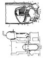
- a typical pressurized water reactor 1 is illustrated which is connected to a typical nuclear steam generator 2 by way of a conduit 3.
- the refueling pool 4 is flooded, for purposes of refueling, with water to a level 5 which is significantly above the position of the inlet nozzle 6 of the nuclear steam generator, and; consequently, a nozzle dam 7 must be securely positioned over the inlet nozzle 6 in order to reliably isolate the nuclear steam generator 2 from the pressurized water reactor 1.
- the placement of the nozzle dam 7 within the nuclear steam generator 2 must be carried out prior to the flooding of the refueling pool 4.
- FIG. 2 there is illustrated a portion of the nuclear steam generator 2 which includes a vessel 11 having a generally partial spherical lower end which is separated from the upper end thereof by a horizontally disposed tubesheet 12.
- a tube bundle 13 including a plurality of generally inverted U-shaped tubes 14 having the lower ends thereof disposed through complimentary bores in the tubesheet 12.
- the portion of the vessel 11 below the tubesheet 12 is divided by a wall 15 into an inlet plenum 16 and an outlet plenum 17, which respectively communicate with the two vertical portions of the tubes 14.
- Formed in the vessel 11 are manways (one shown) which provide access to the inlet and outlet plenum 16 and 17.
- each of the nozzles 20 and 21 each having an outer cylindrical portion 22 having a cylindrical inner surface 23 and an inner frusto-conical portion 24 having a frusto-conical inner surface 25.
- the outer end of each of the nozzles 20 and 21 defines an annular wall 26 which is adapted to be secured as by a suitable weldment 70 to the associated conduit 3 as illustrated in Figure 5, which extends to the pressurized water reactor 1 as illustrated in Figure 1.
- nozzles In general, there are presently two types of nozzles which may exist in existing steam generator vessels. One type has a relatively long cylindrical portion 22 and a relatively short frusto-conical portion 24, this type being exemplified by the nozzle 20, while another type has a relatively short cylindrical portion 22 and a relatively long frusto-conical portion 24. This type being exemplified by nozzle 21. With the typical nuclear steam generator, the vessel 11 will include nozzles of the same type; however, both types have been illustrated in Figure 2 for the purposes of illustration. Moreover, the nozzle dam of the present invention may be readily adapted to either type of nozzle.
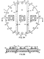
- the nozzle dam 7 in accordance with the present invention consists of three sections, each being a segment of a circular disk, a right section 28, a left section 30 and a central section 32.
- Each of the sections 28-32 include a centrally located adapter 34, the significance of which will be discussed in greater detail hereinbelow, allows each of the sections to be remotely manipulated by a remote control mechanical arm 56 (see Fig. 4), such as the ROSA III mechanical arm developed by the assignee of the present invention.
- the dam sections are manufactured of light weight composite material such as carbon filament epoxy, kevlar epoxy, or aluminum honeycomb.
- each section has a thickness of approximately 50.8 mm, and an overall diameter of 1054.1 mm.
- Each of the nozzle dam sections 28 and 30 include seven bores 36 mutually spaced about the periphery of the outer sections which accommodate integral hold down bolts 58 illustrated in Figure 3C, for remotely securing the outer plates 28, 30 to a pre-installed ring 66 mounted above the nozzle inside the steam generator.
- the central section 32 includes bores 38 about its periphery which likewise accommodate integral hold down bolts for securing the central section to the pre-installed ring.
- a guide pin is incorporated into the central topmost bolt 40 and the central lowermost bolt 42 to aid in centering the dam on the pre-installed bolting ring. Also included in each of the outer sections 28 and 30 are guide bores 44 which receive guide pins 46 (illustrated in Figure 4) in order to align each of the outer sections 28 and 30 with the central section 32 upon placement over the nozzle within the nuclear steam generator.
- each of the outer sections 28 and 30 include step sections 48 which overlie the step sections 50 of the central section 32 when the nozzle dam 7 is in its final applied state.
- a gasket 52 is positioned to underlie the entire bottom surface of the nozzle dam 7 and includes cooperating bores 54 which mate with the bores 36 and 38 of each of the nozzle dam sections in order to allow the passage of the integral hold down bolts.
- FIG 3C is an expanded illustration of one of the integral hold down bolts referred to above, mounted on the side section 28.
- the integral hold down bolt 58 extends through the bore 36 formed in the side section as well as the bore 54 formed in the gasket 52.
- the hold down bolt 58 is retained in place by a capture plate 60 which is secured to the upper surface of the side section 28 by fastening means 62.
- the hold down bolt 58 is biased by way of a spring washer 64 which allows a torque tool to press and rotate the integral hold down bolt once the bolts have been aligned with respective bores of the pre-installed ring mounted within the nuclear steam generator.
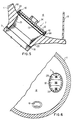
- the central section 32 is illustrated in its initial condition wherein the robotic arm 56 is coupled by way of the adapter 34 to the central section 32 in order to manipulate the central section 32 within the nuclear steam generator.
- the joint between the central section 32 of the nozzle dam 7 and the robotic arm 56 which is used to lift the dam sections into place is preferably an electromagnetic connection.
- other devices such as mechanical, pneumatic or vacuum joints may be readily adapted to form the connection between the robotic arm 56 and the central section 32 in order to manipulate the sections within the nuclear steam generator.
- the full diameter sealing gasket 52 is attached to and is an integral part of the central section 32 of the nozzle dam 7.
- the central section 32 of the nozzle dam 7 is the first section to be positioned over the pre-installed ring.
- the two outer sections 28 and 30 which mechanically overlap the central section 28 are subsequently installed.
- the outer sections include a significant arcuate outer periphery, they are more rigid than the central section and; consequently, the step connection between the outer sections 28 and 30 and the central section 32 adds to the rigidity of the central section and the ability of the entire nozzle dam 7 to withstand a significant pressure while being of a light weight.
- the sections of the nozzle dam are secured to the pre-installed ring 66 which is secured to the inner surface 68 of the nuclear steam generator.
- Figure 5 illustrates the nozzle dam being positioned over the nozzle which extends from the plenum 16 of the nuclear steam generator, such a nozzle dam may be readily positioned over the nozzle 21 which communicates with the plenum 17.
- the nozzle dam 7 is secured such that it spans the entire opening of the nozzle and thereby reliably seals off the nozzle 20 and prohibits the ingress or egress of fluid therethrough.
- the nozzle 20 is secured to the conduit 3 by way of the weldment 70.
- Figure 6 illustrates the nozzle dam 7 in its completely erect condition covering the nozzle which extends from the plenum 16 of the nuclear steam generator. Also illustrated in this Figure is the manhole 19 which provides access to the plenum 16.
- the nozzle dam as mentioned above is divided into three approximately equal sections which are sized to pass through the manway of the steam generator.
- the central section 32 of the nozzle dam 7 is retrieved by the robotic arm 56 and positioned over a central portion of the nozzle.
- the full diameter sealing gasket 52 is attached to and is an integral part of the central dam section and, consequently, covers the entire nozzle once the central nozzle dam section 32 is in place.
- the robotic arm 56 aligns the upper central alignment pin and lower central alignment pin of the central section 32 with the pre-installed ring 66 thus ensuring the proper installation of the central section.
- the robotic arm 56 releases the central section and retrieves one of the side sections 28, 30. This section is then placed in its proper position over the gasket material and is aligned with the central section 32 by mating the mating pins 46 of the central section 32 with the respective bore 44 of the side section. Once in position, the robotic arm releases this section and subsequently retrieves the final side section and places this section alongside the central section 32 as with the previous side section.
- a bolt torque mechanism is attached to the robotic arm and the integral hold down bolts of the central section and side sections are sequentially tightened. Once tightened, the refueling pool 4 may be flooded while maintenance procedures are carried out within the steam generator.
- the nozzle dam may be readily removed. The removal of the nozzle dam is carried out in the reverse order of its installation described above.
- the nozzle dam 7 in accordance with the present invention may be remotely installed thereby eliminating the manned entry required for the installation of present nozzle dams and thus minimizes the exposure of maintenance personnel to radiation. Moreover, the nozzle dam in accordance with the present invention will reliably and securely seal-off the nozzle to assure a secure environment within the steam generator for carrying out various maintenance procedures.
Landscapes
- Engineering & Computer Science (AREA)
- General Engineering & Computer Science (AREA)
- Physics & Mathematics (AREA)
- Mechanical Engineering (AREA)
- Plasma & Fusion (AREA)
- High Energy & Nuclear Physics (AREA)
- Thermal Sciences (AREA)
- Monitoring And Testing Of Nuclear Reactors (AREA)
- Turbine Rotor Nozzle Sealing (AREA)
- Devices For Medical Bathing And Washing (AREA)
Applications Claiming Priority (2)
| Application Number | Priority Date | Filing Date | Title |
|---|---|---|---|
| US07/618,127 US5238054A (en) | 1990-11-26 | 1990-11-26 | Steam generator nozzle dam |
| US618127 | 1990-11-26 |
Publications (2)
| Publication Number | Publication Date |
|---|---|
| EP0488639A1 true EP0488639A1 (fr) | 1992-06-03 |
| EP0488639B1 EP0488639B1 (fr) | 1995-05-10 |
Family
ID=24476425
Family Applications (1)
| Application Number | Title | Priority Date | Filing Date |
|---|---|---|---|
| EP91310862A Expired - Lifetime EP0488639B1 (fr) | 1990-11-26 | 1991-11-26 | Obturateur pour buse et procédé pour obturer une buse d'un générateur de vapeur |
Country Status (4)
| Country | Link |
|---|---|
| US (1) | US5238054A (fr) |
| EP (1) | EP0488639B1 (fr) |
| KR (1) | KR920010660A (fr) |
| ES (1) | ES2073130T3 (fr) |
Cited By (2)
| Publication number | Priority date | Publication date | Assignee | Title |
|---|---|---|---|---|
| GB2259745B (en) * | 1991-09-20 | 1995-01-11 | Westinghouse Electric Corp | Sealing a conduit end |
| FR2708080A1 (fr) * | 1993-07-19 | 1995-01-27 | Framatome Sa | Ensemble de fermeture étanche d'une tubulure de jonction d'une enceinte et d'une canalisation et son utilisation. |
Families Citing this family (8)
| Publication number | Priority date | Publication date | Assignee | Title |
|---|---|---|---|---|
| JPH05288516A (ja) * | 1992-04-07 | 1993-11-02 | Honda Motor Co Ltd | 非接触式位置検出装置 |
| US6672257B1 (en) | 1994-05-06 | 2004-01-06 | Foster-Miller, Inc. | Upper bundle steam generator cleaning system and method |
| US5564371A (en) * | 1994-05-06 | 1996-10-15 | Foster Miller, Inc. | Upper bundle steam generator cleaning system and method |
| AU2002231151A1 (en) * | 2000-12-21 | 2002-07-01 | Foster-Miller Inc. | Steerable delivery system |
| FR2940398B1 (fr) * | 2008-12-22 | 2013-07-05 | Areva Np | Obturateur d'une ouverture d'une tubulure de jonction d'une enceinte et d'une canalisation, notamment d'un generateur de vapeur d'un reacteur a eau sous pression |
| FR2941031B1 (fr) * | 2009-01-14 | 2011-02-11 | Areva Np | Obturateur etanche d'une ouverture d'une tubulure de jonction d'une enceinte et d'une canalisation et procede pour la mise en oeuvre d'un tel obturateur |
| US20190057788A1 (en) * | 2017-01-30 | 2019-02-21 | Exelon Generation Company, Llc | Jet pump plug seal and methods of making and using same |
| KR102003161B1 (ko) | 2018-07-12 | 2019-07-23 | 한국수력원자력 주식회사 | 증기발생기 노즐 개폐장치 |
Citations (5)
| Publication number | Priority date | Publication date | Assignee | Title |
|---|---|---|---|---|
| FR2340489A1 (fr) * | 1976-02-09 | 1977-09-02 | Framatome Sa | Dispositif d'obturation d'un orifice |
| FR2545971A1 (fr) * | 1983-05-11 | 1984-11-16 | Thome Jean Patrick | Methode et dispositif d'obturation du circuit primaire de reacteurs nucleaires |
| FR2562310A1 (fr) * | 1984-03-28 | 1985-10-04 | Field Automation Sarl | Methode et dispositif d'obturation du circuit primaire de reacteurs nucleaires |
| FR2574975A1 (fr) * | 1984-12-18 | 1986-06-20 | Thome Jean Patrick | Obturation du circuit primaire de reacteurs nucleaires depuis les generateurs de vapeur |
| FR2595668A1 (fr) * | 1986-03-17 | 1987-09-18 | Bertin & Cie | Dispositif d'obturation d'un orifice a l'interieur d'une enceinte accessible seulement par un autre orifice de dimensions inferieures a celles de l'orifice a obturer |
Family Cites Families (12)
| Publication number | Priority date | Publication date | Assignee | Title |
|---|---|---|---|---|
| US4436692A (en) * | 1982-02-10 | 1984-03-13 | Automation Industries, Inc. | Plug for reactor pressure vessel nozzle |
| US4584162A (en) * | 1982-03-31 | 1986-04-22 | Preferred Utilities Manufacturing Corp. | Pipe plug and remote installation equipment therefor |
| US4624824A (en) * | 1982-12-15 | 1986-11-25 | The Babcock & Wilcox Company | Reactor vessel sealing plug |
| US4671326A (en) * | 1984-09-17 | 1987-06-09 | Westinghouse Electric Corp. | Dual seal nozzle dam and alignment means therefor |
| JPH0238164Y2 (fr) * | 1984-11-15 | 1990-10-16 | ||
| US4667701A (en) * | 1984-12-27 | 1987-05-26 | Nuclear Energy Systems, Inc. | Nozzle dam assembly |
| US4672741A (en) * | 1985-06-27 | 1987-06-16 | Westinghouse Electric Corp. | End effector apparatus for positioning a steam generator heat exchanger tube plugging tool |
| US4690172A (en) * | 1985-12-17 | 1987-09-01 | Westinghouse Electric Corp. | Foldable dual-seal nozzle dam |
| US4684491A (en) * | 1986-01-09 | 1987-08-04 | Westinghouse Electric Corp. | Nozzle seal retaining assembly and positioning assembly therefor |
| US4954312A (en) * | 1988-12-15 | 1990-09-04 | Combustion Engineering, Inc. | Remotely installed steam generator nozzle dam system |
| US4957215A (en) * | 1989-02-13 | 1990-09-18 | Cliff Evans | Segmented nozzle dam |
| US4959192A (en) * | 1989-06-13 | 1990-09-25 | Tennesse Valley Authority | Nozzle dam translocating system |
-
1990
- 1990-11-26 US US07/618,127 patent/US5238054A/en not_active Expired - Fee Related
-
1991
- 1991-11-25 KR KR1019910021113A patent/KR920010660A/ko not_active Withdrawn
- 1991-11-26 ES ES91310862T patent/ES2073130T3/es not_active Expired - Lifetime
- 1991-11-26 EP EP91310862A patent/EP0488639B1/fr not_active Expired - Lifetime
Patent Citations (5)
| Publication number | Priority date | Publication date | Assignee | Title |
|---|---|---|---|---|
| FR2340489A1 (fr) * | 1976-02-09 | 1977-09-02 | Framatome Sa | Dispositif d'obturation d'un orifice |
| FR2545971A1 (fr) * | 1983-05-11 | 1984-11-16 | Thome Jean Patrick | Methode et dispositif d'obturation du circuit primaire de reacteurs nucleaires |
| FR2562310A1 (fr) * | 1984-03-28 | 1985-10-04 | Field Automation Sarl | Methode et dispositif d'obturation du circuit primaire de reacteurs nucleaires |
| FR2574975A1 (fr) * | 1984-12-18 | 1986-06-20 | Thome Jean Patrick | Obturation du circuit primaire de reacteurs nucleaires depuis les generateurs de vapeur |
| FR2595668A1 (fr) * | 1986-03-17 | 1987-09-18 | Bertin & Cie | Dispositif d'obturation d'un orifice a l'interieur d'une enceinte accessible seulement par un autre orifice de dimensions inferieures a celles de l'orifice a obturer |
Cited By (2)
| Publication number | Priority date | Publication date | Assignee | Title |
|---|---|---|---|---|
| GB2259745B (en) * | 1991-09-20 | 1995-01-11 | Westinghouse Electric Corp | Sealing a conduit end |
| FR2708080A1 (fr) * | 1993-07-19 | 1995-01-27 | Framatome Sa | Ensemble de fermeture étanche d'une tubulure de jonction d'une enceinte et d'une canalisation et son utilisation. |
Also Published As
| Publication number | Publication date |
|---|---|
| EP0488639B1 (fr) | 1995-05-10 |
| ES2073130T3 (es) | 1995-08-01 |
| US5238054A (en) | 1993-08-24 |
| KR920010660A (ko) | 1992-06-27 |
Similar Documents
| Publication | Publication Date | Title |
|---|---|---|
| US4678623A (en) | Modular head assembly and method of retrofitting existing nuclear reactor facilities | |
| EP0488639B1 (fr) | Obturateur pour buse et procédé pour obturer une buse d'un générateur de vapeur | |
| US5706319A (en) | Reactor vessel seal and method for temporarily sealing a reactor pressure vessel from the refueling canal | |
| EP0175221B1 (fr) | Fermeture à deux joints pour buse | |
| CA1306314C (fr) | Methode d'instrumentation de reacteurs nucleaires et dispositif correspondant | |
| EP0005177B1 (fr) | Procédé et appareil pour retirer un faisceau tubulaire | |
| JPH0682590A (ja) | 原子炉の一体形ヘッドパッケージ | |
| CN102803819B (zh) | 用于压力容器进入闭合件的凸起的膜/嵌入板 | |
| US4567016A (en) | Venting means for nuclear reactors | |
| US5037604A (en) | Coffer dam for temporary shielding of reactor vessel internals | |
| US4192053A (en) | Method for retubing a steam generator | |
| JPH06300883A (ja) | 原子炉圧力容器の上蓋 | |
| US4214760A (en) | Seal for adjacent plates | |
| US4801423A (en) | Radiation shielding door assembly | |
| US4345549A (en) | Steam-generator with improved facilities for replacement of parts | |
| US4954312A (en) | Remotely installed steam generator nozzle dam system | |
| CA1179612A (fr) | Calorifugeage cintre pour extremites de recipients sous pression | |
| US4910823A (en) | Cleaning mechanism for penetration interfaces in nuclear pressure vessels | |
| US5032350A (en) | System for installing a steam generator nozzle dam | |
| US6932117B2 (en) | Reactor water isolation devices | |
| US4750554A (en) | Internal tube sheet sealing apparatus assembly for tubular heat exchangers | |
| US5646969A (en) | Apparatus for installing tie rod assembly in space between jet pump assemblies with limited vertical access | |
| US4684492A (en) | Repair fixture | |
| US4859409A (en) | Reactor vessel lower internals temporary support | |
| KR19980069929A (ko) | 헤드 영역의 케이블 트레이 브리지 |
Legal Events
| Date | Code | Title | Description |
|---|---|---|---|
| PUAI | Public reference made under article 153(3) epc to a published international application that has entered the european phase |
Free format text: ORIGINAL CODE: 0009012 |
|
| AK | Designated contracting states |
Kind code of ref document: A1 Designated state(s): BE CH ES FR GB IT LI SE |
|
| 17P | Request for examination filed |
Effective date: 19921119 |
|
| 17Q | First examination report despatched |
Effective date: 19940302 |
|
| GRAA | (expected) grant |
Free format text: ORIGINAL CODE: 0009210 |
|
| AK | Designated contracting states |
Kind code of ref document: B1 Designated state(s): BE CH ES FR GB IT LI SE |
|
| PGFP | Annual fee paid to national office [announced via postgrant information from national office to epo] |
Ref country code: FR Payment date: 19950519 Year of fee payment: 5 |
|
| ET | Fr: translation filed | ||
| ITF | It: translation for a ep patent filed | ||
| REG | Reference to a national code |
Ref country code: ES Ref legal event code: FG2A Ref document number: 2073130 Country of ref document: ES Kind code of ref document: T3 |
|
| PGFP | Annual fee paid to national office [announced via postgrant information from national office to epo] |
Ref country code: GB Payment date: 19951127 Year of fee payment: 5 |
|
| PGFP | Annual fee paid to national office [announced via postgrant information from national office to epo] |
Ref country code: ES Payment date: 19951129 Year of fee payment: 5 Ref country code: BE Payment date: 19951129 Year of fee payment: 5 |
|
| PGFP | Annual fee paid to national office [announced via postgrant information from national office to epo] |
Ref country code: SE Payment date: 19951130 Year of fee payment: 5 |
|
| PGFP | Annual fee paid to national office [announced via postgrant information from national office to epo] |
Ref country code: CH Payment date: 19951221 Year of fee payment: 5 |
|
| PLBE | No opposition filed within time limit |
Free format text: ORIGINAL CODE: 0009261 |
|
| STAA | Information on the status of an ep patent application or granted ep patent |
Free format text: STATUS: NO OPPOSITION FILED WITHIN TIME LIMIT |
|
| 26N | No opposition filed | ||
| PG25 | Lapsed in a contracting state [announced via postgrant information from national office to epo] |
Ref country code: GB Effective date: 19961126 |
|
| PG25 | Lapsed in a contracting state [announced via postgrant information from national office to epo] |
Ref country code: SE Effective date: 19961127 Ref country code: ES Free format text: LAPSE BECAUSE OF NON-PAYMENT OF DUE FEES Effective date: 19961127 |
|
| PG25 | Lapsed in a contracting state [announced via postgrant information from national office to epo] |
Ref country code: LI Effective date: 19961130 Ref country code: CH Effective date: 19961130 Ref country code: BE Effective date: 19961130 |
|
| BERE | Be: lapsed |
Owner name: WESTINGHOUSE ELECTRIC CORP. Effective date: 19961130 |
|
| REG | Reference to a national code |
Ref country code: CH Ref legal event code: PL |
|
| GBPC | Gb: european patent ceased through non-payment of renewal fee |
Effective date: 19961126 |
|
| PG25 | Lapsed in a contracting state [announced via postgrant information from national office to epo] |
Ref country code: FR Effective date: 19970731 |
|
| EUG | Se: european patent has lapsed |
Ref document number: 91310862.7 |
|
| REG | Reference to a national code |
Ref country code: FR Ref legal event code: ST |
|
| REG | Reference to a national code |
Ref country code: ES Ref legal event code: FD2A Effective date: 19971213 |
|
| PG25 | Lapsed in a contracting state [announced via postgrant information from national office to epo] |
Ref country code: IT Free format text: LAPSE BECAUSE OF NON-PAYMENT OF DUE FEES;WARNING: LAPSES OF ITALIAN PATENTS WITH EFFECTIVE DATE BEFORE 2007 MAY HAVE OCCURRED AT ANY TIME BEFORE 2007. THE CORRECT EFFECTIVE DATE MAY BE DIFFERENT FROM THE ONE RECORDED. Effective date: 20051126 |