EP0488829A2 - Tintenbehälter und Aufzeichnungskopf mit einem solchen Behälter - Google Patents
Tintenbehälter und Aufzeichnungskopf mit einem solchen Behälter Download PDFInfo
- Publication number
- EP0488829A2 EP0488829A2 EP91311211A EP91311211A EP0488829A2 EP 0488829 A2 EP0488829 A2 EP 0488829A2 EP 91311211 A EP91311211 A EP 91311211A EP 91311211 A EP91311211 A EP 91311211A EP 0488829 A2 EP0488829 A2 EP 0488829A2
- Authority
- EP
- European Patent Office
- Prior art keywords
- ink
- absorbing material
- absorbing
- recording head
- container
- Prior art date
- Legal status (The legal status is an assumption and is not a legal conclusion. Google has not performed a legal analysis and makes no representation as to the accuracy of the status listed.)
- Granted
Links
Images


Classifications
-
- B—PERFORMING OPERATIONS; TRANSPORTING
- B41—PRINTING; LINING MACHINES; TYPEWRITERS; STAMPS
- B41J—TYPEWRITERS; SELECTIVE PRINTING MECHANISMS, i.e. MECHANISMS PRINTING OTHERWISE THAN FROM A FORME; CORRECTION OF TYPOGRAPHICAL ERRORS
- B41J2/00—Typewriters or selective printing mechanisms characterised by the printing or marking process for which they are designed
- B41J2/005—Typewriters or selective printing mechanisms characterised by the printing or marking process for which they are designed characterised by bringing liquid or particles selectively into contact with a printing material
- B41J2/01—Ink jet
- B41J2/17—Ink jet characterised by ink handling
- B41J2/175—Ink supply systems ; Circuit parts therefor
- B41J2/17503—Ink cartridges
- B41J2/1752—Mounting within the printer
- B41J2/17523—Ink connection
-
- B—PERFORMING OPERATIONS; TRANSPORTING
- B41—PRINTING; LINING MACHINES; TYPEWRITERS; STAMPS
- B41J—TYPEWRITERS; SELECTIVE PRINTING MECHANISMS, i.e. MECHANISMS PRINTING OTHERWISE THAN FROM A FORME; CORRECTION OF TYPOGRAPHICAL ERRORS
- B41J2/00—Typewriters or selective printing mechanisms characterised by the printing or marking process for which they are designed
- B41J2/005—Typewriters or selective printing mechanisms characterised by the printing or marking process for which they are designed characterised by bringing liquid or particles selectively into contact with a printing material
- B41J2/01—Ink jet
- B41J2/17—Ink jet characterised by ink handling
- B41J2/175—Ink supply systems ; Circuit parts therefor
- B41J2/17503—Ink cartridges
- B41J2/17506—Refilling of the cartridge
-
- B—PERFORMING OPERATIONS; TRANSPORTING
- B41—PRINTING; LINING MACHINES; TYPEWRITERS; STAMPS
- B41J—TYPEWRITERS; SELECTIVE PRINTING MECHANISMS, i.e. MECHANISMS PRINTING OTHERWISE THAN FROM A FORME; CORRECTION OF TYPOGRAPHICAL ERRORS
- B41J2/00—Typewriters or selective printing mechanisms characterised by the printing or marking process for which they are designed
- B41J2/005—Typewriters or selective printing mechanisms characterised by the printing or marking process for which they are designed characterised by bringing liquid or particles selectively into contact with a printing material
- B41J2/01—Ink jet
- B41J2/17—Ink jet characterised by ink handling
- B41J2/175—Ink supply systems ; Circuit parts therefor
- B41J2/17503—Ink cartridges
- B41J2/17513—Inner structure
-
- B—PERFORMING OPERATIONS; TRANSPORTING
- B41—PRINTING; LINING MACHINES; TYPEWRITERS; STAMPS
- B41J—TYPEWRITERS; SELECTIVE PRINTING MECHANISMS, i.e. MECHANISMS PRINTING OTHERWISE THAN FROM A FORME; CORRECTION OF TYPOGRAPHICAL ERRORS
- B41J2/00—Typewriters or selective printing mechanisms characterised by the printing or marking process for which they are designed
- B41J2/005—Typewriters or selective printing mechanisms characterised by the printing or marking process for which they are designed characterised by bringing liquid or particles selectively into contact with a printing material
- B41J2/01—Ink jet
- B41J2/17—Ink jet characterised by ink handling
- B41J2/175—Ink supply systems ; Circuit parts therefor
- B41J2/17503—Ink cartridges
- B41J2/17556—Means for regulating the pressure in the cartridge
Definitions
- the present invention relates to an ink container and a recording head having the same usable with a recording apparatus for effecting recording operation using liquid ink in the form of a copying machine, fascimile machine, printer, compound machines or the like.
- U.S. Patents Nos. 4,095,237 and 4,306,245 disclose an ink container accommodating a liquid absorbing material occupying a part or entirety of the inside space thereof.
- an end of the ink supply pipe communicating with an ink jet recording head is enclosed by a porous elastic material, and therefore, the ink supply performance is quite satisfactory, and is practically advantageous from the standpoint of preventing influences of the air introduced into the container.
- U.S. Patent No. 4,164,744 discloses a structure in which a coloring material is stored in a sealed container. This relates to a printing pen, and therefore, the introduction of the air in accordance with the consumption of the ink as in the case of the ink jet recording is not recognized.
- U.S. Patent No. 3,967,286 discloses an example using plural ink absorbing materials, more particularly an ink absorbing material in an ink container movable together with the recording head and a wick contacted to the ink absorbing material.
- plural ink absorbing materials more particularly an ink absorbing material in an ink container movable together with the recording head and a wick contacted to the ink absorbing material.
- it does not recognize the problem of the air introduction when the ink absorbing material is opened to the air.
- U.S. Patent No. 4,368,478 discloses provision of porous material in a common liquid chamber and/or ink container of the ink absorbing portion, and discloses that the fibers are suspended in the ink at a position upstream of the porous material in the direction of the ink supply so as to prevent the porous material from being clogged with the air bubbles. This however deals with the bubbles having passed through the ink supply pipe, but does not disclose the prevention of the introduction of the air into the recording head itself. This would be because the mechanism of the introduction of the bubbles is not analyzed sufficiently. It seams to base on the assumption that the introduced air is immediately conveyed into the recording head from the ink supply container. It involves the problem that the fibers and filler materials are deposited on the inner wall of the container and the problem of the insufficient ink supply when the number of ejection outlets is increased or when the apparatus is driven at a high speed.
- the ink supply container capable of sufficiently supplying the ink for driving more than 10 ejection outlets or at the frequency not less than 5 KHz.
- the present invention relates to the problems of the introduction of the air in accordance with the consumption of the ink.
- the invention starts from the finding that as long as one porous ink absorbing material is used, there is a limit in delaying the arrival of the air to the ink outlet portion (as seen from the ink supply container) along the inside of the absorbing material or along between the container wall and the absorbing material, and therefore, there is a limit to the reduction of the amount of the unusably remaining ink.
- an ink container comprising: an ink discharging portion for discharging ink; an air vent; first liquid absorbing material for absorbing the ink therein; a second ink absorbing material, disposed between said air vent and said first absorbing material, for absorbing the ink, said first and second absorbing materials being at least partly contacted to each other.
- said partition member is of flexible resin material enclosing the fibrous material and compressing them in a direction crossing with lengths of the fibrous materials; and said first absorbing material comprises a number of fibrous material compressed in a direction crossing with the lengths of the fibrous material, and a peripheral portion of a bundle of the fibrous material is contacted to said second absorbing material.
- an ink jet recording head comprising: a recording head having more than 10 ejection outlets for ejecting ink and electrothermal transducers for the respective ejection outlets for creating bubbles through a film boiling by thermal energy and a common chamber for supplying the ink to the ejection outlets; an ink supply member for supplying the ink to the common chamber and provided with a filter at an ink receiving end thereof; a discharging portion for discharging the ink to the ink receiving end for said ink supply member; an air vent; a first absorbing material for aborbing ink therein, said first absorbing material comprising a number of fibrous materials in a compressed state and a flexible resin material enclosing member having an opening for exposing said fibrous materials, said first absorbing material exhibiting ink guiding property; a second absorbing material for absorbing the ink, disposed between said air vent and said first absorbing material, said second absorbing material being contacted to the fibr
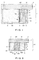
- Figure 1 is a sectional view of an ink jet recording head according to an embodiment of the present invention.
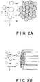
- Figure 2A schematically shows the mechanism of the air bubble introduction into a bundle of fibers (ink guiding members), when the air bubble is not capable of entering the bundle of the fibers.
- Figure 2B shows the same when the slight amount of the air bubbles can enter the bundle of the fibers, but the prevention is better than the conventional case.
- Figure 3 is a sectional view of an ink jet recording head according to another embodiment of the present invention.
- Figures 4A and 4B are a sectional view and a perspective view of an ink container.
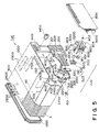
- Figure 5 is a recording head assembly having the ink container shown in Figure 4, the head assembly being detachably mountable.
- Figure 6 is an exploded perspective view showing the internal structures of the ink accommodating container according to an embodiment of the present invention.
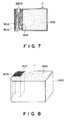
- Figure 7 is a sectional view showing the position and configuration of the absorbing material in the ink container and the position of the ink supply pipe.
- Figure 8 shows the internal structures of the ink accommodating container, which is a modification of Figure 6 embodiment.
- Figure 9 shows a structure of an ink container constituting an ink jet recording head.
- Figure 10 shows an ink jet cartridge according to an embodiment of the present invention.
- Figure 11 is a perspective view of an ink jet cartridge.
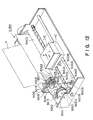
- Figure 12 is a schematic view of an ink jet recording apparatus.
- Figure 13A and 13B show a first ink absorbing material according to an embodiment of the present invention.
- Figures 14A and 14B show fibers extending in one direction, according to an embodiment of the present invention.
- Figure 15 shows the ink container, according to an embodiment of the present invention.
- Figure 16 shows an ink container illustrating a method of filling it with the ink.
- Figure 17 shows a major part in the method of Figure 16.
- Figure 18 shows a driving mechanism for a recording head.
- FIG. 1 there is shown in cross-section an ink jet recording head according to an embodiment of the present invention.
- the recording head 1 comprises a main assembly having an ink ejecting function which will be described hereinafter and an integral ink container 3 for supplying the recording ink to the main assembly 2.
- the ink container 3 functions to contain the recording liquid and has a partition wall 4 for providing a first chamber 3A adjacent the main assembly and a second chamber 3B adjacent an air vent of the container, the partition wall 4 being integral with the casing of the container 3.
- the partition wall 4 extends substantially parallel to the wall portion 12A of the first chamber 3A.
- a partial opening 4A is formed substantially at the center of the partition wall 4 so that the two chambers communicate with each other.
- an end of a supply pipe 9 communicating with the main assembly 2 is inserted.
- the end of the supply pipe 9 is provided with a filter 8 for preventing introduction of foreign matter into an ink passage 10.
- the other end of the supply pipe 10 constitutes an ink discharger 7.
- the second chamber 3B is provided with an opening 11 communicating with the ambience (air vent).
- the second chamber 3B of the ink container 3 is filled with a sponge 5 (second liquid absorbing material) made of continuous fine porous material such as polyurethane or the like having sufficient elasticity and liquid absorbing property.
- the first chamber 3A is filled with fibers 6 (first absorbing material) in the form of a bundle of polyester resin fibers compressed an extended in the same direction.
- the fibers 6 extend in the direction toward the end of the supply pipe 9 for the recording head, although they may be vent partially.
- This direction is advantageous since the ink supply property is improved.
- the fibers are compressed within a proper range, the ink guiding properties are enhanced in accordance with the consumption of the ink, and therefore, the supply of the ink into the bundle of the fibers is better, and the long term ink supply is assured. Even if the air bubbles are introduced, the good ink guiding property is effective to exclude the bubbles from the bundle of the fibers. This is also advantageous from the standpoint of the ink supply.
- the directions in which the fibers are extended is substantially parallel with the wall surface of the partition wall 4 and the wall portion 12A of the first chamber 3A.
- the longitudinal end portions of the fibers are assuredly contacted to the other wall portions 12B and 12C of the first chamber 3A which are perpendicular to the above wall surfaces.
- the central portion of the bundle of fibers at an end is in contact with one surface of the filter 8 for the supply pipe 9, as shown in the Figure.
- the central portion is press-contacted to the surface.
- the opening 4A of the partition wall 4 is away from the end of the supply pipe 9 by a proper distance, but they are sufficiently close to each other.
- the ink jet recording head 1 in accordance with the ejection of the ink from the ink ejector 7, the ink is gradually consumed from the neighborhood of the filter at the end of the supply pipe 9.
- the ink retained in the bundle of the fibers is subjected to the capillary force in the direction of the fibers, since the number of fibers are bundled and are extended in the same direction. Because of the capillary force, the ink smoothly moves along the fibers to the filter 8, and are assuredly supplied from the end of the ink supply pipe 9 to the ink ejector 7 having an unshown ink ejecting means.
- the ink can be assuredly supplied to the ink ejector.
- the ink when the recording head is directed downwardly, the ink is supplied from the upper position, and is further supplied to the recording head by the fibers.
- the ink container may be sealed from the ambient air.
- the ink contained in the sponge 5 in the second chamber 3B is supplied by the vacuum through the opening 4A of the partition wall 4 to that portion of the fibers in the first chamber 3A which is in contact with the sponge 5.
- the air enters the second chamber 3B through the air vent 11 so as to balance the pressures in the first and second chambers 3A and 3B, thus assuring the continuous supply of the ink.
- the ink supply to the recording head is accomplished by the fibers 6, and the sponge 5 is between the fibers and the air vent.
- the fibers and the sponge are in contact with or in press-contact with each other. Those two points are effective to delay the motion of the air in the container so that the ink can be more efficiently supplied to the recording head.
- the fibers 6 are better than the sponge 5 in all of the capillary force, the ink retaining characteristics and the air excluding characteristics. Therefore, the introduction of the ink mainly occurs in the sponge 5 or the space between the sponge and the inner wall surface, so that the arrival of the air at the first chamber 3A can be significantly delayed. Therefore, the quantity of the wasteful ink which remains unusably in the container can be minimized.
- the sponge 5 and the fibers 6 are directly contacted through the opening 4A, the ink movement from the sponge 5 to the fibers 6 is smooth.
- the opening 4A is defined by the partition wall 4, and therefore, the opening is defined by the material which is more rigid than the sponge or the fibers, and therefore, not easily deformed.
- the thickness of the wall 4 is preferably small, but it still has a certain thickness. Therefore, one or both of the sponge 5 and the fibers 6 are bulged into the opening.
- the opening area is not less than 100 mm2, more particularly, 200 mm2, and therefore, both of them are bulged for direct contact therebetween ( Figure 1).
- Figures 7A and 7B show examples of the structures usable with the present invention, but the structure of Figure 7A is preferable. The preferable one is used in this embodiment.
- the reference X indicates the direction in which the ink moves from the sponge 5 to the fibers 6, and therefore, the air bubble or bubbles also move in the direction X.
- the periphery of the bundle of the fibers 6, that is, the side of the bundle is contacted to the sponge 5.
- the direction of the ink supply from the sponge crosses with the ink guiding direction of the bundle of fibers.
- the opening 4A of the partition wall 4 is formed at a position away from the supply pipe 9 inlet by a proper distance, the ink in the sponge 5 is supplied through the opening 4A and is once retained by the fibers 6, and only then the ink is supplied to the ink ejector 7 through the supply pipe 9.
- This is also advantageous in that the introduction of the air from the sponge 5 into the ink ejector 7.
- FIG. 3 is a sectional view of an ink jet recording head according to another embodiment of the present invention.
- reference numeral 60 designates the ink jet recording head.
- the structure of the recording head 60 is substantially the same as the recording head 1 of Figure 1, and therefore, the same reference numerals are assigned to the elements having the corresponding functions, and the detailed description thereof is omitted for simplicity.
- the ink container 3 is provide with two partition walls 61 and 62 which are integral with the inner wall of the ink container 3. By the two partition walls 61 and 62. there are provided one first chamber 3A and two second chambers 3B and 3C adjacent and at the opposite sides of the first chamber 3A.
- the first and second partition walls 61 and 62 are provided with partial openings 61A and 62A substantially at the center thereof.
- an end of a supply pipe 9 in communication with the ink passage 10 and therefore, with the ink ejector 7 is inserted so that the portion of the ink pipe 9 extends parallel with the partition walls 61 and 62.
- the end of the supply pipe 9 is provide with the filter 8.
- fibers 6 are extended in the manner that the direction of the fibers are parallel with the partition walls 61 and 62 and that the central portion of one end of the bundle of the fibers is contacted to a surface of the filter 8 at the end of the supply pipe 9.
- the second chambers 3B and 3C are filled with sponges 5, respectively.
- the air vent 11 is provided only for 3B of the second chambers, but the air vent is also provided for the other second chamber 3A.
- the first absorbing material 5 and the second absorbing material 6 are directly contacted through the two openings 61A and 62A, respectively, so that the ink is smoothly supplied from the absorbing materials 5 to the absorbing material 6.
- the ink is gradually consumed from the neighborhood of the filter 8. Since the fibers 6 are extended in the same direction, the capillary forces are applied along the fibers. By the capillary force, the ink smoothly moves along the fibers to the filter 8.
- the ink is supplied to the ink ejector 7 by the ink ejecting means not shown by way of the supply pipe 9.
- the ink contained in the first absorbing material 5 in the second chambers 3B and 3C is supplied to the second absorbing material 6 in the first chamber 3A through the openings 61A and 62A of the partition walls 61 and 62. They are, similarly consumed for the recording.
- the air enters the second chamber 2B through the air vent 11, so that the pressures in the first chamber 3A and in the second chambers 3B and 3C, are balanced, by which the ink supply is assured.
- the opening area may be larger than in the first embodiment, the ink supply from the sponge 5 to the fibers 6 is more efficient. Since the sponges 5 and the fibers 6 are directly contacted to each other through the openings 61A and 62A, and therefore, the ink movement is small. The contacts at the respective positions between the fibers 6 and the sponges 5, are the same as in the case of Figure 2A.
- the partition in the ink container is provide by the partition walls 61 and/or 62, but the partition may be provided inside ribs or a member joined to the inside surface of the container.
- the partition member may be in the form of a flexible elastic sheet mounted in the ink container.
- the state of ink, temperature or another ambient condition may be accomodated by the deformation of the elastic sheet so that the ink supply can be maintained.
- the partition wall may be in the form of a cylinder in which the bundle of fibers is disposed, and porous material having the elasticity and liquid absorbing characteristics may be disposed between the partition wall and the ink container.
- Figures 4A, 4B and 5 shows an embodiment in which the partition member is integral with the fibers or the absorbing material, but is not fixed on the inside of the ink container.
- the fibers and the sponge providing the vacuum in the ink supply action are freely deformed when receiving the ink.
- the stabilized vacuum and therefore, the ink supply is stabilized.
- the partition member By the partition member, the deformation of the fibers can be suppressed to stabilize the vacuum.
- the partition member usable with this embodiment may be in the form of a sheer, plate.
- it may be resin or aluminum sheet enclosing the fibers mostly to retard movement of the air or to stop it.
- Figures 4A and 4B are sectional view and perspective view of the ink container of a partition sheet according to an embodiment of the present invention.
- FIG reference 1A designates an ink container.
- the inside of the ink container 1A is divided into two chambers by the partition member 40 having the partial opening 40A. Adjacent the ink discharging portion of the ink container, the portion (one of the chambers) connected to the communicating pipe 9 is filled with fibers 6.
- the other chamber is filled with a porous material 5 having elasticity and liquid absorbing property.
- an air vent 11 is formed.
- the partition member 40 is made of flexible sheet, more particularly, polyethylene resin material in this embodiment.
- the ink is supplied through the pipe 9, and the quantity of the image inside the ink container 1A decreases in accordance with the ink supply. To permit this, the space of the ink is replaced with the air through the air vent 11.
- the supply pipe 5 is isolated by the partition member 40, and by the capillary action of the fibers 6, the neighborhood of the pipe 9 is filled with the ink, so that the ink supply is stabilized.
- the partition member 40 since the partition member 40 is made of flexible sheet, it can flexibly follow the internal pressure between the two materials 5 and 6 due to the supply of the ink, so that the contact between the fibers 6 and the porous material 5 is stabilized.
- the ink supply direction by the fibers and the ink supply direction by the porous sponge cross with each other, as in Figure 2A example.
- the elastic porous material is usually compressed in the container and increases its volume when the air is introduced thereinto as a result of the ink consumption. To the contrary, the spaces between fibers expand when the ink is absorbed. When the ink is discharged therefrom, the spaces contract. Therefore, even if the volume of the bundle of the fibers changes slightly, the pressure by the porous material in the direction crossing with the fiber direction increases with the ink supply to the bundle of the fibers. This is effective to maintain the good contact between them, and is also effective to maintain the capillary force by the fibers. Therefore, the ink supply to the ink container is stabilized for a long period of time.
- FIG 5 shows a bubble jet cartridge BD01 available from Canon Kabushiki Kaisha, Japan having the ink container 1A shown in Figures 4A and 4B. The detailed description thereof will be made hereinafter in conjunction with Figures 10, 11 and 12. Here, the major parts only will be described.
- An ink jet cartridge IJC has a cartridge main assembly 1000, an integral ink jet unit IJU and an integral ink jet head IJH.
- the cartridge main assembly 1000 comprises the bundle of fibers, a partition member 40 having an opening 40A, a porous material 900 in the order named with compression.
- the ink supply from the container to the head IJH is effected through an ink supply pipe 2200 penetrating the supply port 1200 and through an ink conduit 1600 to the ink inlet port 1500 of the common chamber.
- the ink jet head IJH forms a bubble using thermal energy, as will be described hereinafter to eject the ink. It comprises plural ejection outlets and effects on-demand recording at high frequency. With the use of the ink container 1A, the ink can be stably supplied to the recording head from the ink container, and therefore, the bubble creation using the film boiling, can be stabilized.
- the above embodiment uses a flexible sheet, but the same advantageous effects are provided when a flexible tube enclosing the fibers is used. It is preferable that the fibers are compressed in the tube, since then the bundle of the fibers can be easily mounted in the ink container.
- Figures 4 and 5 embodiment is preferable in that the second absorbing material which is controlling with respect to the vacuum but which is deformed when receiving the ink from the first absorbing material or which is locally deformed, can be stabilized in the formation of the vacuum and in the supply of the ink.
- the formation of the second absorbing material is suppressed by the partition member, and the vacuum is stabilized.
- the contact between the first absorbing material and the second absorbing material can be stabilized, and the movement of the air or the like between the absorbing materials can be prevented.
- Figures 6, 7 and 8 shows the embodiment wherein a member enclosing the fibers is used.
- the fibers are uniformly distributed relative to the ink discharging portion, and is advantageous in that the ink supply is made uniform to the ink discharging portion.
- the bundle of fibers and the porous material are simultaneously mounted in the ink container, by which the deformation of the bundle of the fibers is prevented, thus stabilizing the contact between the absorbing materials.
- the ink can be supplied thereafter with stability without remaining the air, by which the ink communication at the contact portion is stabilized.
- FIG 6 shows an exploded view of the ink container.
- the porous material 900 is different from the foregoing embodiments is cut at a corner to accommodate the bundle of the fibers.
- an opening 904 of the cylindrical partition member is contracted with good close-contactness with the fibers 902.
- the ink container comprises the porous material 900 for retaining the ink, a bundle of fibers 902 for retaining a constant amount of the ink, a tube for holding the fibers 902 and functioning as a partition member press-contacted to the porous material 901 and made of flexible material, an ink supply port 904 for supplying the ink from the porous material 900 to the fibers 902.
- the supply port 904 is formed in the tube 903.
- Figure 7 shows the ink container having the absorbing material 901 in the ink container 1000, and an ink supply pipe 2200 for the ink jet unit IJU inserted in the fibers 902.
- the porous material 900 is made of polyurethane or the like capable of retaining the ink. It is preferably provided with inclined or recessed portion for permitting deformation of the fibers 902.
- the contact between the porous material 900 and the bundle of the fibers 902 may be made at plural surfaces or by a curved surface, rather than a single flat surface, so that the ink is stably supplied.
- the bundle of fibers 902 functions to retain a sufficient quantity of the ink to supply the ink from the porous material 900 to the ink supply pipe 2200 of the ink jet unit IJU.
- the fibers in this example are made of polyester resin or the like which provides large capillary force and which prevents introduction of the air.
- the direction of the fibers 902 are made parallel with the direction of the ink supply pipe 2200.
- the outside of the bundle of the fibers is enclosed with a flexible tube 903 made of polyethylene or the like.
- the ink is smoothly supplied to the ink jet unit, and in addition, the air coming along the internal surface of the ink container IT can be stopped so as not to introduce the air into the absorbing material.
- the ink supply pipe 2200 can perform its function if it is inserted into the bundle of the fibers 902.
- the end of the ink supplu pipe 2200 is press-contacted to the bundle 902. The press-contact is also preferable to maintain the stabilized ink supply.
- the porous material 900 and the bundle 902 are simultaneously mounted into the ink container IT.
- the simultaneous mounting the undesirable deformation of the bundle 902 can be prevented, and the contact area between the porous material 901 and the bundle 902 can be stabilized.
- the non-uniform distribution of the ink can be prevented.
- the air is prevented from remaining, thus assuring the ink movement through the contact area is assured.
- the constant quantity of the ink can be retained at all times in the bundle of fibers adjacent the end of the ink supply pipe 2200 for supplying the ink to the ink jet head unit IJU. Therefore, the insufficient supply of the ink to the ink jet unit IJU can be prevented.
- the bundle 902 retains the ink by the capillary action, and therefore, the retaining characteristics are immune to the temperature, humidity, pressure and impact thereto. Therefore, the conventional problem of the insufficient ink supply due to the ink retaining charateristics change resulting from the change in the ambient condition, can be prevented.
- Figure 8 shows the ink container according to a further embodiment of the present invention.
- the bundle of the fibers 902 is in the form of a rectanglular cylinder.
- the porous material 900 has a rectangular cut-away portion. The cut-away portion receives the bundle of fibers 902 enclosed with the partition member.
- the bundle having the rectangular cross-section is also usable with the same advantageous effects as in the foregoing embodiments.
- the fibers are disposed between the inside surface of the container and the porous material to stably position the fibers relative to the porous material, thus preventing insufficient ink supply.
- Using the porous material enclosing the bundle of the fibers, is preferable in that the ink retaining or ink supplying performance to the contact area is enhanced, so that the efficiency of the ink supply is improved.
- the formation of the air layer can be prevented between the ink absorbing material and the ink supply pipe of the recording head, and therefore, the deterioration of the resultant image or the occurence of the ejection failure can be assuredly prevented.
- the ink consumption for the recovery operation can be reduced, and the reliability of the ink jet cartridge is significantly improved.
- the ink absorbing material in the recording liquid container comprises a first absorbing material exhibiting higher liquid absorbing property and disposed adjacent to the recording liquid supplying pipe (ink discharging side) and a second absorbing material exhibiting lower ink absorbing property than the first liquid absorbing material.
- the first absorbing material and the second absorbing material are at least partly contacted to each other so as to provide the vacuum.
- Figure 9 shows an ink container constituting a part of the liquid jet recording head.
- the ink jet cartridge IJC of this embodiment has a large ink absorbing region by projecting the ink jet unit IJU slightly beyond the front surface of the ink container IT.
- the ink jet cartridge IJC is supported by an unshown positioning means of the carriage HC in the ink jet recording apparatus main assembly IJRA and by electric contacts.
- the ink jet cartridge IJC is detachably mountable to the carriage HC, wherein the ink can be refilled.
- the ink jet unit IJU is of an ink jet recording type using electrothermal transducers which generate thermal energy, in response to electric signals, to produce film boiling of the ink.
- the unit comprises a heater board 100 having electrothermal transducers (ejection heaters) arranged in a line on an Si substrate and electric head lines made of aluminum or the like to supply electric power thereto.
- the electrothermal transducer and the electric leads are formed by a film forming process.
- a wiring board 200 is associated with the heater board 100 and includes wiring corresponding to the wiring of the heater board 100 (connected by the wire bonding technique, for example) and pads 201 disposed at an end of the wiring to receive electric signals from the main assembly of the recording apparatus.
- a top plate 1300 is provided with grooves which define partition walls for separting adjacent ink passages and a common liquid chamber for accommodating the ink to be supplied to the respective ink passages.
- the top plate 1300 is formed integrally with an ink jet opening 1500 for receiving the ink supplied from the ink container IT and directing the ink to the common chamber, and also with an orifice plate 400 having the plurality of ejection outlets corresponding to the ink passages.
- the material of the integral mold is preferably polysulfone, but may be another molding resin material.
- a supporting member 300 is made of metal, for example, and functions to support a backside of the wiring board 200 in a plane, and constitutes a bottom plate of the ink jet unit IJU.
- a confining spring 500 is in the form of "M" having a central portion urging to the common chamber with a light pressure, and a clamp 501 urges concentratedly with a line pressure to a part of the liquid passage, preferably the part in the neighborhood of the ejection outlets.
- the confining spring 500 has legs for clamping the heater board 100 and the top plate 1300 by penetrating through the openings 3121 of the supporting plate 300 and engaging the back surface of the supporting plate 300.
- the supporting plate 300 has positioning openings 312, 1900 and 2000 engageable with two positioning projections 1012 and positioning and fuse-fixing projections 1800 anf 1801 of the ink container IT. It further includes projections 2500 and 2600 at its backside for the positioning relative to the carriage HC of the main assembly IJRA.
- the supporting member 300 has a hole 320 through which an ink supply pipe 2200, which will be described hereinafter, is penetrated for supplying ink from the ink container.
- the wiring board 200 is mounted on the supporting member 300 by bonding agent or the like.
- the supporting member 300 is provided with recesses 2400 and 2400 adjacent the positioning projections 2500 and 2600.
- the assembled ink jet cartridge IJC has a head projected portion having three sides provided with plural parallel grooves 3000 and 3001.
- the recesses 2400 and 2400 are located at extensions of the parallel grooves at the top and bottom sides to prevent the ink or foreign matter moving along the groove from reaching the projections 2500 and 2600.
- the covering member 800 having the parallel grooves 3000 constitutes an outer casing of the ink jet cartridge IJC and cooperates with the ink container to define a space for accommodating the ink jet unit IJU.
- the ink supply member 600 having the parallel groove 3001 has an ink conduit pipe 1600 communicating with the above-described ink supply pipe 2200 and cantilevered at the supply pipe 2200 side. In order to assure the capillary action at the fixed side of the ink conduit pipe 1600 and the ink supply pipe 2200, a sealing pin 602 is inserted.
- a gasket 601 seals the connecting portion between the ink container IT and the supply pipe 2200.
- a filter 700 is disposed at the container side end of the supply pipe.
- the ink supply member 600 is molded, and therefore, it is produced at low cost with high positional accuracy.
- the cantilevered structure of the conduit 1600 assures the press-contact between the conduit 1600 and the ink inlet 1500 even if the ink supply member 600 is mass-produced.
- the complete communicating state can be assuredly obtained simply by flowing sealing bonding agent from the ink supply member side under the press-contact state.
- the ink supply member 600 may be fixed to the supporting member 300 by inserting and penetrating backside pins (not shown) of the ink supply member 600 through the openig 1901 and 1902 of the supporting member 300 and by heat-fusing the portion where the pins are projected through the backside of the supporting member 300.
- the slight projected portions thus heat-fused are accommodated in recesses (not shown) in the ink jet unit (IJU) mounting side surface of the ink container IT, and therefore, the unit IJU can be correctly positioned.
- the ink container comprises a main body 1000, a first ink absorbing material 900, a second ink absorbing material 902 and a cover member 1100 for sealing the cartridge after the absorbing materials 901 are inserted through a side opposite from the unit mounting side of the assembly 1000.
- the ink absorbing material 900 is inserted into the main body 1000 from the side opposite from the unit (IJU) mounting side, and thereafter, the cover member 1100 seals the main body.
- the second absorbing material 902 is enclosed with a flexible sheet 903 having an opening (not shown), and the opening portion is press-contacted to the first ink absorbing material 900, when it is disposed in the main assembly 1000.
- An ink supply opening 1200 functions to supply the ink to the unit IJU comprising the various elements 100 - 600.
- the opening also functions as an injection port for supplying the ink to the absorbing materials 900 and 902 therethrough before the unit is mounted to the portion 1010 of the main assembly 1000 of the cartridge.
- the ink may be supplied through an air vent port and this supply opening.
- ribs 2300 is formed on the inside surface of the main body 1000, and ribs 2301 and 2302 are formed on the inside of the cover member 1100, which are effective to provide within the ink container an ink existing region extending continuously from the air vent port side to that corner portion of the main body which is most remote from the ink supply opening 1200.
- the number of the ribs 2300 in this embodiment is four, and the ribs 2300 extend parallel to a movement direction of the carriage adjacent the rear side of the main body of the ink container, by which the absorbing material 900 is prevented from closely contacted to the inner surface of the rear side of the main body.
- the partial ribs 2400 and 2500 are formed on the inside surface of the cover member 1100 at a position which is substantially an extension of the ribs 2300, however, as contrasted to the large rib 2300, the size of the ribs 2301 an 2302 are small as if it is divided ribs, so that the air existing space is larger with the ribs 2400 and 2500 than with the rib 2300.
- the ribs 2302 and 2301 are distributed on the entire area of the cover member 1100, and the area thereof is not more than one half of the total area.
- the cartridge is provided with an air vent port 1401 for communication between the inside of the cartridge with the outside air. Inside the vent port 1401, there is a water stopping material 1400 to prevent the inside ink from leaking outside through the vent port 1401.
- the ink accommodating space in the ink container IT is substantially rectangular parallelepiped, and the long side faces in the direction of carriage movement, and therefore, the above-described rib arrangements are particularly effective.
- the ribs are preferably formed on the entire surface of the inside of the cover member 1100 to stabilize the ink supply from the ink absorbing material 900.
- the cube configuration is preferable from the standpoint of accommodating as much ink as possible in the limited space.
- the provisions of the ribs formed on the two surfaces constituting a corner are particularly effective.
- the inside ribs 2301 and 2302 of the ink container IT are substantially uniformly distributed in the direction of the thickness of the ink absorbing material having the rectangular parallelepiped configuration.
- Such a structure is significant, since the air pressure distribution in the ink container IT is made uniform when the ink in the absorbing material is consumed so that the quantity of the remaining unavailable ink is substantially zero.
- the ribs are disposed on the surface or surfaces outside a circular are having the center at the projected position on the ink supply opening 1200 on the top surface of the rectangular ink absorbing material and having a radius which is equal to the long side of the rectangular shape, since then the ambient air pressure is quickly established for the ink absorbing material present outside the circular arc.
- the position of the air vent of the ink container IT is not limited to the position of this embodiment if it is good for introducing the ambient air into the position where the ribs are disposed.
- the ink jet cartridge IJC After the ink jet cartridge IJC is assembled, the ink is supplied from the inside of the cartridge to the chamber in the ink supply member 600 through a supply opening 1200, the whole 320 of the supporting member 300 and an inlet formed in the backside of the ink supply member 600. From the chamber of the ink supply member 600, the ink is supplied to the common chamber through the outlet, supply pipe and an ink inlet 1500 formed in the top plate 1300.
- the connecting portion for the ink communication is sealed by silicone rubber or butyl rubber or the like to assure the hermetical seal.
- the top plate 1300 is made of resin material having resistivity to the ink, such as polysulfone, polyether sulfone, polyphenylene oxide, polypropylene. It is integrally molded in a mold together with an orifice plate portion 400.
- the integral part comprises the ink supply member 600, the top plate 1300, the orifice plate 400 and parts integral therewith, and the ink container body 1000. Therefore, the accuracy in the assembling is improved, and is convenient in the mass-production. The number of parts is smaller than inconventional device, so that the good performance can be assured.
- FIG 12 is a perspective view of an ink jet recording apparatus IJRA in which the present invention is used.
- a lead screw 5005 rotates by way of a drive transmission gears 5011 and 5009 by the forward and backward rotation of a driving motor 5013.
- the lead screw 5005 has a helical groove 5004 with which a pin (not shown) of the carriage HC is engaged, by which the carriage HC is reciprocable in directions a and b.
- a sheet confining plate 5002 confines the sheet on the platen over the carriage movement range.
- Home position detecting means 5007 and 5008 are in the form of a photocoupler to detect presence of a lever 5006 of the carriage, in response to which the rotational direction of the motor 5013 is switched.
- a supporting member 5016 supports the front side surface of the recording head to a capping member 5022 for capping the recording head.
- Sucking means 5015 functions to suck the recording head through the opening 5023 of the cap so as to recover the recording head.
- a cleaning blade 5017 is moved toward front and rear by a moving member 5019. They are supported on the supporting frame 5018 of the main assembly of the apparatus.
- the blade may be in another form, more particularly, a known cleaning blade.
- a lever 5021 is effective to start the sucking recovery operation and is moved with the movement of a cam 5020 engaging the carriage, and the driving force from the driving motor is controlled by known transmitting means such as clutch or the like.
- the capping, cleaning an sucking operations can be performed when the carriage is at the home position by the lead screw 5005, in this embodiment.
- the present invention is usable in another type of system wherein such operations are effected at different timing.
- the individual structures are advantageous, and in addition, the combination thereof is further preferable.
- first ink absorbing material 900 and a second ink absorbing material 902.
- the second ink absorbing material 902 has a high ink absorbing characteristics than the first ink absorbing material 900.
- the first ink absorbing material 900 is of urethane resin material
- the second ink absorbing material 902 is a one directional bundle of polyester fibers.
- the second ink absorbing material 902 is enclosed with a flexible sheet 903 having an opening (not shown) at a part thereof.
- the first and second ink absorbing materials 900 and 902 are disposed so as to press-contact to each other through the opening and is accommodated in the main assembly 1000 of the ink container cartridge.
- Figures 13A, 13B, 14A and 14B show the first ink absorbing material 900 and the second ink absorbing material 902 according to an embodiment of the present invention.
- the first ink absorbing material 900 is partially cut away at the portion having the dimension of l 1, l 2 at a corner to provide a stepped portion.
- the lengths l 1 and l 2 are smaller than the second ink absorbing material 902 so as to press-contact the second absorbing material 902 of Figure 14 to the inside surface of the ink container.
- the diameter of the second ink absorbing material 902 is 16 mm, and the lengths l 1 and l 2 and 11 mm and 12 mm, respectively. With these dimensions, the press-contact between the first ink absorbing material 900 and the second ink absorbing material 902 was satisfactory at the cut-away portion of the absorbing material 900.
- the area of the opening 904 of the flexible sheet 903 where the first ink absorbing material 900 and the second ink absorbing material 902 are directly press-contacted is determined on the basis of the characteristics of the recording head and the rate of ink supply required.
- the length l 3 and l 4 are preferably 12 mm and 16 mm, respectively. If the area of the opening 904 is not less than 100 mm2, the fibers 902 are assuredly projected slightly through the opening, as shown in Figure 14B, so that the side of the bundle of the fibers are partly formed into a projection or bulge 902A.
- the bulge 902A functions to receive the ink efficiently and not to receive the air.
- the press-contact of the flexible sheet enclosing the one directional fibers to the inside surface of the ink cartridge is effective to shut the air coming along the surface, and therefore, the introduction of the air into the ink jet unit can be prevented, thus stabilizing the ink supply.
- the ink is discharged or removed from the absorbing material having the lower absorbing characteristics (porous material or the like) than the one directional fibers, and therefore, the fibers are not influenced by the non-uniform distribution of the ink at the time of the ink discharge. As a result, the introduction of the air into the ink jet unit can be prevented, thus providing the smooth ink supply.
- FIG. 15 illustrates a further embodiment of the present invention.
- the ink container IT generally comprises a main assembly 100A and a cover 8 A for covering the opening of the main assembly 100A.
- an end of an ink supply pipe 2200 is inserted through one wall thereof.
- the ink supply pipe 2200 functions as an ink supply passage for supplying the ink in the main assembly 100A to the ink ejector of the ink jet head.
- a first absorbing material 900 made of porous material such as polyurethane resin or the like to retain the ink
- a second absorbing material 905 comprising a bundle of one directional fibers 902 (not shown) may be polyester resin or the like and a flexible material tube 903 made of polyethylene resin or the like and enclosing the bundle of the fibers. They are compressed in the container main assembly 1000A.
- the tube 903 enclosing the second absorbing material 905 is provide with an opening 904 functioning as an ink supply port from the first absorbing material 900 to the inside 905 of the second absorbing material.
- the fibers 902 extend in the direction of the length of the tube 903, and the bundle thereof is compressed in the direction substantially perpendicular to the direction in which the fibers extend.
- a sealing member 1000B is effective to prevent the leakage of the ink.
- the porous material constituting the first absorbing material 900 is contacted to the peripheral portion of the bundle of the fibers 902 constituting the second absorbing material 905 through the opening 904 of the tube 903, and therefore, the ink supply from the first absorbing material 904 to the seond absorbing material 905 is assured.
- the end of the ink supply pipe 220 is pressed into the central portion of an end of the bundle 902 enclosed by the tube 903, so that the end is positioned in the container main assembly 1000A.
- the ink container IT has the opening 904 in the tube 903, the opening having the area S which is not less than 100 mm2.
- the depth of insertion of the ink supply pipe 220 at the end into the tube 903 ( l ) is preferably not less than 3 mm, and the inside diameter D of the tube 903 is not less than 1.5 (further preferably 2.0) times the inside diameter d of the ink supply pipe 5 at the end.
- the supply pipe is inserted into the fibers at the center of the bundle thereof, and also it is preferable that the direction in which the fibers extend is codirectional with the supply pipe.
- the diameter of the supply pipe is preferably not more than 10 times, or further preferably 5 times.
- the concentrated ink supply by the bundle of the fibers with the difference of not less than 3 mm if effective to delay the arrival of the air to the end of the supply pipe almost until the use-up of the ink.
- the contact in the area not less than 100 mm2 between the first absorbing material of the porous material and the second absorbing material of fibers, is effective to prevent the discontinuance of the ink supply path between the first absorbing material to the second absorbing material event when the remaining amount of the ink reduces or even when the ambient condition changes.
- Figures 16 and 17 illustrate a further embodiment.
- the ink supply is better than in the conventional structure even if the ink container contains small amount of air.
- the ink can be supplied or re-supplied into the container so that the air does not exists in the neighborhood of the contact portion between the two ink absorbing materials.
- the recording head of this embodiment is characterized by the ink injecting opening formed in the ink container wall in the neighborhood of the opening for permitting direct contact between the porous material and the bundle of the fibers.
- the discharge outlet of the ink container is sealed; the air is removed through the above-described air vent 1401 until the vacuum of the inside of the ink container is sufficient; the air vent 1401 is closed; and the ink is injected through the injection opening.
- the air does not remain in the ink absorbing material, particularly the portion between the absorbing materials.
- a small diameter pipe is inserted into the porous material through the air vent, and the ink is injected through the pipe so that the air does not remain in the ink container.
- FIG 16 shows a further embodiment.
- the same reference numerals as in the foregoing embodiments are assigned to the elements having the corresponding functions, and the detailed description thereof are omitted.
- An ink injecting opening 1000C is provided in the ink container itself and is formed adjacent the opening 904 of the tube 903 enclosing the fibers 902 at the side where the porous material 900 is formed.
- the air remains in the neighborhood of the opening 904 of the tube 903.
- the ink is supplied into the fibers through the opening 904, and therefore, the air removal from the contact area is assured.
- the quantity of the remaing air can be reduced.
- the ink injecting opening 1000C is provided with a removable cap permitting the re-injection of the ink, so that the recording head is reusable.
- Figure 17 shows a further embodiment wherein without the injecting opening 1000C of Figure 14, the same advantages can be provided using the air vent 1401.
- the end of the injecting pipe may be positioned to the porous material and the fibers. It is most preferable that the end is positioned correctly at the contact position.
- the end of the injecting pipe may be slightly away from the contact portion, as compared with the case of the initial supply of the ink thereto. In any case, the ink is injected at the neighborhood of the contact portion of the ink container.
- the ink injecting opening is disposed adjacent the opening permitting the motion of the ink between the absorbing materials, and therefore, the quantity of the ink remaining in the container in the absorbing materials can be reduced.
- the ink supply side absorbing material of the recording head is constituted by fibers enclosed by a compressing tube, the capillary force is increased, so that the air is not easily accumulated below the filter.
- the ink container becomes non-usable in one hour at 60 °C acceleration test due to the introduction of the air, but with the use of this method, it is extended to 16 hours.
- Figure 18 shows an ink jet recording apparatus having electrothermal transducers with plural ejection outlets, which is suitably usuable with the present invention.
- An ink jet head H comprises at least 10 ejection outlets, the electrothermal transducers EH corresponding to the injection outlets and a common liquid chamber C commonly communicating with the ejection outlets.
- a supply pipe SP functions to supply the ink from the ink containing portion to the common liquid chamber.
- a selection circuit EC functions to individually or simultaneously driving the electrothermal transducers EH.
- the recording heads has a common electrode and is driven by a driving means DM.
- a recording signal generators RS comprises reading means, communication means, receiver or a host computer or the like.
- the driving means DM is responsive to the recording signal RS, and is capable of driving the electrothermal transducers at the driving frequency of not less than 5 KHz.
- the direction of the ink supply in the pipe SP is indicated by a reference Y.
- the ink container has the structure of any one of the foregoing embodiments.
- the fibers are indicated by ITA
- the partition member is indicated by HM
- the opening of the partition member is indicated by TH
- the air vent is indicated by AH
- the ink retaining portion is indicated by ITB, which may be in the form of the above described porous material or the cavity.
- an end of the ink supply pipe is tapered, and a filter is provided for the end, so that the filter is inclined relative to the direction of the fibers.
- the depth of the insertion in the partition member HM is l 1 at minimum and l 2 at the maximum.
- the insertion depth l is considered as ( l 1 + l 2)/2 in the foregoing embodiment, and therefore, ( l 1 + l 2)/2 ⁇ 3 mm is practically preferable.
- the minimum depth l 1 satisfies l 1 ⁇ 3 mm.
- the inside diameter of the supply pipe is perpendicular to the ink supply direction Y, and therefore it is the inside diameter d at the position in the partition member HM, and therefore, S ⁇ 100 mm2, d ⁇ 1.5D, l ⁇ 3 mm are preferable.
- the principle is applicable to a so-called on-demand type recording system and a continuous type recording system particularly however, it is suitable for the on-demand type because the principle is such that at least one driving signal is applied to an electrothermal transducer disposed on a liquid (ink) retaining sheet or liquid passage, the driving signal being enough to provide such a quick temperature rise beyond a departure from nucleation boiling point, by which the thermal energy is provide by the electrothermal transducer to produce film boiling on the heating portion of the recording head, whereby a bubble can be formed in the liquid (ink) corresponding to each of the driving signals.
- the liquid (ink) is ejected through an ejection outlet to produce at least one droplet.
- the driving signal is preferably in the form of a pulse, because the development and collapse of the bubble can be effected instantaneously, and therefore, the liquid (ink) is ejected with quick response.
- the driving signal in the form of the pulse is preferably such as diclosed in U.S. Patents Nos. 4,463,359 and 4,345,262.
- the temperature increasing rate of the heating surface is preferably such as disclosed in U.S. Patent No. 4,313,124.
- the structure of the recording head may be as shown in U.S. Patent Nos. 4,558,333 and 4,459,600 wherein the heating portion is disposed at a vent portion in addition to the structure of the combination of the ejection oulet, liquid passage and the electrothermal transducer as disclosed in the above-mentioned patents.
- the present invention is applicable to the structure disclosed in Japanese Laid-Open Patent Application Publication No. 123670/1984 wherein a common slit is used as the ejection outlet for plural electrothermal transducers, and to the structure disclosed in Japanese Laid-Open Patent Application No. 138461/1984 wherein an opening for absorbing pressure wave of the thermal energy is formed corresponding to the ejecting portion. This is because, the present invention is effective to perform the recording operation with certainty and at high efficiency irrespective of the type of the recording head.
- the present invention is effectively applicable to a so-called full-line type recording head having a length corresponding to the maximum recording width.
- a recording head may comprise a single recording head and a plural recording head combined to cover the entire width.
- the present invention is applicable to a serial type recording head wherein the recording head is fixed on the main assembly, to a replaceable chip type recording head which is connected electrically with the main apparatus and can be supplied with the ink by being mounted in the main assembly, or to a cartridge type recording head having an integral ink container.
- the recovery means and the auxiliary means for the preliminary operation are preferable, because they can further stabilize the effect of the present invention.
- the recording head mountable it may be a single corresponding to a single color ink, or may be plural corresponding to the plurality of ink materials having different recording color or density.
- the present invention is effectively applicable to an apparatus having a least one of a monochromatic mode mainly with black and a multi-color with different color ink materials and a full-color mode by the mixture of the colors which may be an integrally formed recording unit or a combination of plural recording heads.
- the air is introduced into the first ink absorbing material, it is not introduced into the second ink absorbing material constituted by fibers extended in the same direction. Therefore, the air is not accumulated in the neighborhood of the supply port. Therefore, the ink supply is not stopped by the air, thus stably supplying the ink.
- plural absorbing materials having different configurations and materials are disposed with a partition wall therebetween, which is integral with the inside wall of the container. Therefore, the motion of the air due to the consumption of the ink can be delayed, so that the improper ink supply occurrence can be significantly delayed or completely avoided. Therefore, ink can be consumed efficiently in connection with the amount of the ink contained in the container.
Landscapes
- Ink Jet (AREA)
Applications Claiming Priority (12)
| Application Number | Priority Date | Filing Date | Title |
|---|---|---|---|
| JP32975490 | 1990-11-30 | ||
| JP329754/90 | 1990-11-30 | ||
| JP32974990 | 1990-11-30 | ||
| JP329748/90 | 1990-11-30 | ||
| JP329753/90 | 1990-11-30 | ||
| JP32975190 | 1990-11-30 | ||
| JP329752/90 | 1990-11-30 | ||
| JP329749/90 | 1990-11-30 | ||
| JP32974890 | 1990-11-30 | ||
| JP32975290 | 1990-11-30 | ||
| JP329751/90 | 1990-11-30 | ||
| JP32975390 | 1990-11-30 |
Publications (3)
| Publication Number | Publication Date |
|---|---|
| EP0488829A2 true EP0488829A2 (de) | 1992-06-03 |
| EP0488829A3 EP0488829A3 (en) | 1993-01-20 |
| EP0488829B1 EP0488829B1 (de) | 1996-04-03 |
Family
ID=27554625
Family Applications (1)
| Application Number | Title | Priority Date | Filing Date |
|---|---|---|---|
| EP91311211A Expired - Lifetime EP0488829B1 (de) | 1990-11-30 | 1991-12-02 | Tintenbehälter und Aufzeichnungskopf mit einem solchen Behälter |
Country Status (3)
| Country | Link |
|---|---|
| US (2) | US5621446A (de) |
| EP (1) | EP0488829B1 (de) |
| DE (1) | DE69118489T2 (de) |
Cited By (59)
| Publication number | Priority date | Publication date | Assignee | Title |
|---|---|---|---|---|
| EP0520695A3 (en) * | 1991-06-24 | 1993-04-07 | Bridgestone Corporation | Polyurethane foam-filled containers and methods of making them |
| EP0529625A3 (en) * | 1991-08-30 | 1993-08-25 | Canon Kabushiki Kaisha | Liquid container, recording head using same and recording apparatus using same |
| EP0542247A3 (en) * | 1991-11-12 | 1993-08-25 | Canon Kabushiki Kaisha | Liquid container, recording head using same and recording apparatus using same |
| EP0580433A1 (de) * | 1992-07-24 | 1994-01-26 | Canon Kabushiki Kaisha | Tintenstrahlpatrone, Tintenkopf und Drucker |
| EP0581531A1 (de) * | 1992-07-24 | 1994-02-02 | Canon Kabushiki Kaisha | Tintenbehälter und Tintenstrahlaufzeichnungsgerät mit einem solchen Behälter |
| EP0577439A3 (de) * | 1992-07-03 | 1994-04-20 | Citizen Watch Co Ltd | |
| EP0596252A1 (de) * | 1992-10-02 | 1994-05-11 | Canon Kabushiki Kaisha | Tintenzufuhrmechanismus, damit versehen Farbstrahlkassette und Farbstrahlaufzeichnungsvorrichtung |
| EP0635373A1 (de) * | 1993-07-20 | 1995-01-25 | Canon Kabushiki Kaisha | Tintenstrahlaufzeichnungsgerät, welches eine Farbkartusche mit einem tinteninduzierenden Element verwendet |
| EP0603902A3 (de) * | 1992-12-25 | 1995-02-22 | Canon Kk | Flussigkeitstrahlkopf und Vorrichtung dafür. |
| EP0646465A3 (de) * | 1993-09-30 | 1995-08-23 | Canon Kk | Tinte für Tintenstrahlkassette und Verfahren zur Tintenstrahl-Aufzeichnung mit dieser Tinte. |
| EP0639462A3 (de) * | 1993-08-19 | 1995-10-18 | Canon Kk | Tintenvorratspatrone und mit einer solchen Patrone ausgerüstete Tintenstrahlvorrichtung. |
| GB2293142A (en) * | 1994-09-16 | 1996-03-20 | Seiko Epson Corp | Capillary regulation of ink flow in multi-chambered ink cartridge for ink jet printer. |
| DE9321138U1 (de) * | 1993-07-20 | 1996-04-25 | Canon K.K., Tokio/Tokyo | Tintenstrahlaufzeichnungsvorrichtung unter Verwendung einer Aufzeichnungseinheit mit einer Tintenpatrone, die ein Tinteninduzierelement besitzt |
| EP0711667A1 (de) * | 1994-11-11 | 1996-05-15 | Fullmark International (USA), Inc. | Tintenstrahldruckkartusche |
| US5596358A (en) * | 1994-10-31 | 1997-01-21 | Hewlett-Packard Company | Method and apparatus for refilling a print cartridge having a reservoir pressure of less than ambient pressure |
| EP0779158A3 (de) * | 1992-07-31 | 1997-07-02 | Canon Kabushiki Kaisha | Flüssigkeitsbehälter für Aufzeichnungsgerät |
| EP0691207A3 (de) * | 1994-07-06 | 1998-01-07 | Canon Kabushiki Kaisha | Tintenbehälter, Tintenstrahldruckkopf damit versehen, Tintenstrahlgerät mit einem solchen Tintenbehälter und Herstellungsverfahren des Tintenbehälters |
| GB2315461A (en) * | 1994-09-16 | 1998-02-04 | Seiko Epson Corp | Multi-colour ink cartridge having an enlarged supply port |
| EP0728586A3 (de) * | 1995-02-21 | 1998-04-08 | Fuji Xerox Co., Ltd. | Tintenzufuhrvorrichtung und Drucker |
| EP0834401A3 (de) * | 1993-08-20 | 1998-04-29 | Canon Kabushiki Kaisha | Tintenpatrone |
| EP0839657A1 (de) * | 1993-05-13 | 1998-05-06 | Canon Kabushiki Kaisha | Tintenbehälter, Druckkopfkassette und Tintenstrahldrucker |
| GB2306401B (en) * | 1994-09-16 | 1998-05-06 | Seiko Epson Corp | Ink tank cartridge for a printer or the like |
| EP0841169A1 (de) * | 1996-11-07 | 1998-05-13 | Dynamic Cassette International Limited | Tintenpatrone |
| AU696104B2 (en) * | 1992-07-24 | 1998-09-03 | Canon Kabushiki Kaisha | Ink jet cartridge, ink jet head and printer |
| EP0872348A1 (de) * | 1993-05-21 | 1998-10-21 | Canon Kabushiki Kaisha | Tintenkassette in einer Tintenausstosseinheit und Tintenstrahlvorrichtung mit dieser Tintenstrahleinheit |
| AU699742B2 (en) * | 1993-07-20 | 1998-12-10 | Canon Kabushiki Kaisha | Ink jet recording apparatus using recording unit with ink cartridge having ink inducing element |
| US5856838A (en) * | 1996-02-21 | 1999-01-05 | Fuji Xerox Co., Ltd. | Ink supply device and recording apparatus |
| EP0931658A1 (de) * | 1998-01-23 | 1999-07-28 | Océ-Technologies B.V. | Tintenstrahlvorrichtung mit Filterelement |
| EP0956959A3 (de) * | 1998-05-11 | 1999-12-01 | Canon Kabushiki Kaisha | Tintenbehälter mit zwei gegeneinander anpressenden negativen Druck erzeugenden Elementen sowie Verfahren zur dessen Herstellung |
| EP0921005A3 (de) * | 1997-12-03 | 1999-12-08 | Hewlett-Packard Company | Einrichtung und Verfahren zur Lüftung eines Tintenbehälters |
| US6015210A (en) * | 1993-11-29 | 2000-01-18 | Canon Kabushiki Kaisha | Ink container with two ink absorbing members for controlling ink flow to a recording head |
| US6045207A (en) * | 1990-01-30 | 2000-04-04 | Seiko Epson Corporation | Ink-jet recording apparatus and ink tank cartridge therefor |
| US6070974A (en) * | 1993-11-29 | 2000-06-06 | Canon Kabushiki Kaisha | Ink jet unit for a detachably mountable ink container |
| AU725378B2 (en) * | 1992-07-24 | 2000-10-12 | Canon Kabushiki Kaisha | Ink jet cartridge, ink jet head and printer |
| US6145974A (en) * | 1983-10-13 | 2000-11-14 | Seiko Epson Corporation | Ink-supplied printer head and ink container |
| US6152560A (en) * | 1998-01-23 | 2000-11-28 | Oce-Technologies B.V. | Ink jet device with a filter element |
| US6170941B1 (en) | 1997-03-07 | 2001-01-09 | Seiko Epson Corporation | Ink cartridge for ink-jet recorder |
| US6170939B1 (en) | 1992-07-31 | 2001-01-09 | Canon Kabushiki Kaisha | Liquid storing container for recording apparatus |
| US6179416B1 (en) * | 1993-08-23 | 2001-01-30 | Canon Kabushiki Kaisha | Exchangeable ink cartridge |
| US6206513B1 (en) | 1993-06-29 | 2001-03-27 | Canon Kabushiki Kaisha | Ink tank unit, an ink jet cartridge having said ink tank unit and an ink jet apparatus having said ink jet cartridge |
| US6234618B1 (en) | 1995-11-02 | 2001-05-22 | Canon Kabushiki Kaisha | Ink absorbing body, ink tank, ink-jet cartridge and ink-jet printing apparatus |
| US6247803B1 (en) | 1983-10-13 | 2001-06-19 | Seiko Epson Corporation | Ink jet recording apparatus and method for replenishing ink in the tank cartridge |
| US6276785B1 (en) | 1983-10-13 | 2001-08-21 | Seiko Epson Corporation | Ink-supplied printer head and ink container |
| US6286944B1 (en) | 1993-05-21 | 2001-09-11 | Canon Kabushiki Kaisha | Ink jet unit with cartridge having controlled ink flow |
| US6286921B1 (en) * | 1993-04-06 | 2001-09-11 | Sharp Kabushiki Kaisha | Ink cartridge of an ink jet printer and an ink jet printer including an ink cartridge |
| US6296354B1 (en) * | 1993-11-09 | 2001-10-02 | Canon Kabushiki Kaisha | Ink container with plural ink chambers emptied sequentially, and recording apparatus having the same |
| SG83731A1 (en) * | 1992-07-24 | 2001-10-16 | Canon Kk | Ink jet cartridge, ink jet head and printer |
| US6305785B1 (en) | 1998-10-27 | 2001-10-23 | Canon Kabushiki Kaisha | Head holder, head assembly, head cartridge, ink jet recorder, and method for manufacturing head assembly |
| US6332675B1 (en) | 1992-07-24 | 2001-12-25 | Canon Kabushiki Kaisha | Ink container, ink and ink jet recording apparatus using ink container |
| US6350022B1 (en) | 1994-09-02 | 2002-02-26 | Canon Kabushiki Kaisha | Ink jet recording apparatus |
| CN1081545C (zh) * | 1992-07-24 | 2002-03-27 | 佳能株式会社 | 用于喷墨记录头的墨盒 |
| US6431696B1 (en) | 1993-06-29 | 2002-08-13 | Canon Kabushiki Kaisha | Ink tank unit, an ink jet cartridge having said ink tank unit and an ink jet apparatus having said ink jet cartridge |
| US6474798B1 (en) | 1984-10-11 | 2002-11-05 | Seiko Epson Corporation | Ink supplied printer head and ink container |
| DE10031084C2 (de) * | 1999-07-06 | 2003-06-12 | Fujitsu Ltd | Verriegelungsschaltung mit reduzierter Eingabe/Ausgabelast |
| EP1279511A3 (de) * | 2001-07-27 | 2003-10-22 | Canon Kabushiki Kaisha | Tintenbehälter |
| WO2004039592A1 (de) * | 2002-10-30 | 2004-05-13 | Kmp Print Technik Ag | Tintenpatrone zum aufbringen auf einen aufzeichnungskopf |
| US6796645B2 (en) | 1999-12-06 | 2004-09-28 | Canon Kabushiki Kaisha | Surface reformed fiber body, liquid container using fiber absorber, and method of producing fiber absorber for use in liquid ejection |
| EP1435294A3 (de) * | 2002-12-30 | 2005-01-05 | Pelikan Hardcopy Production AG | Tintenpatrone |
| US6854835B2 (en) | 1994-09-16 | 2005-02-15 | Seiko Epson Corporation | Ink cartridge for ink jet printer and method of charging ink into said cartridge |
Families Citing this family (35)
| Publication number | Priority date | Publication date | Assignee | Title |
|---|---|---|---|---|
| JP3706671B2 (ja) * | 1995-04-14 | 2005-10-12 | キヤノン株式会社 | 液体吐出ヘッド、液体吐出ヘッドを用いたヘッドカートリッジ、液体吐出装置、および液体吐出方法 |
| JPH1024573A (ja) | 1996-07-09 | 1998-01-27 | Canon Inc | 液体吐出ヘッド、該液体吐出ヘッドの製造方法、ヘッドカートリッジ、および液体吐出装置 |
| JPH10138507A (ja) * | 1996-11-14 | 1998-05-26 | Seiko Epson Corp | インクジェット式記録装置用インクカートリッジの製造方法 |
| US6196673B1 (en) * | 1997-04-04 | 2001-03-06 | Seiko Epson Corporation | Ink-jet recording device |
| US20040119829A1 (en) * | 1997-07-15 | 2004-06-24 | Silverbrook Research Pty Ltd | Printhead assembly for a print on demand digital camera system |
| DE69821834T2 (de) * | 1997-08-01 | 2005-01-13 | Seiko Epson Corp. | Tintenstrahlaufzeichnungsvorrichtung |
| JPH11207993A (ja) * | 1998-01-22 | 1999-08-03 | Toshiba Tec Corp | インクジェットプリンタ |
| US6302503B1 (en) * | 1998-04-30 | 2001-10-16 | Hewlett-Packard Company | Inkjet ink level detection |
| US6095643A (en) * | 1998-05-07 | 2000-08-01 | Lexmark International, Inc. | Refillable disposable inkjet cartridge with foam-filled and free ink reservoirs |
| JP3450798B2 (ja) | 1999-04-27 | 2003-09-29 | キヤノン株式会社 | 液体供給システム、該システムに用いられる液体収納容器、該システムを用いたインクジェットヘッドカートリッジ |
| AUPQ439299A0 (en) | 1999-12-01 | 1999-12-23 | Silverbrook Research Pty Ltd | Interface system |
| AU1072001A (en) | 1999-09-30 | 2001-04-30 | Kimberly-Clark Worldwide, Inc. | Printhead ink delivery apparatus and method to increase the ink delivery pressure on a printhead utilizing said apparatus |
| US6460985B1 (en) * | 1999-10-29 | 2002-10-08 | Hewlett-Packard Company | Ink reservoir for an inkjet printer |
| US6328424B1 (en) | 2000-06-13 | 2001-12-11 | Lexmark International, Inc. | Inkjet cartridge with simultaneous electrical and fluid connections |
| JP3667296B2 (ja) * | 2001-05-10 | 2005-07-06 | キヤノン株式会社 | インクタンク |
| JP3566708B2 (ja) * | 2001-05-10 | 2004-09-15 | キヤノン株式会社 | 液体収納容器および液体供給システム |
| US6481837B1 (en) | 2001-08-01 | 2002-11-19 | Benjamin Alan Askren | Ink delivery system |
| US6834946B2 (en) | 2002-01-28 | 2004-12-28 | Hewlett-Packard Development Company, L.P. | Mechanism for supplying ink to a portable ink jet printer |
| ES2242108T3 (es) * | 2002-02-14 | 2005-11-01 | Seiko Epson Corporation | Deposito de tinta e impresora de chorro de tinta. |
| JP3658373B2 (ja) * | 2002-02-22 | 2005-06-08 | キヤノン株式会社 | 液体貯蔵容器、インクジェットカートリッジ、および、インクジェット記録装置 |
| KR200278474Y1 (ko) * | 2002-03-18 | 2002-06-14 | 이용수 | 잉크 프린터용 카트리지의 잉크 재충전구조 |
| JP2005014566A (ja) * | 2003-06-30 | 2005-01-20 | Toshiba Tec Corp | インクジェット記録装置 |
| JP4506301B2 (ja) * | 2003-09-30 | 2010-07-21 | ブラザー工業株式会社 | インクカートリッジ及びインクジェットプリンタ |
| US7232210B2 (en) * | 2003-12-17 | 2007-06-19 | Samsung Electronics Co., Ltd. | Foam, method of forming the foam, print cartridge including the foam, and printing apparatus including the print cartridge |
| CN2691854Y (zh) * | 2004-02-06 | 2005-04-13 | 珠海天威飞马打印耗材有限公司 | 恒压连续供墨器 |
| US7726786B2 (en) * | 2004-09-22 | 2010-06-01 | Hewlett-Packard Development Company, L.P. | Vent chamber |
| US7192129B2 (en) * | 2004-12-20 | 2007-03-20 | Lexmark International, Inc. | Bridging wick and method for an inkjet printhead |
| US7360880B2 (en) * | 2005-05-09 | 2008-04-22 | Silverbrook Research Pty Ltd | Ink cartridge having porous insert for use in a mobile device |
| US7753517B2 (en) * | 2005-05-09 | 2010-07-13 | Silverbrook Research Pty Ltd | Printhead with an optical sensor for receiving print data |
| US7284921B2 (en) * | 2005-05-09 | 2007-10-23 | Silverbrook Research Pty Ltd | Mobile device with first and second optical pathways |
| US7950862B2 (en) | 2006-05-26 | 2011-05-31 | Youngtack Shim | Multicolor writing tools and methods |
| JP5338200B2 (ja) * | 2008-08-27 | 2013-11-13 | セイコーエプソン株式会社 | 気泡制御ユニット、液体噴射ヘッド、及び、液体噴射装置 |
| JP5375669B2 (ja) * | 2009-06-29 | 2013-12-25 | 株式会社リコー | 液体吐出ヘッド及び液滴吐出装置並びに画像形成装置 |
| CN104760420B (zh) * | 2015-04-17 | 2016-07-06 | 珠海天威技术开发有限公司 | 墨盒和墨盒再生方法 |
| JP6700719B2 (ja) * | 2015-10-30 | 2020-05-27 | キヤノン株式会社 | 液体吐出装置及びヘッド |
Family Cites Families (27)
| Publication number | Priority date | Publication date | Assignee | Title |
|---|---|---|---|---|
| FR2229320A5 (en) * | 1973-05-09 | 1974-12-06 | Meci Materiel Elect Contr | Continuous inking device for pen recorders - has reservoir containing cellular material to contain ink |
| SE371902B (de) * | 1973-12-28 | 1974-12-02 | Facit Ab | |
| US4095237A (en) * | 1974-12-26 | 1978-06-13 | Aktiebolaget Electrolux | Ink jet printing head |
| US4017871A (en) * | 1976-02-09 | 1977-04-12 | Graphic Controls Corporation | Marker with three phase ink circuit |
| DE7636092U1 (de) * | 1976-11-16 | 1978-02-02 | Dia-Nielsen Gmbh, Zubehoer Fuer Die Messtechnik, 5160 Dueren | Einweg-druckkopf fuer registrierende messgeraete u.dgl. |
| CA1127227A (en) * | 1977-10-03 | 1982-07-06 | Ichiro Endo | Liquid jet recording process and apparatus therefor |
| US4306245A (en) * | 1978-09-21 | 1981-12-15 | Canon Kabushiki Kaisha | Liquid jet device with cleaning protective means |
| US4330787A (en) * | 1978-10-31 | 1982-05-18 | Canon Kabushiki Kaisha | Liquid jet recording device |
| US4345262A (en) * | 1979-02-19 | 1982-08-17 | Canon Kabushiki Kaisha | Ink jet recording method |
| US4463359A (en) * | 1979-04-02 | 1984-07-31 | Canon Kabushiki Kaisha | Droplet generating method and apparatus thereof |
| US4313124A (en) * | 1979-05-18 | 1982-01-26 | Canon Kabushiki Kaisha | Liquid jet recording process and liquid jet recording head |
| DE3171562D1 (en) * | 1980-06-06 | 1985-09-05 | Epson Corp | Ink supply system for a printer |
| US4558333A (en) * | 1981-07-09 | 1985-12-10 | Canon Kabushiki Kaisha | Liquid jet recording head |
| JPS58142861A (ja) * | 1982-02-20 | 1983-08-25 | Minolta Camera Co Ltd | 液体タンク |
| DE3207074A1 (de) * | 1982-02-26 | 1983-09-15 | Siemens AG, 1000 Berlin und 8000 München | Schreibelement mit piezoantrieb fuer registrier- und aufzeichnungsgeraete |
| JPS59123670A (ja) * | 1982-12-28 | 1984-07-17 | Canon Inc | インクジエツトヘツド |
| JPS59138461A (ja) * | 1983-01-28 | 1984-08-08 | Canon Inc | 液体噴射記録装置 |
| JPS59143649A (ja) * | 1983-02-07 | 1984-08-17 | Konishiroku Photo Ind Co Ltd | インクジエツトプリンタのインク回収タンク |
| JPS6178654A (ja) * | 1984-09-27 | 1986-04-22 | Toshiba Corp | インクジエツト・ヘツド |
| US4771295B1 (en) * | 1986-07-01 | 1995-08-01 | Hewlett Packard Co | Thermal ink jet pen body construction having improved ink storage and feed capability |
| US4794409A (en) * | 1987-12-03 | 1988-12-27 | Hewlett-Packard Company | Ink jet pen having improved ink storage and distribution capabilities |
| US5182581A (en) * | 1988-07-26 | 1993-01-26 | Canon Kabushiki Kaisha | Ink jet recording unit having an ink tank section containing porous material and a recording head section |
| JP2575205B2 (ja) * | 1989-01-13 | 1997-01-22 | キヤノン株式会社 | インクタンク |
| JP2752466B2 (ja) * | 1989-10-24 | 1998-05-18 | キヤノン株式会社 | インクタンクおよびインクジェットカートリッジならびにインクジェット装置 |
| US5010354A (en) * | 1989-11-28 | 1991-04-23 | Hewlett-Packard Company | Ink jet pen with improved volumetric efficiency |
| GB2249054B (en) * | 1990-07-10 | 1994-10-19 | Canon Kk | Ink tank,ink jet cartridge having the tank,and ink jet recording apparatus having the cartridge |
| US5233369A (en) * | 1990-12-27 | 1993-08-03 | Xerox Corporation | Method and apparatus for supplying ink to an ink jet printer |
-
1991
- 1991-12-02 DE DE69118489T patent/DE69118489T2/de not_active Expired - Lifetime
- 1991-12-02 EP EP91311211A patent/EP0488829B1/de not_active Expired - Lifetime
-
1995
- 1995-01-03 US US08/368,056 patent/US5621446A/en not_active Expired - Lifetime
-
1997
- 1997-01-06 US US08/779,310 patent/US5841455A/en not_active Expired - Lifetime
Cited By (144)
| Publication number | Priority date | Publication date | Assignee | Title |
|---|---|---|---|---|
| US6145974A (en) * | 1983-10-13 | 2000-11-14 | Seiko Epson Corporation | Ink-supplied printer head and ink container |
| US6247803B1 (en) | 1983-10-13 | 2001-06-19 | Seiko Epson Corporation | Ink jet recording apparatus and method for replenishing ink in the tank cartridge |
| US6276785B1 (en) | 1983-10-13 | 2001-08-21 | Seiko Epson Corporation | Ink-supplied printer head and ink container |
| US6474798B1 (en) | 1984-10-11 | 2002-11-05 | Seiko Epson Corporation | Ink supplied printer head and ink container |
| US6045207A (en) * | 1990-01-30 | 2000-04-04 | Seiko Epson Corporation | Ink-jet recording apparatus and ink tank cartridge therefor |
| US5319841A (en) * | 1991-06-24 | 1994-06-14 | Bridgestone Corporation | Method for filling a container with compressed polyurethane foam |
| EP0520695A3 (en) * | 1991-06-24 | 1993-04-07 | Bridgestone Corporation | Polyurethane foam-filled containers and methods of making them |
| US5430471A (en) * | 1991-08-30 | 1995-07-04 | Canon Kabushiki Kaisha | Liquid container, recording head using same and recording apparatus using same |
| EP0529625A3 (en) * | 1991-08-30 | 1993-08-25 | Canon Kabushiki Kaisha | Liquid container, recording head using same and recording apparatus using same |
| US5805188A (en) * | 1991-11-12 | 1998-09-08 | Canon Kabushiki Kaisha | Chambered liquid container with absorbing material and recording head and apparatus using same |
| EP0542247A3 (en) * | 1991-11-12 | 1993-08-25 | Canon Kabushiki Kaisha | Liquid container, recording head using same and recording apparatus using same |
| EP0577439A3 (de) * | 1992-07-03 | 1994-04-20 | Citizen Watch Co Ltd | |
| US5453771A (en) * | 1992-07-03 | 1995-09-26 | Citizen Watch Co., Ltd. | Ink tank |
| EP1075951A3 (de) * | 1992-07-24 | 2001-02-21 | Canon Kabushiki Kaisha | Tintenstrahlpatrone, Tintenstrahlkopf und Drucker |
| EP0791466A3 (de) * | 1992-07-24 | 1998-07-08 | Canon Kabushiki Kaisha | Tintenbehälter und Tintenstrahlaufzeichnungsgerät mit einem solchen Behälter |
| SG83730A1 (en) * | 1992-07-24 | 2001-10-16 | Canon Kk | Capillary control of ink flow in ink containers for jet printers |
| US6796643B2 (en) | 1992-07-24 | 2004-09-28 | Canon Kabushiki Kaisha | Ink jet cartridge, ink jet head and printer |
| US5509140A (en) * | 1992-07-24 | 1996-04-16 | Canon Kabushiki Kaisha | Replaceable ink cartridge |
| US6231172B1 (en) | 1992-07-24 | 2001-05-15 | Canon Kabushiki Kaisha | Ink container, ink and ink jet recording apparatus using ink container |
| AU732415B2 (en) * | 1992-07-24 | 2001-04-26 | Canon Kabushiki Kaisha | Ink jet cartridge, ink jet head and printer |
| US6688735B2 (en) | 1992-07-24 | 2004-02-10 | Canon Kabushiki Kaisha | Ink jet cartridge, ink jet head and printer |
| US5619238A (en) * | 1992-07-24 | 1997-04-08 | Canon Kabushiki Kaisha | Method of making replaceable ink cartridge |
| US6299298B1 (en) | 1992-07-24 | 2001-10-09 | Canon Kabushiki Kaisha | Chambered liquid container having communication path |
| AU732398B2 (en) * | 1992-07-24 | 2001-04-26 | Canon Kabushiki Kaisha | Ink jet cartridge, ink jet head and printer |
| EP1253016A3 (de) * | 1992-07-24 | 2003-11-19 | Canon Kabushiki Kaisha | Tintenbehälter und Tintenstrahlaufzeichnungsgerät mit einem solchen Behälter |
| EP1254777A3 (de) * | 1992-07-24 | 2003-11-19 | Canon Kabushiki Kaisha | Tintenbehälter, Tinte und Tintenstrahlaufzeichnungsgerät mit einem solchen Behälter |
| EP1254778A3 (de) * | 1992-07-24 | 2003-11-19 | Canon Kabushiki Kaisha | Tintenbehälter, Tinte und Tintenstrahlaufzeichnungsgerät mit einem solchen Behälter |
| US5742311A (en) * | 1992-07-24 | 1998-04-21 | Canon Kabushiki Kaisha | Replaceable ink cartridge |
| AU732379B2 (en) * | 1992-07-24 | 2001-04-26 | Canon Kabushiki Kaisha | Ink jet cartridge, ink jet head and printer |
| EP1077132A3 (de) * | 1992-07-24 | 2001-02-28 | Canon Kabushiki Kaisha | Tintenstrahlpatrone, Tintenstrahlkopf und Drucker |
| US6123420A (en) * | 1992-07-24 | 2000-09-26 | Canon Kabushiki Kaisha | Container with negative pressure producing material |
| US6474801B2 (en) | 1992-07-24 | 2002-11-05 | Canon Kabushiki Kaisha | Ink jet cartridge, ink jet head and printer |
| CN100411873C (zh) * | 1992-07-24 | 2008-08-20 | 佳能株式会社 | 墨盒 |
| EP0839661A3 (de) * | 1992-07-24 | 1998-07-08 | Canon Kabushiki Kaisha | Tintenstrahlpatrone, tintenkopf und drucher |
| EP0791467A3 (de) * | 1992-07-24 | 1998-07-08 | Canon Kabushiki Kaisha | Tintenbehälter und Tintenstrahlaufzeichnungsgerät mit einem solchen Behälter |
| EP0839663A3 (de) * | 1992-07-24 | 1998-07-08 | Canon Kabushiki Kaisha | Tintenstrahlpatrone, tintenkopf und drucher |
| SG83725A1 (en) * | 1992-07-24 | 2001-10-16 | Canon Kk | Ink jet cartridge, ink jet head and printer |
| EP0838340A3 (de) * | 1992-07-24 | 1998-07-08 | Canon Kabushiki Kaisha | Tintenstrahlpatrone, tintenkopf und drucher |
| SG83731A1 (en) * | 1992-07-24 | 2001-10-16 | Canon Kk | Ink jet cartridge, ink jet head and printer |
| AU660820B2 (en) * | 1992-07-24 | 1995-07-06 | Canon Kabushiki Kaisha | Ink container, ink and ink jet recording apparatus using ink container |
| SG83727A1 (en) * | 1992-07-24 | 2001-10-16 | Canon Kk | Ink jet cartridge, ink jet head and printer |
| AU696104B2 (en) * | 1992-07-24 | 1998-09-03 | Canon Kabushiki Kaisha | Ink jet cartridge, ink jet head and printer |
| US6286945B1 (en) | 1992-07-24 | 2001-09-11 | Canon Kabushiki Kaisha | Ink jet cartridge, ink jet head and printer |
| EP0839662B1 (de) * | 1992-07-24 | 2002-10-09 | Canon Kabushiki Kaisha | Tintenstrahlpatrone, Tintenstrahlkopf und Drucker |
| SG83729A1 (en) * | 1992-07-24 | 2001-10-16 | Canon Kk | Capillary control of ink flow containers for jet printers |
| SG83728A1 (en) * | 1992-07-24 | 2001-10-16 | Canon Kk | Ink jet cartridge, ink jet head and printer |
| EP0581531A1 (de) * | 1992-07-24 | 1994-02-02 | Canon Kabushiki Kaisha | Tintenbehälter und Tintenstrahlaufzeichnungsgerät mit einem solchen Behälter |
| CN1089065C (zh) * | 1992-07-24 | 2002-08-14 | 佳能株式会社 | 油墨罐、喷墨记录头和利用油墨罐的喷墨记录系统 |
| CN1073510C (zh) * | 1992-07-24 | 2001-10-24 | 佳能株式会社 | 制造油墨喷射管的方法 |
| AU725378B2 (en) * | 1992-07-24 | 2000-10-12 | Canon Kabushiki Kaisha | Ink jet cartridge, ink jet head and printer |
| CN1087231C (zh) * | 1992-07-24 | 2002-07-10 | 佳能株式会社 | 一种容器和包括该容器的喷墨头组件及打印机 |
| US6394590B1 (en) | 1992-07-24 | 2002-05-28 | Canon Kabushiki Kaisha | Replaceable liquid container |
| US6390578B1 (en) | 1992-07-24 | 2002-05-21 | Canon Kabushiki Kaisha | Ink container, ink and ink jet recording apparatus using ink container |
| US6012808A (en) * | 1992-07-24 | 2000-01-11 | Canon Kabushiki Kaisha | Ink container, ink and ink jet recording apparatus using ink container |
| CN1081549C (zh) * | 1992-07-24 | 2002-03-27 | 佳能株式会社 | 一种容器及采用该容器的喷墨记录组件及设备 |
| EP0580433A1 (de) * | 1992-07-24 | 1994-01-26 | Canon Kabushiki Kaisha | Tintenstrahlpatrone, Tintenkopf und Drucker |
| CN1081545C (zh) * | 1992-07-24 | 2002-03-27 | 佳能株式会社 | 用于喷墨记录头的墨盒 |
| US6332673B1 (en) | 1992-07-24 | 2001-12-25 | Canon Kabushiki Kaisha | Liquid container having reinforcing member |
| US6332675B1 (en) | 1992-07-24 | 2001-12-25 | Canon Kabushiki Kaisha | Ink container, ink and ink jet recording apparatus using ink container |
| US6095642A (en) * | 1992-07-24 | 2000-08-01 | Canon Kabushiki Kaisha | Ink container, ink and ink jet recording apparatus using ink container |
| EP0779158A3 (de) * | 1992-07-31 | 1997-07-02 | Canon Kabushiki Kaisha | Flüssigkeitsbehälter für Aufzeichnungsgerät |
| US6170939B1 (en) | 1992-07-31 | 2001-01-09 | Canon Kabushiki Kaisha | Liquid storing container for recording apparatus |
| US5781213A (en) * | 1992-07-31 | 1998-07-14 | Canon Kabushiki Kaisha | Liquid storing container having filter interface for recording apparatus |
| US5481289A (en) * | 1992-10-02 | 1996-01-02 | Canon Kabushiki Kaisha | Ink supply mechanism, ink jet cartridge provided with such a mechanism, and ink jet recording apparatus provided with such a mechanism |
| EP0596252A1 (de) * | 1992-10-02 | 1994-05-11 | Canon Kabushiki Kaisha | Tintenzufuhrmechanismus, damit versehen Farbstrahlkassette und Farbstrahlaufzeichnungsvorrichtung |
| US5900898A (en) * | 1992-12-25 | 1999-05-04 | Canon Kabushiki Kaisha | Liquid jet head having a contoured and secured filter, liquid jet apparatus using same, and method of immovably securing a filter to a liquid receiving member of a liquid jet head |
| EP0603902A3 (de) * | 1992-12-25 | 1995-02-22 | Canon Kk | Flussigkeitstrahlkopf und Vorrichtung dafür. |
| US6286921B1 (en) * | 1993-04-06 | 2001-09-11 | Sharp Kabushiki Kaisha | Ink cartridge of an ink jet printer and an ink jet printer including an ink cartridge |
| US6174053B1 (en) | 1993-05-13 | 2001-01-16 | Canon Kabushiki Kaisha | Ink tank, head cartridge and ink jet printing apparatus |
| US6109742A (en) * | 1993-05-13 | 2000-08-29 | Canon Kabushiki Kaisha | Ink tank, head cartridge and ink jet printing apparatus |
| US6224200B1 (en) | 1993-05-13 | 2001-05-01 | Canon Kabushiki Kaisha | Ink tank with ink absorbing member having particular holes or slits |
| EP0839657A1 (de) * | 1993-05-13 | 1998-05-06 | Canon Kabushiki Kaisha | Tintenbehälter, Druckkopfkassette und Tintenstrahldrucker |
| US6325498B1 (en) | 1993-05-13 | 2001-12-04 | Canon Kabushiki Kaisha | Ink tank with ink absorbing member |
| US6286944B1 (en) | 1993-05-21 | 2001-09-11 | Canon Kabushiki Kaisha | Ink jet unit with cartridge having controlled ink flow |
| EP0872348A1 (de) * | 1993-05-21 | 1998-10-21 | Canon Kabushiki Kaisha | Tintenkassette in einer Tintenausstosseinheit und Tintenstrahlvorrichtung mit dieser Tintenstrahleinheit |
| US6467890B1 (en) | 1993-06-29 | 2002-10-22 | Canon Kabushiki Kaisha | Partitioned ink tank |
| US6206513B1 (en) | 1993-06-29 | 2001-03-27 | Canon Kabushiki Kaisha | Ink tank unit, an ink jet cartridge having said ink tank unit and an ink jet apparatus having said ink jet cartridge |
| US6431696B1 (en) | 1993-06-29 | 2002-08-13 | Canon Kabushiki Kaisha | Ink tank unit, an ink jet cartridge having said ink tank unit and an ink jet apparatus having said ink jet cartridge |
| US6206514B1 (en) | 1993-06-29 | 2001-03-27 | Canon Kabushiki Kaisha | Ink tank unit, an ink jet cartridge having said ink tank unit and an ink jet apparatus having said ink jet cartridge |
| EP1219446A3 (de) * | 1993-07-20 | 2003-02-05 | Canon Kabushiki Kaisha | Tintenstrahlaufzeichnungsgerät, welches eine Farbkartusche mit einem tinteninduzierenden Element verwendet |
| US6783220B2 (en) | 1993-07-20 | 2004-08-31 | Canon Kabushiki Kaisha | Ink jet recording apparatus using recording unit with ink cartridge having ink inducing element |
| DE9321138U1 (de) * | 1993-07-20 | 1996-04-25 | Canon K.K., Tokio/Tokyo | Tintenstrahlaufzeichnungsvorrichtung unter Verwendung einer Aufzeichnungseinheit mit einer Tintenpatrone, die ein Tinteninduzierelement besitzt |
| EP0810096A1 (de) * | 1993-07-20 | 1997-12-03 | Canon Kabushiki Kaisha | Tintenstrahlaufzeichnungsgerät, welches eine Farbkartusche mit einem tinteninduzierenden Element verwendet |
| CN100341704C (zh) * | 1993-07-20 | 2007-10-10 | 佳能株式会社 | 用于带具有导墨件的墨盒的记录单元的喷墨记录装置 |
| US5784088A (en) * | 1993-07-20 | 1998-07-21 | Canon Kabushiki Kaisha | Ink jet recording apparatus using recording unit with ink cartridge having ink inducing element |
| EP0635373A1 (de) * | 1993-07-20 | 1995-01-25 | Canon Kabushiki Kaisha | Tintenstrahlaufzeichnungsgerät, welches eine Farbkartusche mit einem tinteninduzierenden Element verwendet |
| US6454399B2 (en) | 1993-07-20 | 2002-09-24 | Canon Kabushiki Kaisha | Ink jet recording apparatus using recording unit with ink cartridge having ink inducing element |
| AU699742B2 (en) * | 1993-07-20 | 1998-12-10 | Canon Kabushiki Kaisha | Ink jet recording apparatus using recording unit with ink cartridge having ink inducing element |
| US6565199B2 (en) | 1993-07-20 | 2003-05-20 | Canon Kabushiki Kaisha | Ink jet recording apparatus using recording unit with ink cartridge having ink inducing element |
| US6179415B1 (en) | 1993-08-19 | 2001-01-30 | Canon Kabushiki Kaisha | Ink tank cartridge |
| CN1086637C (zh) * | 1993-08-19 | 2002-06-26 | 佳能株式会社 | 墨盒 |
| EP0931660A3 (de) * | 1993-08-19 | 1999-11-24 | Canon Kabushiki Kaisha | Tintenvorratspatrone und mit einer solchen Patrone ausgerüstete Tintenstrahlvorrichtung |
| EP0639462A3 (de) * | 1993-08-19 | 1995-10-18 | Canon Kk | Tintenvorratspatrone und mit einer solchen Patrone ausgerüstete Tintenstrahlvorrichtung. |
| EP0834401A3 (de) * | 1993-08-20 | 1998-04-29 | Canon Kabushiki Kaisha | Tintenpatrone |
| US6045218A (en) * | 1993-08-20 | 2000-04-04 | Canon Kabushiki Kaisha | Ink cartridge |
| US6179416B1 (en) * | 1993-08-23 | 2001-01-30 | Canon Kabushiki Kaisha | Exchangeable ink cartridge |
| US6164772A (en) * | 1993-09-30 | 2000-12-26 | Canon Kabushiki Kaisha | Ink for ink jet cartridge and method of ink jet recording using the same |
| EP0646465A3 (de) * | 1993-09-30 | 1995-08-23 | Canon Kk | Tinte für Tintenstrahlkassette und Verfahren zur Tintenstrahl-Aufzeichnung mit dieser Tinte. |
| US6296354B1 (en) * | 1993-11-09 | 2001-10-02 | Canon Kabushiki Kaisha | Ink container with plural ink chambers emptied sequentially, and recording apparatus having the same |
| US6015210A (en) * | 1993-11-29 | 2000-01-18 | Canon Kabushiki Kaisha | Ink container with two ink absorbing members for controlling ink flow to a recording head |
| US6145975A (en) * | 1993-11-29 | 2000-11-14 | Canon Kabushiki Kaisha | Method of mounting an exchangeable ink container |
| US6243116B1 (en) | 1993-11-29 | 2001-06-05 | Canon Kabushiki Kaisha | Ink container, installing-removing method therefore and apparatus usable with the same |
| US6070974A (en) * | 1993-11-29 | 2000-06-06 | Canon Kabushiki Kaisha | Ink jet unit for a detachably mountable ink container |
| US6412932B1 (en) | 1994-07-06 | 2002-07-02 | Canon Kabushiki Kaisha | Ink container, ink jet head having ink container, ink jet apparatus having ink container, and manufacturing method for ink container |
| US6578957B2 (en) | 1994-07-06 | 2003-06-17 | Canon Kabushiki Kaisha | Ink container, ink jet head having ink container, ink jet apparatus having ink container, and manufacturing method for ink container |
| AU697516B2 (en) * | 1994-07-06 | 1998-10-08 | Canon Kabushiki Kaisha | Ink container, ink jet head having ink container, ink jet apparatus having ink container, and manufacturing method for ink container |
| US6394591B1 (en) | 1994-07-06 | 2002-05-28 | Canon Kabushiki Kaisha | Ink container |
| EP0691207A3 (de) * | 1994-07-06 | 1998-01-07 | Canon Kabushiki Kaisha | Tintenbehälter, Tintenstrahldruckkopf damit versehen, Tintenstrahlgerät mit einem solchen Tintenbehälter und Herstellungsverfahren des Tintenbehälters |
| US6137512A (en) * | 1994-07-06 | 2000-10-24 | Canon Kabushiki Kaisha | Ink container |
| US6350022B1 (en) | 1994-09-02 | 2002-02-26 | Canon Kabushiki Kaisha | Ink jet recording apparatus |
| GB2293142B (en) * | 1994-09-16 | 1998-07-29 | Seiko Epson Corp | Ink tank cartridge for a printer or the like |
| GB2306401B (en) * | 1994-09-16 | 1998-05-06 | Seiko Epson Corp | Ink tank cartridge for a printer or the like |
| GB2315461A (en) * | 1994-09-16 | 1998-02-04 | Seiko Epson Corp | Multi-colour ink cartridge having an enlarged supply port |
| GB2293142A (en) * | 1994-09-16 | 1996-03-20 | Seiko Epson Corp | Capillary regulation of ink flow in multi-chambered ink cartridge for ink jet printer. |
| US6854835B2 (en) | 1994-09-16 | 2005-02-15 | Seiko Epson Corporation | Ink cartridge for ink jet printer and method of charging ink into said cartridge |
| GB2315461B (en) * | 1994-09-16 | 1998-05-06 | Seiko Epson Corp | Ink tank cartridge for a printer or the like |
| US5596358A (en) * | 1994-10-31 | 1997-01-21 | Hewlett-Packard Company | Method and apparatus for refilling a print cartridge having a reservoir pressure of less than ambient pressure |
| US6402307B1 (en) | 1994-11-11 | 2002-06-11 | Fullmark Pte Ltd. | Ink jet cartridge having ink dispensing and storing materials |
| EP0711667A1 (de) * | 1994-11-11 | 1996-05-15 | Fullmark International (USA), Inc. | Tintenstrahldruckkartusche |
| US5821965A (en) * | 1995-02-21 | 1998-10-13 | Fuji Xerox Co., Ltd. | Ink supply unit and recorder |
| EP0728586A3 (de) * | 1995-02-21 | 1998-04-08 | Fuji Xerox Co., Ltd. | Tintenzufuhrvorrichtung und Drucker |
| US6234618B1 (en) | 1995-11-02 | 2001-05-22 | Canon Kabushiki Kaisha | Ink absorbing body, ink tank, ink-jet cartridge and ink-jet printing apparatus |
| US5856838A (en) * | 1996-02-21 | 1999-01-05 | Fuji Xerox Co., Ltd. | Ink supply device and recording apparatus |
| EP0841169A1 (de) * | 1996-11-07 | 1998-05-13 | Dynamic Cassette International Limited | Tintenpatrone |
| US6170941B1 (en) | 1997-03-07 | 2001-01-09 | Seiko Epson Corporation | Ink cartridge for ink-jet recorder |
| EP0921005A3 (de) * | 1997-12-03 | 1999-12-08 | Hewlett-Packard Company | Einrichtung und Verfahren zur Lüftung eines Tintenbehälters |
| US6074050A (en) * | 1997-12-03 | 2000-06-13 | Hewlett-Packard Company | Method and apparatus for venting an ink container |
| EP0931658A1 (de) * | 1998-01-23 | 1999-07-28 | Océ-Technologies B.V. | Tintenstrahlvorrichtung mit Filterelement |
| US6152560A (en) * | 1998-01-23 | 2000-11-28 | Oce-Technologies B.V. | Ink jet device with a filter element |
| US6502931B2 (en) | 1998-05-11 | 2003-01-07 | Canon Kabushiki Kaisha | Liquid container |
| EP1623835A3 (de) * | 1998-05-11 | 2006-11-29 | Canon Kabushiki Kaisha | Tintenbehälter mit zwei gegeneinander anpressenden negativen Druck erzeugenden Elementen sowie Verfahren zu dessen Herstellung |
| EP2062732A3 (de) * | 1998-05-11 | 2009-06-10 | Canon Kabushiki Kaisha | Tintenbehälter mit zwei gegeneinander anpressenden negativen Druck erzeugenden Elementen |
| US6758557B2 (en) | 1998-05-11 | 2004-07-06 | Canon Kabushiki Kaisha | Liquid container, method of manufacturing the container, package of the container, ink jet head cartridge in which the container and a recording head are made integral with each other, and liquid discharge recording apparatus |
| EP0956959A3 (de) * | 1998-05-11 | 1999-12-01 | Canon Kabushiki Kaisha | Tintenbehälter mit zwei gegeneinander anpressenden negativen Druck erzeugenden Elementen sowie Verfahren zur dessen Herstellung |
| CN1112995C (zh) * | 1998-05-11 | 2003-07-02 | 佳能株式会社 | 液体容器、制造此容器的方法 |
| US6305785B1 (en) | 1998-10-27 | 2001-10-23 | Canon Kabushiki Kaisha | Head holder, head assembly, head cartridge, ink jet recorder, and method for manufacturing head assembly |
| DE10031084C2 (de) * | 1999-07-06 | 2003-06-12 | Fujitsu Ltd | Verriegelungsschaltung mit reduzierter Eingabe/Ausgabelast |
| US6796645B2 (en) | 1999-12-06 | 2004-09-28 | Canon Kabushiki Kaisha | Surface reformed fiber body, liquid container using fiber absorber, and method of producing fiber absorber for use in liquid ejection |
| KR100725880B1 (ko) * | 2001-07-27 | 2007-06-08 | 캐논 가부시끼가이샤 | 잉크 용기 |
| EP1279511A3 (de) * | 2001-07-27 | 2003-10-22 | Canon Kabushiki Kaisha | Tintenbehälter |
| US6742881B2 (en) | 2001-07-27 | 2004-06-01 | Canon Kabushiki Kaisha | Ink container |
| WO2004039592A1 (de) * | 2002-10-30 | 2004-05-13 | Kmp Print Technik Ag | Tintenpatrone zum aufbringen auf einen aufzeichnungskopf |
| CN100360314C (zh) * | 2002-10-30 | 2008-01-09 | Kmp打印技术股份公司 | 用于安装到记录头上的墨盒 |
| EP1435294A3 (de) * | 2002-12-30 | 2005-01-05 | Pelikan Hardcopy Production AG | Tintenpatrone |
Also Published As
| Publication number | Publication date |
|---|---|
| US5621446A (en) | 1997-04-15 |
| EP0488829A3 (en) | 1993-01-20 |
| DE69118489D1 (de) | 1996-05-09 |
| EP0488829B1 (de) | 1996-04-03 |
| DE69118489T2 (de) | 1996-08-14 |
| US5841455A (en) | 1998-11-24 |
Similar Documents
| Publication | Publication Date | Title |
|---|---|---|
| EP0488829B1 (de) | Tintenbehälter und Aufzeichnungskopf mit einem solchen Behälter | |
| US5162818A (en) | Ink jet recording head having a window for observation of electrical connection | |
| US6290344B1 (en) | Vented ink container with internal ink absorber, and ink cartridge having such an ink container | |
| EP0722836B1 (de) | Tintenstrahlgerät | |
| US5148192A (en) | Liquid jet recording head with nonlinear liquid passages and liquid jet recording apparatus having same | |
| EP0418828B1 (de) | Aufzeichnungskopf mit Abdeckung | |
| US5565899A (en) | Ink jet apparatus having an ink passage divided into regions by a filter | |
| US5500666A (en) | Capping member for indirectly venting the interior of an ink container, and recording cartridge and apparatus using same | |
| JP3281006B2 (ja) | インク供給容器およびインク供給装置 | |
| CA2025534C (en) | Recording cartridge, ink container and ink jet apparatus | |
| JP3209992B2 (ja) | インク供給容器ならびにインクジェット記録ヘッド | |
| AU714467B2 (en) | An ink jet apparatus | |
| AU2644700A (en) | An ink jet apparatus | |
| AU4590402A (en) | An ink jet apparatus | |
| AU7555401A (en) | Recording head with cover | |
| HK1014696B (en) | Ink container, ink cartridge, ink jet apparatus, and manufacturing method therefor | |
| HK1014696A1 (en) | Ink container, ink cartridge, ink jet apparatus, and manufacturing method therefor |
Legal Events
| Date | Code | Title | Description |
|---|---|---|---|
| PUAI | Public reference made under article 153(3) epc to a published international application that has entered the european phase |
Free format text: ORIGINAL CODE: 0009012 |
|
| AK | Designated contracting states |
Kind code of ref document: A2 Designated state(s): DE FR GB IT |
|
| PUAL | Search report despatched |
Free format text: ORIGINAL CODE: 0009013 |
|
| AK | Designated contracting states |
Kind code of ref document: A3 Designated state(s): DE FR GB IT |
|
| 17P | Request for examination filed |
Effective date: 19930609 |
|
| 17Q | First examination report despatched |
Effective date: 19930909 |
|
| GRAH | Despatch of communication of intention to grant a patent |
Free format text: ORIGINAL CODE: EPIDOS IGRA |
|
| GRAA | (expected) grant |
Free format text: ORIGINAL CODE: 0009210 |
|
| AK | Designated contracting states |
Kind code of ref document: B1 Designated state(s): DE FR GB IT |
|
| REF | Corresponds to: |
Ref document number: 69118489 Country of ref document: DE Date of ref document: 19960509 |
|
| ITF | It: translation for a ep patent filed | ||
| ET | Fr: translation filed | ||
| PLBE | No opposition filed within time limit |
Free format text: ORIGINAL CODE: 0009261 |
|
| STAA | Information on the status of an ep patent application or granted ep patent |
Free format text: STATUS: NO OPPOSITION FILED WITHIN TIME LIMIT |
|
| 26N | No opposition filed | ||
| REG | Reference to a national code |
Ref country code: GB Ref legal event code: IF02 |
|
| PGFP | Annual fee paid to national office [announced via postgrant information from national office to epo] |
Ref country code: IT Payment date: 20091219 Year of fee payment: 19 Ref country code: FR Payment date: 20100107 Year of fee payment: 19 Ref country code: GB Payment date: 20091224 Year of fee payment: 19 |
|
| PGFP | Annual fee paid to national office [announced via postgrant information from national office to epo] |
Ref country code: DE Payment date: 20091231 Year of fee payment: 19 |
|
| GBPC | Gb: european patent ceased through non-payment of renewal fee |
Effective date: 20101202 |
|
| REG | Reference to a national code |
Ref country code: FR Ref legal event code: ST Effective date: 20110831 |
|
| PG25 | Lapsed in a contracting state [announced via postgrant information from national office to epo] |
Ref country code: FR Free format text: LAPSE BECAUSE OF NON-PAYMENT OF DUE FEES Effective date: 20110103 |
|
| REG | Reference to a national code |
Ref country code: DE Ref legal event code: R119 Ref document number: 69118489 Country of ref document: DE Effective date: 20110701 |
|
| PG25 | Lapsed in a contracting state [announced via postgrant information from national office to epo] |
Ref country code: GB Free format text: LAPSE BECAUSE OF NON-PAYMENT OF DUE FEES Effective date: 20101202 Ref country code: DE Free format text: LAPSE BECAUSE OF NON-PAYMENT OF DUE FEES Effective date: 20110701 |
|
| PG25 | Lapsed in a contracting state [announced via postgrant information from national office to epo] |
Ref country code: IT Free format text: LAPSE BECAUSE OF NON-PAYMENT OF DUE FEES Effective date: 20101202 |