EP0488939A1 - Méthode et dispositif pour le désentrelacement d'un tampon de fil après la texturation - Google Patents
Méthode et dispositif pour le désentrelacement d'un tampon de fil après la texturation Download PDFInfo
- Publication number
- EP0488939A1 EP0488939A1 EP91810691A EP91810691A EP0488939A1 EP 0488939 A1 EP0488939 A1 EP 0488939A1 EP 91810691 A EP91810691 A EP 91810691A EP 91810691 A EP91810691 A EP 91810691A EP 0488939 A1 EP0488939 A1 EP 0488939A1
- Authority
- EP
- European Patent Office
- Prior art keywords
- yarn
- plug
- deflection
- drum
- cooling
- Prior art date
- Legal status (The legal status is an assumption and is not a legal conclusion. Google has not performed a legal analysis and makes no representation as to the accuracy of the status listed.)
- Granted
Links
Images


Classifications
-
- D—TEXTILES; PAPER
- D02—YARNS; MECHANICAL FINISHING OF YARNS OR ROPES; WARPING OR BEAMING
- D02J—FINISHING OR DRESSING OF FILAMENTS, YARNS, THREADS, CORDS, ROPES OR THE LIKE
- D02J1/00—Modifying the structure or properties resulting from a particular structure; Modifying, retaining, or restoring the physical form or cross-sectional shape, e.g. by use of dies or squeeze rollers
- D02J1/12—Modifying stretch/bulk properties of textured yarns or the like by after-treatment
-
- D—TEXTILES; PAPER
- D02—YARNS; MECHANICAL FINISHING OF YARNS OR ROPES; WARPING OR BEAMING
- D02G—CRIMPING OR CURLING FIBRES, FILAMENTS, THREADS, OR YARNS; YARNS OR THREADS
- D02G1/00—Producing crimped or curled fibres, filaments, yarns, or threads, giving them latent characteristics
- D02G1/12—Producing crimped or curled fibres, filaments, yarns, or threads, giving them latent characteristics using stuffer boxes
Definitions
- the invention is in the field of textile technology and relates to a method and a device according to the preambles of the independent method and the independent device claim, by means of which the plug formed from thermoplastic yarns during testing is dissolved and a spoolable yarn is produced therefrom.
- Thermoplastic yarns which usually consist of several fibrils, are subjected to heat treatment using known texturing methods and are driven through texturing nozzles or pressed in stuffer boxes. At the exit of the texturing nozzle or stuffer box there is still a warm but mechanically but relatively stable plug, which in the next process step usually has to be cooled and above all dissolved before the textured (crimped) yarn can be wound up.
- the yarn plug obtained from the texturing is cooled while it is, for example, in a vertical position Pipe moved up.
- the yarn is accelerated by a draw-off device, so that the plug dissolves into a more or less crimped yarn.
- This yarn is passed over a mechanical brake, for example an arrangement of brake rods, and then wound up.
- the take-off and winding device is operated at a constant speed (take-off speed), the mechanical brake brings about a constant thread tension during winding and prevents an increase in the thread tension in the cooling tube, which would lead to an early and uncontrolled plug release.
- Measuring the height of the plug in the cooling tube or measuring its speed, both of which depend on the texturing conditions, can be used as measuring elements for regulating the texturing conditions.
- Such a method and a corresponding device are described, for example, in European Patent No. 0 021 573.
- a further method for dissolving the plug after texturing thermoplastic yarns is that the plug is guided from the texturing nozzle onto a sieve drum or perforated roller rotating at a constant speed, on which it is held by air sucked into the drum or roller and at the same time cooled. The yarn is accelerated on the drum and the plug is released. The yarn is also drawn off from the sieve drum by a mechanical brake and wound up. Fluctuations in plug length caused by fluctuations in texturing conditions are prevented by the constant speed of the drum. Fluctuations in the length of the plugs due to the draw-off process are automatically compensated for by automatically changing the friction of the drawn-off yarn on the drum.
- a corresponding method and a corresponding device are described, for example, in Swiss Patent No. 618,561.
- the plug is converted into a windable yarn in two steps. First, the plug is released into a more or less crimped but oriented in a main direction. This happens between the end of the graft and the mechanical brake. The yarn is then brought to the desired thread tension between the mechanical brake and the take-off spool, so that it has the desired, effective or possibly only latent crimp in the wound state.
- the same force in the first part of the process (dissolving the plug) is the weight and the resistance of the plug in the tube for the first described process, and the braking force for the second described process is caused by the friction of the plug and the drawn-off yarn on the sieve drum. It is necessary to split the process in two by using the mechanical brake, since the plug dissolution only takes place in an orderly and controlled manner when only minimal tension forces act, which on the other hand are far from sufficient to stretch the yarn to the desired mass.
- the process is said to provide a spoolable yarn with intact fibrils. It is intended to allow the yarn tension between the end of the graft and the take-off spool to be increased successively, so that in one process step the graft can be loosened with low yarn tension and wound up with increased yarn tension.
- the process is intended to be self-regulating, in that it not only compensates for fluctuations in the plug properties due to fluctuations in the texturing conditions, but also, if possible, for fluctuations in the yarn entering the texturing by appropriate stretching of the crimped yarn.
- the basic principle of the method according to the invention is based on the fact that instead of the mechanical friction which is used in the methods according to the prior art as a tension force against the direction of yarn movement, the yarn is accelerated and freely deflected in the process. This creates forces that are opposite to the yarn movement, that is, the thread brake. According to the invention, these forces can be increased by appropriate use of gravity, aerodynamic or hydrodynamic frictional forces. Both the deflection forces and the dynamic friction forces can be successively increased between the end of the plug and the take-off spool, so that there is no need to divide the process into stopper and yarn stretching.
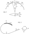
- FIG. 1 illustrates the forces that act when a yarn 1 is deflected. So that the yarn moves around the deflection radius r, for each piece of yarn, for example the piece of yarn between points A and B, must be included the mass m and the length 1, a corresponding centripetal force K z are applied.
- This centripetal force can be broken down into the two force components K SV and K SR , which act in the opposite direction in the yarn movement direction and the yarn movement direction, which act from the adjacent yarn pieces on the yarn piece under consideration and tension the yarn piece. From the physical conditions for the centripetal force it follows:
- (m / l) x v2 where m / l is the mass of the yarn per unit length, v is the yarn speed.
- Figure 2 shows the inventive method schematically.
- the yarn plug 1.1 is pushed at the constant speed v 1 in the direction indicated by the arrow v 1, the yarn 1.2 is drawn off in a different direction at the constant speed v 2, which is greater than v 1.
- the change in direction necessitates a deflection which is stable under the conditions specified in connection with FIG. 1 without mechanical guidance.
- Forces 1.2 acting forces also have a dissolving and stretching effect.
- the speeds v1 and v2 must be set so that the deflection is stable and that the acting forces are sufficient to dissolve the plug and stretch the yarn to the desired extent.
- the deflection radius will be set depending on the selected speeds, the available free yarn length and the arrangement of the system components.
- the balance is mainly dependent on the elastic and plastic properties of plug 1.1 and yarn 1.2, the two speeds v1 and v2 and the system-related deflection angle ⁇ .
- a certain curve shape of the plug-yarn loop will correspond to each balance. In the state of equilibrium, the plug-yarn loop is so stable that it does not require any mechanical backdrop to support it.
- the braking force on the yarn can be increased rsp. are weakened by any forces which additionally act on the yarn in such a way that they can be broken down into components in such a way that a component counteracts the direction of the yarn movement, that is to say acts as a braking force, rsp. acts in the direction of yarn movement, thus weakening the braking effect.
- forces which additionally act on the yarn in such a way that they can be broken down into components in such a way that a component counteracts the direction of the yarn movement, that is to say acts as a braking force, rsp. acts in the direction of yarn movement, thus weakening the braking effect.
- gravity or the frictional force on a flowing or standing medium can be used in this way.
- FIG. 3a shows an embodiment of the device according to the invention.
- the plug 1.1 which emerges from any texturing device 4, be it a texturing nozzle or a stuffer box, is applied in points C to a sieve drum or perforated roller 2 rotating at a constant surface speed v 1. Air is sucked into the screening drum 2, which simultaneously holds and cools the plug 1.1 on the drum surface.
- the plug 1.1 moves with the surface of the drum and, when it reaches the point D 1 rsp. D2 has reached, by a corresponding chicane or by closing the perforation so that it is no longer held by the negative pressure in the drum, detached from the drum surface.
- the yarn 1.2 is drawn off from the take-off spool 3 at the speed v 2.
- the cooling angle ⁇ ( ⁇ 1 rsp. ⁇ 2) changes. This mainly changes the deflection angle ⁇ ( ⁇ 1 or ⁇ 2), which affects the braking effect of the arrangement and thus the yarn tension in front of the take-off spool. In addition, such a change also changes the cooling time of the plug, which will have an impact due to the changed elastic and plastic properties of the plug and the yarn.
- the cooling angle ⁇ is well suited as a variation parameter for the stretching process.
- the cooling angle ⁇ can be varied by displacing the baffle which releases the plug from the drum, or by displacing the means which are provided for closing the perforation inside the drum.
- the arrangement shown in FIG. 3a for the stopper removal according to the invention can be changed by changing the relative positions of the screening drum 2 the take-off spool 3 are changed in such a way that gravity is increasingly included in the braking process during the deflection.
- Such an arrangement is shown in FIG. 3b.
- the plug 1.1 is pushed upwards by a corresponding arrangement of the detachment point D, by its kinetic energy, and changes its direction towards the bottom at a point E, which is dependent on the plug speed, the plug weight and the weight of the piece of plug hanging down. From this movement, it is deflected upward again by the correspondingly arranged take-off spool in the area of point F.
- the upward deflection as described in connection with the method according to the invention, has a braking effect on the stopper.
- the force of gravity at the deflection point F also has a braking effect and increases the braking effect, which results in a higher yarn tension.
- Variants of the two devices according to the invention shown in FIGS. 3a and 3b consist in that additional means are attached, for example with which air is blown against the deflection point, specifically from its concave side in order to increase the braking force, from the convex side to reduce the braking effect.
- additional means for example with which air is blown against the deflection point, specifically from its concave side in order to increase the braking force, from the convex side to reduce the braking effect.
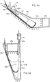
- FIGS. 4a and 4b show exemplary embodiments of the device according to the invention, in which no rotating sieve drum is used to cool the yarn plug.
- the plug 1.1 is conveyed through an inlet opening 40 into a channel-shaped, ventilated housing 41, in which it is driven downward by gravity emotional. In this housing, it is deflected by the force and withdrawal direction of the take-off spool 3 and is withdrawn accelerated through the outlet opening 42.
- FIG. 4a shows a corresponding housing 41a into which the plug 1.1 is inserted via the inclined guide groove 43a provided with holes.
- a deflection space 44a adjoins the guide trough 43a with a horizontal bottom, likewise provided with holes, in which the plug 1.1 is pulled off towards the top and against the direction of its insertion and is simultaneously dissolved.
- the exit opening 42a is located just above the entry opening 40a.
- An exhaust air duct 45a adjoins the deflection space 44a on the side opposite the inlet and outlet opening and is connected to the deflection space 44a by holes.
- Air is actively sucked out of the housing 41a through the exhaust air duct 44a and outside air is sucked in through the holes in the guide trough 43a and the deflection space 44a and through the inlet and outlet openings (40a / 42a).
- the resulting air flow in the housing 41a (indicated by arrows in the figure) runs in the inlet opening 40a in the yarn transport direction, in the outlet opening 42a against the yarn movement direction, so that it acts as a brake on the yarn 1.2.
- the air flow has a more or less braking effect on the plug and yarn.
- Figure 4b shows a device similar to Figure 4a.
- the housing 41b has a much steeper guide groove 43b, so that the deflection loop has a hanging position.
- gravity acts as a brake, but the exhaust duct 45b is arranged between the inlet opening 40b and the outlet opening 42b in such a way that the air flow through the housing 41b counteracts the braking.
- FIG. 5 shows how any of the embodiments of the device for plug dissolution according to the invention can be integrated into a complete arrangement for producing textured yarns.
- the arrangement is shown in FIG. 5a, while FIG. 5b shows a corresponding arrangement according to the prior art and is used for comparison.
- the arrangement comprises an entry zone between points P and Q, in which the fibrils emerging from the spinnerets are combined to form a yarn and the yarn is pre-stretched.
- the texturing zone follows between points Q and R, in which the yarn is textured and the plug formed during texturing is dissolved. This is followed by the draw-off zone between points R and T, in which the yarn is stretched, swirled and wound up.
- the point R between the texturing zone and the draw-off zone is not shown in FIG.
Landscapes
- Engineering & Computer Science (AREA)
- Textile Engineering (AREA)
- Mechanical Engineering (AREA)
- Yarns And Mechanical Finishing Of Yarns Or Ropes (AREA)
- Spinning Methods And Devices For Manufacturing Artificial Fibers (AREA)
Applications Claiming Priority (2)
| Application Number | Priority Date | Filing Date | Title |
|---|---|---|---|
| CH377590 | 1990-11-29 | ||
| CH3775/90 | 1990-11-29 |
Publications (2)
| Publication Number | Publication Date |
|---|---|
| EP0488939A1 true EP0488939A1 (fr) | 1992-06-03 |
| EP0488939B1 EP0488939B1 (fr) | 1995-02-22 |
Family
ID=4263222
Family Applications (1)
| Application Number | Title | Priority Date | Filing Date |
|---|---|---|---|
| EP91810691A Expired - Lifetime EP0488939B1 (fr) | 1990-11-29 | 1991-08-30 | Méthode et dispositif pour le désentrelacement d'un tampon de fil après la texturation |
Country Status (4)
| Country | Link |
|---|---|
| US (1) | US5339502A (fr) |
| EP (1) | EP0488939B1 (fr) |
| JP (1) | JPH04263635A (fr) |
| DE (1) | DE59104693D1 (fr) |
Cited By (2)
| Publication number | Priority date | Publication date | Assignee | Title |
|---|---|---|---|---|
| EP1607500A1 (fr) | 2004-06-16 | 2005-12-21 | Maschinenfabrik Rieter Ag | Dispositif de texturation avec démêlage étirage et freinage |
| WO2006048035A1 (fr) * | 2004-11-05 | 2006-05-11 | Saurer Gmbh & Co. Kg | Procédé et un dispositif pour filer et texturer un fil synthétique |
Families Citing this family (5)
| Publication number | Priority date | Publication date | Assignee | Title |
|---|---|---|---|---|
| CH689040B5 (de) * | 1992-11-19 | 1999-02-26 | Rieter Ag Maschf | Verfahren und Vorrichtung zum Texturieren von thermoplastischen Fäden. |
| DE59908662D1 (de) * | 1998-09-10 | 2004-04-01 | Barmag Barmer Maschf | Texturiermaschine zum texturieren und aufwickeln eines fadens |
| US6528950B2 (en) * | 2000-04-06 | 2003-03-04 | Semiconductor Energy Laboratory Co., Ltd. | Electronic device and driving method |
| DE10202788A1 (de) * | 2002-01-25 | 2003-07-31 | Rieter Ag Maschf | Texturieranlage und Texturierdüse hierfür |
| US20090246896A1 (en) * | 2007-07-19 | 2009-10-01 | Melissa Kreger | Method and apparatus for improved printed cathodes for organic electronic devices |
Citations (2)
| Publication number | Priority date | Publication date | Assignee | Title |
|---|---|---|---|---|
| CH618561GA3 (en) * | 1977-03-05 | 1980-08-15 | Method for transporting away textured yarns | |
| DE4014639A1 (de) * | 1989-05-18 | 1990-11-22 | Barmag Barmer Maschf | Verfahren zum stauchkraeuseln eines mehrkomponentenfadens |
Family Cites Families (11)
| Publication number | Priority date | Publication date | Assignee | Title |
|---|---|---|---|---|
| GB1132984A (en) * | 1965-04-01 | 1968-11-06 | Courtaulds Ltd | Process and apparatus for opening tow |
| US4019228A (en) * | 1970-03-05 | 1977-04-26 | Mitsubishi Rayon Co., Ltd. | Crimping apparatus |
| US3861133A (en) * | 1971-12-22 | 1975-01-21 | Du Pont | Production of highly crimped polyester yarn |
| US3885278A (en) * | 1973-05-11 | 1975-05-27 | Whitaker Co Fred | Apparatus for texturing yarn |
| US4027466A (en) * | 1975-06-17 | 1977-06-07 | Heberlein Maschinenfabrik Ag | Process for continuously treating thermoplastic yarns |
| JPS54151653A (en) * | 1978-05-16 | 1979-11-29 | Teijin Ltd | Crimping method and apparatus of yarn |
| US4309801A (en) * | 1979-06-28 | 1982-01-12 | Chevron Research | Texturizing process |
| US4319388A (en) * | 1980-06-11 | 1982-03-16 | E. I. Du Pont De Nemours And Company | Treatment for bulked continuous filament yarns |
| JPS607049A (ja) * | 1983-06-24 | 1985-01-14 | Hitachi Ltd | 電位測定装置 |
| GB8701046D0 (en) * | 1987-01-16 | 1987-02-18 | Mackie & Sons Ltd J | Production of textured yarn |
| RU2041981C1 (ru) * | 1989-11-11 | 1995-08-20 | Бармаг АГ | Фильера для текстурирования синтетической нити |
-
1991
- 1991-08-30 EP EP91810691A patent/EP0488939B1/fr not_active Expired - Lifetime
- 1991-08-30 DE DE59104693T patent/DE59104693D1/de not_active Expired - Fee Related
- 1991-10-05 JP JP3258195A patent/JPH04263635A/ja active Pending
- 1991-11-27 US US07/800,637 patent/US5339502A/en not_active Expired - Fee Related
Patent Citations (2)
| Publication number | Priority date | Publication date | Assignee | Title |
|---|---|---|---|---|
| CH618561GA3 (en) * | 1977-03-05 | 1980-08-15 | Method for transporting away textured yarns | |
| DE4014639A1 (de) * | 1989-05-18 | 1990-11-22 | Barmag Barmer Maschf | Verfahren zum stauchkraeuseln eines mehrkomponentenfadens |
Cited By (2)
| Publication number | Priority date | Publication date | Assignee | Title |
|---|---|---|---|---|
| EP1607500A1 (fr) | 2004-06-16 | 2005-12-21 | Maschinenfabrik Rieter Ag | Dispositif de texturation avec démêlage étirage et freinage |
| WO2006048035A1 (fr) * | 2004-11-05 | 2006-05-11 | Saurer Gmbh & Co. Kg | Procédé et un dispositif pour filer et texturer un fil synthétique |
Also Published As
| Publication number | Publication date |
|---|---|
| DE59104693D1 (de) | 1995-03-30 |
| US5339502A (en) | 1994-08-23 |
| JPH04263635A (ja) | 1992-09-18 |
| EP0488939B1 (fr) | 1995-02-22 |
Similar Documents
| Publication | Publication Date | Title |
|---|---|---|
| DE19605675C5 (de) | Verfahren zum aerodynamischen Texturieren sowie Texturierdüse | |
| EP0488939B1 (fr) | Méthode et dispositif pour le désentrelacement d'un tampon de fil après la texturation | |
| EP0682720A1 (fr) | Procede de filature a chaud de filaments | |
| CH679679A5 (fr) | ||
| EP2881502B1 (fr) | Dispositif de traitement continu d'un produit en forme de fil | |
| DE2206907C2 (de) | Verfahren und Vorrichtung zum Kräuseln eines thermoplastischen Mehrfadengarnes | |
| DE2618406B2 (de) | Verfahren zum Herstellen vororientierter Füamentgarne aus thermoplastischen Polymeren | |
| CH682825A5 (de) | Vorrichtung zur Herstellung von Spinngarn. | |
| DE4220915A1 (de) | Verfahren und Vorrichtung zur Herstellung synthetischer Endlosfilamente | |
| DE2255486C3 (de) | Fadenspeichervorrichtung | |
| EP0175862B1 (fr) | Procédé et dispositif pour la production de fil | |
| DE1900098A1 (de) | Vorrichtung und Verfahren zum Falschdrallen von Textilfaeden | |
| DE2217109C3 (de) | Verfahren und Vorrichtung zum Kräuseln von Fäden und Garnen | |
| DE3602968C2 (fr) | ||
| DE2632082C2 (de) | Verfahren zur thermischen Nachbehandlung von gekräuselten thermoplastischen, multifilen Chemiefäden und Vorrichtung zum Durchführen des Verfahrens | |
| EP1173634B1 (fr) | Systeme de refroidissement pour fils de filaments continus | |
| EP0434601A1 (fr) | Procédé et dispositif pour la fabrication d'un fil non-retordu, composé d'au moins deux faisceaux de filaments ayant une disposition relative l'un par rapport à l'autre, constante | |
| DE1435388A1 (de) | Verfahren und Vorrichtung zur Herstellung gedrillter Faeden | |
| DE10061503B4 (de) | Bremsanordnung für eine Anzahl von Fäden oder Garnen, die in eine Textilmaschine eingeführt oder einer Textilmaschine zugeführt werden können | |
| CH468482A (de) | Vorrichtung zur Verhinderung von Luftwirbelbildung im Spinnschacht | |
| CH650285A5 (de) | Verfahren und vorrichtung zum herstellen von garn durch verziehen und umwinden. | |
| DE3735752C2 (de) | Verfahren zur Herstellung von Glattgarn aus Polyamid oder Polyester | |
| DE2049594A1 (de) | Verfahren und Vorrichtung zur Herstellung von Elemeirtarfadenvliesstoff | |
| CH683923A5 (de) | Streckkammeranordnung. | |
| CH699610B1 (de) | Anlage zur kontinuierlichen Herstellung von zwei oder mehr Fäden mit jeweils endlosen synthetischen Fasern. |
Legal Events
| Date | Code | Title | Description |
|---|---|---|---|
| PUAI | Public reference made under article 153(3) epc to a published international application that has entered the european phase |
Free format text: ORIGINAL CODE: 0009012 |
|
| AK | Designated contracting states |
Kind code of ref document: A1 Designated state(s): CH DE FR GB IT LI |
|
| 17P | Request for examination filed |
Effective date: 19921012 |
|
| 17Q | First examination report despatched |
Effective date: 19931227 |
|
| GRAA | (expected) grant |
Free format text: ORIGINAL CODE: 0009210 |
|
| AK | Designated contracting states |
Kind code of ref document: B1 Designated state(s): CH DE FR GB IT LI |
|
| REF | Corresponds to: |
Ref document number: 59104693 Country of ref document: DE Date of ref document: 19950330 |
|
| GBT | Gb: translation of ep patent filed (gb section 77(6)(a)/1977) |
Effective date: 19950323 |
|
| ITF | It: translation for a ep patent filed | ||
| ET | Fr: translation filed | ||
| PG25 | Lapsed in a contracting state [announced via postgrant information from national office to epo] |
Ref country code: GB Effective date: 19950830 |
|
| PG25 | Lapsed in a contracting state [announced via postgrant information from national office to epo] |
Ref country code: LI Effective date: 19950831 Ref country code: CH Effective date: 19950831 |
|
| PLBE | No opposition filed within time limit |
Free format text: ORIGINAL CODE: 0009261 |
|
| STAA | Information on the status of an ep patent application or granted ep patent |
Free format text: STATUS: NO OPPOSITION FILED WITHIN TIME LIMIT |
|
| 26N | No opposition filed | ||
| REG | Reference to a national code |
Ref country code: CH Ref legal event code: PL |
|
| PG25 | Lapsed in a contracting state [announced via postgrant information from national office to epo] |
Ref country code: FR Effective date: 19960430 |
|
| GBPC | Gb: european patent ceased through non-payment of renewal fee |
Effective date: 19950830 |
|
| PG25 | Lapsed in a contracting state [announced via postgrant information from national office to epo] |
Ref country code: DE Effective date: 19960501 |
|
| REG | Reference to a national code |
Ref country code: FR Ref legal event code: ST |
|
| PG25 | Lapsed in a contracting state [announced via postgrant information from national office to epo] |
Ref country code: IT Free format text: LAPSE BECAUSE OF NON-PAYMENT OF DUE FEES;WARNING: LAPSES OF ITALIAN PATENTS WITH EFFECTIVE DATE BEFORE 2007 MAY HAVE OCCURRED AT ANY TIME BEFORE 2007. THE CORRECT EFFECTIVE DATE MAY BE DIFFERENT FROM THE ONE RECORDED. Effective date: 20050830 |