EP0489280B1 - Unité d'alimentation pour un respirateur - Google Patents
Unité d'alimentation pour un respirateur Download PDFInfo
- Publication number
- EP0489280B1 EP0489280B1 EP91119314A EP91119314A EP0489280B1 EP 0489280 B1 EP0489280 B1 EP 0489280B1 EP 91119314 A EP91119314 A EP 91119314A EP 91119314 A EP91119314 A EP 91119314A EP 0489280 B1 EP0489280 B1 EP 0489280B1
- Authority
- EP
- European Patent Office
- Prior art keywords
- piston
- cylinder
- bag
- membrane
- rolling
- Prior art date
- Legal status (The legal status is an assumption and is not a legal conclusion. Google has not performed a legal analysis and makes no representation as to the accuracy of the status listed.)
- Expired - Lifetime
Links
- 230000000241 respiratory effect Effects 0.000 title claims description 4
- 239000012528 membrane Substances 0.000 claims description 61
- 238000005096 rolling process Methods 0.000 claims description 24
- 210000002345 respiratory system Anatomy 0.000 claims 1
- 230000029058 respiratory gaseous exchange Effects 0.000 description 22
- 239000000853 adhesive Substances 0.000 description 11
- 230000001070 adhesive effect Effects 0.000 description 11
- 239000011248 coating agent Substances 0.000 description 6
- 238000000576 coating method Methods 0.000 description 6
- 238000009423 ventilation Methods 0.000 description 5
- 230000000694 effects Effects 0.000 description 2
- 230000003534 oscillatory effect Effects 0.000 description 2
- 230000015572 biosynthetic process Effects 0.000 description 1
- 238000010276 construction Methods 0.000 description 1
- 230000008878 coupling Effects 0.000 description 1
- 238000010168 coupling process Methods 0.000 description 1
- 238000005859 coupling reaction Methods 0.000 description 1
- 238000002474 experimental method Methods 0.000 description 1
- 238000004519 manufacturing process Methods 0.000 description 1
- 238000012806 monitoring device Methods 0.000 description 1
- 238000012544 monitoring process Methods 0.000 description 1
- 238000002360 preparation method Methods 0.000 description 1
- 238000007789 sealing Methods 0.000 description 1
- 238000000926 separation method Methods 0.000 description 1
- 230000001225 therapeutic effect Effects 0.000 description 1
Images
Classifications
-
- A—HUMAN NECESSITIES
- A61—MEDICAL OR VETERINARY SCIENCE; HYGIENE
- A61M—DEVICES FOR INTRODUCING MEDIA INTO, OR ONTO, THE BODY; DEVICES FOR TRANSDUCING BODY MEDIA OR FOR TAKING MEDIA FROM THE BODY; DEVICES FOR PRODUCING OR ENDING SLEEP OR STUPOR
- A61M16/00—Devices for influencing the respiratory system of patients by gas treatment, e.g. ventilators; Tracheal tubes
- A61M16/0057—Pumps therefor
- A61M16/0072—Tidal volume piston pumps
-
- A—HUMAN NECESSITIES
- A61—MEDICAL OR VETERINARY SCIENCE; HYGIENE
- A61M—DEVICES FOR INTRODUCING MEDIA INTO, OR ONTO, THE BODY; DEVICES FOR TRANSDUCING BODY MEDIA OR FOR TAKING MEDIA FROM THE BODY; DEVICES FOR PRODUCING OR ENDING SLEEP OR STUPOR
- A61M16/00—Devices for influencing the respiratory system of patients by gas treatment, e.g. ventilators; Tracheal tubes
- A61M16/0057—Pumps therefor
- A61M16/006—Tidal volume membrane pumps
Definitions
- the invention relates to a delivery unit for a respirator with a piston-cylinder unit as a drive device, in which a piston is sealed against a cylinder by a cup-shaped bag roll membrane and a roll membrane arranged symmetrically to the bag roll membrane, with a working chamber enclosed by the bag roll membrane, which has a working chamber on one end face of the cylinder attached connecting plate as a fixed chamber part and an end plate of the piston as a movable chamber part, the bag roll membrane with its bottom surface abutting the end plate of the piston and with its open end on the end face of the cylinder, with an inner space that moves with the piston movement between the roll membranes , which is enclosed on the one hand by a piston wall of the piston and a cylinder wall of the cylinder and on the other hand by folds of the rolling membranes and is set to a pressure which is lower than that of the working chamber
- a delivery unit for a respirator is known from US Pat. No. 4,010,761, which has a piston-cylinder unit as the drive device with two roller membranes arranged symmetrically to one another for sealing the piston against the cylinder.
- One of the roll membranes is designed as a pot-shaped bag roll membrane and is attached to one of the end faces of the cylinder with a connecting plate.
- the bag roll membrane separates a volume-adjustable working chamber from the cylinder contents.
- the bottom of the bag roll membrane lies on the piston of the piston-cylinder unit which executes the breathing gas delivery stroke.
- a disadvantage of the known conveyor unit is that the bag roll membrane and the connecting plate have to be removed individually from the drive device in order to clean parts carrying breathing gas.
- a delivery unit for a respirator with a piston-cylinder unit as a drive device has become known from DE-A1 38 17 091.
- the piston guided in a cylinder is sealed off from the cylinder by a pair of roller membranes arranged symmetrically to one another, which divides the cylinder contents into a prechamber and a working chamber.
- the interior enclosed by the roll membranes is kept under a pressure which is higher than the pressure in both the antechamber and in the working chamber and on the concave inner sides of the folds the roll membrane is in contact, which ensures that the folds are formed consistently and lie flat against the walls of the piston and cylinder throughout the breath. If, on the other hand, the convex outer sides of the folds face each other, the interior is kept at a negative pressure in relation to the adjacent chambers. It is possible to check the tightness of the rolling membrane during operation by monitoring the pressure in the interior, so that leaks can be recognized immediately.
- the piston is moved in an oscillatory manner by a drive unit and the breathing gas displaced from the working chamber during the working stroke is conveyed to a breathing system via a connecting piece attached to the connecting plate.
- Accurate dosing of both small and large tidal volumes is possible because the delivery unit has a low compliance due to the rigid piston and cylinder wall and the total gas volume from the working chamber is expressed in the top dead center of the piston.
- the compliance of the rolling diaphragms is of minor importance, since it is only effective in the edge area in the gap between the piston and the cylinder.
- a ventilator is known with a volume-adjustable chamber designed as a bellows, which is set in oscillatory motion by a drive means, and can be coupled in a rack-like manner with the ventilator.
- the bellows is connected to the movable part of the drive via fastening means, which are designed here as magnetic couplings. Due to the insert-like construction, the parts that come into contact with the breathing gas, e.g. the bellows, removed and sterilized separately from the ventilator.
- the invention has for its object to improve a delivery unit for a respirator in such a way that with precise dosing of both large and small breathing volumes with the same working chamber volume, the breathing gas-carrying parts can be easily inserted into and removed from the drive device.
- connection plate has a fastening means into which the open end of the bag roll membrane can be buttoned, so that the bag roll membrane, together with the connection plate, can be inserted into the cylinder in the manner of a insert.
- a rolling membrane in the piston-cylinder unit with two rolling membranes, a rolling membrane is designed as a pot-shaped bag rolling membrane connected to the connector, which can be inserted as a working chamber into the drive device and the Interior space between the roll membranes is connected to a vacuum source and is kept at a pressure level below the pressure in the working chamber. Due to the negative pressure between the interior and the working chamber, the bag roll membrane lies against the cylinder wall and the end plate of the piston, while at the same time the folds form between the piston wall and the cylinder wall.
- the vacuum in the interior is reduced to the adhesive pressure in order to attach the bottom surface of the bag roll membrane to the end plate of the piston.
- the adhesive pressure depends on the diameter of the piston and the cylinder and the volume of the breathing gas conveyed by the bag roll membrane. Experiments have shown that for the practice-relevant respiratory stroke volumes the adhesive pressure is about 150 millibars below the average pressure prevailing in the working chamber.
- the attachment of the bottom surface of the bag roll membrane on the face plate of the piston via the adhesive pressure in the Interior also causes the bag roll membrane to be automatically centered within the cylinder during the first piston stroke. If, for example, the bag roll membrane was inserted canted into the cylinder, it initially lies against the cylinder wall and the end plate of the piston under the effect of the adhesive pressure.
- the piston is moved to the bottom dead center, the folds form between the piston and cylinder walls, causing the bag roll membrane to be pulled into the working position.
- an adhesive coating between the bottom surface of the bag roll membrane and the end plate of the piston as the fastening means.
- the adhesive coating ensures adhesion regardless of the pressure in the interior. If, for example, a fault occurs within the vacuum source so that no negative pressure can be generated in the interior, ventilation with the piston-cylinder unit is nevertheless possible due to the adhesive coating.
- the adhesive coating can be applied over the entire surface of the bottom surface and the end plate or in segments as a punctiform or circular coating.
- the upper end of the bag roll membrane is expediently buttoned into a projection of the connection plate.
- connection plate design the connection plate as a breathing system which, together with the bag roll membrane, can be inserted into the cylinder as a self-contained working chamber.
- the breathing gas-carrying parts of the ventilator can be inserted into or removed from the cylinder as a compact module.
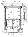
- a cylinder (1) is shown, the end faces of which are closed by a base plate (2) and a connecting plate (3).
- a piston (4) is received on a piston rod (5) guided in an axial bearing (6), which is connected to a drive device (7).
- the piston wall (28) is sealed off from the cylinder (1) with a rolling membrane (9) and a bag rolling membrane (8), the open end (30) of the bag rolling membrane (8) being buttoned into a projection (33) of the connecting plate (3) and the rolling membrane (9) is clamped between the cylinder (1) and the base plate (2).
- the projection (33) of the connection plate (3) sits by the folded bag roll membrane (8) sealingly on one end of the cylinder (1).
- the line (13) opens into a distributor (17), which is designed as a longitudinal groove in the cylinder wall (29) and serves to connect the interior (12) and the line (13) in every position of the piston (4). to manufacture.
- the roller membranes (8, 9) divide the interior of the cylinder (1) into a prechamber (18) which is connected to the environment via a passage (19), and into a working chamber (20) in which the ventilation pressure generated by the stroke movement of the piston (4) prevails.
- the piston (4) has on its side facing the working chamber (20) an end plate (21) against which the bottom surface (31) of the bag roll membrane (8) bears.
- the breathing gas displaced during the working stroke can flow through the connection piece (22) attached to the connection plate (3) to a breathing system (25) of a ventilator (not shown).
- the breathing system (25) has connections (26, 27) for an inhalation line and exhalation line, not shown, via which the breathing gas is supplied.
- a pressure measuring device (15) is connected to the line (13), the measuring signal of which is passed on to a control unit (23) which at the same time records the setpoint value supplied by the vacuum source (14).
- a display unit (24) shows the current state of the vacuum in the interior (12) and emits any necessary warning signals.
- the conveying device is started up in such a way that the breathing system (25) with the connecting plate (3) and the bag rolling membrane (8) is placed on the cylinder (1) and the vacuum source (14) is switched on. Due to the negative pressure which arises in the interior (12), the bag roll membrane (8) lies against the cylinder wall (29) and the bottom surface (31) of the bag roll membrane (8) lies against the end plate (21) of the piston (4).
- the connecting plate (3) is also pressed against the end face of the cylinder (1) by the negative pressure, the bag roll membrane (8) located at the separation point between the connecting plate (3) and the cylinder (1) provides a gas-tight seal.
- the fold (11) of the bag roll membrane is centered between the piston wall (28) and the cylinder wall (29) under the effect of the negative pressure, so that a correct rolling of the folds (10, 11) is guaranteed in the subsequent piston strokes.
- a vacuum or adhesive pressure of approximately 150 millibars is required for a uniform formation of folds in the rolling membranes (8, 9) and firm adherence of the bottom surface (31) to the end plate (21).
- a punctiform adhesive coating (32) is provided on the contact surface.
Landscapes
- Health & Medical Sciences (AREA)
- Emergency Medicine (AREA)
- Pulmonology (AREA)
- Engineering & Computer Science (AREA)
- Anesthesiology (AREA)
- Biomedical Technology (AREA)
- Heart & Thoracic Surgery (AREA)
- Hematology (AREA)
- Life Sciences & Earth Sciences (AREA)
- Animal Behavior & Ethology (AREA)
- General Health & Medical Sciences (AREA)
- Public Health (AREA)
- Veterinary Medicine (AREA)
- Respiratory Apparatuses And Protective Means (AREA)
Claims (3)
- Unité d'alimentation destinée à un appareil d'assistance respiratoire, pourvue d'une unité piston/cylindre servant de dispositif d'entraînement, dans laquelle un piston (4) est rendu étanche vis-à-vis d'un cylindre (1) par une membrane roulée formant sac (8) en forme de creuset et par une membrane roulée (9) disposée de façon symétrique par rapport à la membrane roulée formant sac (8), pourvue d'une chambre de travail (20) entourée par la membrane roulée formant sac (8), qui présente une plaque de raccordement (3) disposée sur une face frontale du cylindre (1) et servant de partie de chambre fixe, ainsi qu'une plaque frontale (21) du piston (4) servant de partie de chambre mobile, la membrane roulée formant sac (8) venant s'appliquer, par sa surface de fond (31), sur la plaque frontale (21) du piston (4) et, par son extrémité ouverte (30), sur la face frontale du cylindre (1), pourvue d'un espace intérieur (12) suivant le déplacement du piston et existant entre les membranes roulées (8, 9), qui est entouré, d'une part, par une paroi (28) du piston (4) et une paroi (29) du cylindre (1) et, d'autre part, par des plis (10, 11) des membranes roulées (8, 9), et qui est mis à une pression abaissée par rapport à celle de la chambre de travail (20), caractérisée en ce que la plaque de raccordement (3) présente un moyen de fixation (33), dans lequel l'extrémité ouverte (30) de la membrane roulée formant sac (8) est susceptible de s'insérer, de telle sorte que la membrane roulée formant sac (8), avec la plaque de raccordement (3), puisse être introduite dans le cylindre (1) en y étant enfilée.
- Unité d'alimentation selon la revendication 1, caractérisée en ce que le moyen de fixation est une saillie (33).
- Unité d'alimentation selon la revendication 1 ou 2, caractérisée en ce que la plaque de raccordement est conformée en système respiratoire (25).
Applications Claiming Priority (2)
| Application Number | Priority Date | Filing Date | Title |
|---|---|---|---|
| DE4038499A DE4038499A1 (de) | 1990-12-03 | 1990-12-03 | Foerdereinheit fuer ein beatmungsgeraet |
| DE4038499 | 1990-12-03 |
Publications (2)
| Publication Number | Publication Date |
|---|---|
| EP0489280A1 EP0489280A1 (fr) | 1992-06-10 |
| EP0489280B1 true EP0489280B1 (fr) | 1995-07-19 |
Family
ID=6419477
Family Applications (1)
| Application Number | Title | Priority Date | Filing Date |
|---|---|---|---|
| EP91119314A Expired - Lifetime EP0489280B1 (fr) | 1990-12-03 | 1991-11-13 | Unité d'alimentation pour un respirateur |
Country Status (3)
| Country | Link |
|---|---|
| EP (1) | EP0489280B1 (fr) |
| JP (1) | JPH082373B2 (fr) |
| DE (2) | DE4038499A1 (fr) |
Families Citing this family (3)
| Publication number | Priority date | Publication date | Assignee | Title |
|---|---|---|---|---|
| US5657751A (en) * | 1993-07-23 | 1997-08-19 | Karr, Jr.; Michael A. | Cardiopulmonary resuscitation unit |
| WO1998045488A1 (fr) * | 1997-04-04 | 1998-10-15 | Valery Ivanovich Chernyshev | Procede d'extraction par sorption de metaux du groupe des platines sur les surfaces de pieces et appareillage |
| US9427540B2 (en) * | 2005-11-08 | 2016-08-30 | Carefusion 207, Inc. | High frequency oscillator ventilator |
Family Cites Families (17)
| Publication number | Priority date | Publication date | Assignee | Title |
|---|---|---|---|---|
| FR1588144A (fr) * | 1968-10-31 | 1970-04-03 | ||
| DE2064848A1 (de) * | 1970-01-02 | 1971-07-15 | Pye Ltd., Cambridge (Grossbritannien) | Medizinischer Atmungsapparat |
| US3932066A (en) * | 1973-10-02 | 1976-01-13 | Chemetron Corporation | Breathing gas delivery cylinder for respirators |
| US3905362A (en) * | 1973-10-02 | 1975-09-16 | Chemetron Corp | Volume-rate respirator system and method |
| SE388127B (sv) * | 1975-04-30 | 1976-09-27 | Cameco Ab | Respiratorsystem |
| CH599786A5 (fr) * | 1975-10-24 | 1978-05-31 | Hoffmann La Roche | |
| US4010761A (en) * | 1975-11-10 | 1977-03-08 | Puritan-Bennett Corporation | Delivery means for use in volume-controlled respiration apparatus |
| JPS55118747A (en) * | 1979-03-05 | 1980-09-11 | Tokyo Shibaura Electric Co | Patient monitor device |
| US4832014A (en) * | 1985-10-02 | 1989-05-23 | Perkins Warren E | Method and means for dispensing two respirating gases by effecting a known displacement |
| GB8704104D0 (en) * | 1987-02-21 | 1987-03-25 | Manitoba University Of | Respiratory system load apparatus |
| DE3817092A1 (de) * | 1988-05-19 | 1989-11-30 | Draegerwerk Ag | Foerdervorrichtung zur versorgung eines beatmungsgeraetes mit atemgas |
| DE3817091A1 (de) * | 1988-05-19 | 1989-11-30 | Draegerwerk Ag | Kolben-zylindereinheit als foerdervorrichtung in einem beatmungsgeraet |
| JPH0246259U (fr) * | 1988-09-20 | 1990-03-29 | ||
| JPH02107223A (ja) * | 1988-10-17 | 1990-04-19 | Tokyo Shokai:Kk | 医療情報処理装置 |
| JPH0386147A (ja) * | 1989-08-31 | 1991-04-11 | Toshiba Corp | 処方データ展開処理システム |
| JPH0465771A (ja) * | 1990-07-06 | 1992-03-02 | Toshiba Joho Kiki Kk | 医用データ処理システム |
| JPH0540768A (ja) * | 1991-08-05 | 1993-02-19 | Hokuriku Nippon Denki Software Kk | 処方データ入力装置 |
-
1990
- 1990-12-03 DE DE4038499A patent/DE4038499A1/de not_active Withdrawn
-
1991
- 1991-11-13 EP EP91119314A patent/EP0489280B1/fr not_active Expired - Lifetime
- 1991-11-13 DE DE59106030T patent/DE59106030D1/de not_active Expired - Fee Related
- 1991-12-03 JP JP3318878A patent/JPH082373B2/ja not_active Expired - Lifetime
Also Published As
| Publication number | Publication date |
|---|---|
| DE59106030D1 (de) | 1995-08-24 |
| DE4038499A1 (de) | 1992-06-04 |
| JPH082373B2 (ja) | 1996-01-17 |
| EP0489280A1 (fr) | 1992-06-10 |
| JPH07517A (ja) | 1995-01-06 |
Similar Documents
| Publication | Publication Date | Title |
|---|---|---|
| DE2334626B2 (de) | Drainageapparat zum Absaugen der Pleurahöhle | |
| EP0182248B1 (fr) | Dispositif d'aspiration de sécrétions d'une plaie | |
| DE60032008T3 (de) | Saugbeutelanordnung | |
| EP1003584B1 (fr) | Tube endotracheal ou de tracheotomie | |
| DE19508512A1 (de) | Saugkatheter | |
| DE112009003558T5 (de) | Pumpe und Ausatmungsventilsteuerung für Respiratorgerät | |
| EP1527791A2 (fr) | Dispositif de succion de fluides | |
| DE2652197A1 (de) | Druckpumpe fuer eine infusionsvorrichtung | |
| DE69822531T2 (de) | Volumetrische Pumpe mit einer Zweirichtungsdichtung | |
| EP0191071A1 (fr) | Dispositif de pompage de liquides tres sensibles a des contraintes mecaniques. | |
| DE2750350C2 (fr) | ||
| EP2021677A1 (fr) | Écouvillon avec effet d'étanchéité amélioré | |
| EP2379211B1 (fr) | Dispositif mélangeur avec indication de changement de pression | |
| DE3331595A1 (de) | Pumpe und kassette fuer diese | |
| EP0489280B1 (fr) | Unité d'alimentation pour un respirateur | |
| DE3817091C2 (fr) | ||
| EP4275730B1 (fr) | Filtre de gaz respiratoire remplaçable | |
| DE4009468A1 (de) | Beatmungstubus | |
| EP0355456A2 (fr) | Dispositif pour le traitement du sang avec un gaz | |
| DE202012007884U1 (de) | Einweg-Ventileinrichtung | |
| DE2429541C3 (de) | Anästhesie-Beatmungsvorrichtung mit einer auf spontane Atemversuche ansprechenden Steuermembran | |
| DE2822030A1 (de) | Hubpumpe fuer gase, insbesondere fuer ein beatmungsgeraet | |
| EP0250853B1 (fr) | Dispositif de massage du coeur et de respiration | |
| DE2347429B2 (de) | Sauger aus elastischem Material | |
| WO2020043817A1 (fr) | Dispositif de drainage et ensemble de drainage |
Legal Events
| Date | Code | Title | Description |
|---|---|---|---|
| PUAI | Public reference made under article 153(3) epc to a published international application that has entered the european phase |
Free format text: ORIGINAL CODE: 0009012 |
|
| AK | Designated contracting states |
Kind code of ref document: A1 Designated state(s): DE FR GB |
|
| 17P | Request for examination filed |
Effective date: 19921107 |
|
| 17Q | First examination report despatched |
Effective date: 19940906 |
|
| GRAA | (expected) grant |
Free format text: ORIGINAL CODE: 0009210 |
|
| AK | Designated contracting states |
Kind code of ref document: B1 Designated state(s): DE FR GB |
|
| REF | Corresponds to: |
Ref document number: 59106030 Country of ref document: DE Date of ref document: 19950824 |
|
| ET | Fr: translation filed | ||
| GBT | Gb: translation of ep patent filed (gb section 77(6)(a)/1977) |
Effective date: 19950921 |
|
| PLBE | No opposition filed within time limit |
Free format text: ORIGINAL CODE: 0009261 |
|
| STAA | Information on the status of an ep patent application or granted ep patent |
Free format text: STATUS: NO OPPOSITION FILED WITHIN TIME LIMIT |
|
| 26N | No opposition filed | ||
| PGFP | Annual fee paid to national office [announced via postgrant information from national office to epo] |
Ref country code: GB Payment date: 20011022 Year of fee payment: 11 |
|
| PGFP | Annual fee paid to national office [announced via postgrant information from national office to epo] |
Ref country code: FR Payment date: 20011122 Year of fee payment: 11 |
|
| PGFP | Annual fee paid to national office [announced via postgrant information from national office to epo] |
Ref country code: DE Payment date: 20011211 Year of fee payment: 11 |
|
| REG | Reference to a national code |
Ref country code: GB Ref legal event code: IF02 |
|
| PG25 | Lapsed in a contracting state [announced via postgrant information from national office to epo] |
Ref country code: GB Free format text: LAPSE BECAUSE OF NON-PAYMENT OF DUE FEES Effective date: 20021113 |
|
| PG25 | Lapsed in a contracting state [announced via postgrant information from national office to epo] |
Ref country code: DE Free format text: LAPSE BECAUSE OF NON-PAYMENT OF DUE FEES Effective date: 20030603 |
|
| GBPC | Gb: european patent ceased through non-payment of renewal fee | ||
| PG25 | Lapsed in a contracting state [announced via postgrant information from national office to epo] |
Ref country code: FR Free format text: LAPSE BECAUSE OF NON-PAYMENT OF DUE FEES Effective date: 20030731 |
|
| REG | Reference to a national code |
Ref country code: FR Ref legal event code: ST |