EP0489823B1 - Ausnehmerbacken - Google Patents
Ausnehmerbacken Download PDFInfo
- Publication number
- EP0489823B1 EP0489823B1 EP90913368A EP90913368A EP0489823B1 EP 0489823 B1 EP0489823 B1 EP 0489823B1 EP 90913368 A EP90913368 A EP 90913368A EP 90913368 A EP90913368 A EP 90913368A EP 0489823 B1 EP0489823 B1 EP 0489823B1
- Authority
- EP
- European Patent Office
- Prior art keywords
- insert
- takeout jaw
- holder
- takeout
- jaw assembly
- Prior art date
- Legal status (The legal status is an assumption and is not a legal conclusion. Google has not performed a legal analysis and makes no representation as to the accuracy of the status listed.)
- Revoked
Links
- 239000011521 glass Substances 0.000 claims description 21
- OKTJSMMVPCPJKN-UHFFFAOYSA-N Carbon Chemical compound [C] OKTJSMMVPCPJKN-UHFFFAOYSA-N 0.000 claims description 10
- 239000010439 graphite Substances 0.000 claims description 10
- 229910002804 graphite Inorganic materials 0.000 claims description 10
- 230000013011 mating Effects 0.000 claims description 5
- 229910000831 Steel Inorganic materials 0.000 claims description 2
- 239000010959 steel Substances 0.000 claims description 2
- 239000012634 fragment Substances 0.000 claims 1
- 239000000463 material Substances 0.000 abstract description 11
- 238000004519 manufacturing process Methods 0.000 description 7
- 238000003754 machining Methods 0.000 description 4
- 239000007769 metal material Substances 0.000 description 4
- 238000013461 design Methods 0.000 description 3
- 229910000906 Bronze Inorganic materials 0.000 description 2
- 238000000137 annealing Methods 0.000 description 2
- 239000010425 asbestos Substances 0.000 description 2
- 239000010974 bronze Substances 0.000 description 2
- KUNSUQLRTQLHQQ-UHFFFAOYSA-N copper tin Chemical compound [Cu].[Sn] KUNSUQLRTQLHQQ-UHFFFAOYSA-N 0.000 description 2
- 238000000034 method Methods 0.000 description 2
- 238000012986 modification Methods 0.000 description 2
- 230000004048 modification Effects 0.000 description 2
- 239000004033 plastic Substances 0.000 description 2
- 229920003023 plastic Polymers 0.000 description 2
- 238000012545 processing Methods 0.000 description 2
- 229910052895 riebeckite Inorganic materials 0.000 description 2
- 238000006748 scratching Methods 0.000 description 2
- 230000002393 scratching effect Effects 0.000 description 2
- 229920000049 Carbon (fiber) Polymers 0.000 description 1
- 238000005299 abrasion Methods 0.000 description 1
- 238000009825 accumulation Methods 0.000 description 1
- 229910045601 alloy Inorganic materials 0.000 description 1
- 239000000956 alloy Substances 0.000 description 1
- 230000000712 assembly Effects 0.000 description 1
- 238000000429 assembly Methods 0.000 description 1
- 230000015572 biosynthetic process Effects 0.000 description 1
- 239000004917 carbon fiber Substances 0.000 description 1
- 238000001816 cooling Methods 0.000 description 1
- 238000005520 cutting process Methods 0.000 description 1
- 230000003247 decreasing effect Effects 0.000 description 1
- 230000007613 environmental effect Effects 0.000 description 1
- 239000010419 fine particle Substances 0.000 description 1
- 238000005816 glass manufacturing process Methods 0.000 description 1
- 239000004519 grease Substances 0.000 description 1
- 230000003647 oxidation Effects 0.000 description 1
- 238000007254 oxidation reaction Methods 0.000 description 1
- 230000000717 retained effect Effects 0.000 description 1
- 230000035939 shock Effects 0.000 description 1
- 239000010935 stainless steel Substances 0.000 description 1
- 229910001220 stainless steel Inorganic materials 0.000 description 1
- 238000012546 transfer Methods 0.000 description 1
Images


Classifications
-
- C—CHEMISTRY; METALLURGY
- C03—GLASS; MINERAL OR SLAG WOOL
- C03B—MANUFACTURE, SHAPING, OR SUPPLEMENTARY PROCESSES
- C03B9/00—Blowing glass; Production of hollow glass articles
- C03B9/30—Details of blowing glass; Use of materials for the moulds
- C03B9/44—Means for discharging combined with glass-blowing machines, e.g. take-outs
- C03B9/447—Means for the removal of glass articles from the blow-mould, e.g. take-outs
-
- Y—GENERAL TAGGING OF NEW TECHNOLOGICAL DEVELOPMENTS; GENERAL TAGGING OF CROSS-SECTIONAL TECHNOLOGIES SPANNING OVER SEVERAL SECTIONS OF THE IPC; TECHNICAL SUBJECTS COVERED BY FORMER USPC CROSS-REFERENCE ART COLLECTIONS [XRACs] AND DIGESTS
- Y10—TECHNICAL SUBJECTS COVERED BY FORMER USPC
- Y10S—TECHNICAL SUBJECTS COVERED BY FORMER USPC CROSS-REFERENCE ART COLLECTIONS [XRACs] AND DIGESTS
- Y10S294/00—Handling: hand and hoist-line implements
- Y10S294/902—Gripping element
Definitions
- This invention relates to the field of glass-making.
- this invention relates to a fixture for use in a machine for lifting hot glass bottles from the molds in which they are formed.
- this invention relates to the combination of such a fixture and a non-metallic contact material especially adapted for use in the fixture.
- Hot glass especially when formed into various shapes in the manufacture of glass containers such as bottles, is susceptible to being damaged by contact with glass processing equipment.
- Most of the equipment with which hot glass comes in contact in the hot end process area during the manufacture of glass bottles is fabricated from metallic materials such as stainless steel and other alloys.
- non-metallic materials such as graphite, asbestos, plastics or carbon fibers.
- British Patent No. 2,126,211 (United Glass, PLC) relates to takeout tongs for use in the manufacture of glassware.
- the tong comprises a tong member (2) including a recess for receiving a jaw member.
- the jaw member is held in position by a pair of oval pins received in holes. This is typical of the prior art, and the jaw member is not held immovably within the tong member. Some movement is permitted by virtue of the connection.
- the jaw member becomes worn and a "rattling" or movement thereof within the recess increases with such use.
- the present invention provides takeout jaws which are designed to hold a piece of non-metallic contact material under spring tension in a manner such that the contact material does not move within the takeout jaws upon contacting a hot glass container. Because the contact material is held securely in position by spring tension, it is possible to lift the hot containers in a manner such that damage to the containers is minimized. Whereas takeout jaws which were previously used permitted a certain amount of movement of the inserts within the takeout jaws, the takeout jaws of the present invention do not permit such movement. Thus, the takeout jaws can be machined to close tolerances enabling the container lifting machine to operate as a precision machine. Because of the resulting gentle handling of the hot containers, it has become feasible to produce lighter weight glass containers and to increase the efficiency and hence the output.
- a takeout jaw of the present invention comprises a generally arcuate holder for an arcuate piece of non-metallic contact material, means at the middle of the arc formed by said arcuate holder for holding said arcuate piece immovably within said arcuate holder, and means integral with said holder for attaching the jaw to a support therefor.
- the takeout jaws of the present invention permit higher bottle yields and decrease the need for replacement of the contact material inserts.
- the takeout jaws of the present invention permit higher bottle yields, are economically producible in small quantities and are characterized by decreased need for replacement of inserts.
- the design of the takeout jaw of the present invention permits machining to close tolerances, thereby ensuring accurate and precise set up on the bottle forming machine.
- the precision machining of the takeout jaws combined with the tightness of the insert in the pocket of the jaw which contains the insert enables the takeout jaws to be accurately located in the bottle, in a reproducible manner, thereby reducing deformation of the bottle finish, that is, the top of the bottle, due to misalignment and consequently the number of bottles which must be scrapped.
- the inserts can be designed to contact the threaded finish only at the root and on the underside of the threads to further decrease the likelihood of damage.
- the machine fabrication of the takeout jaws of the present invention eliminates the high cost of tooling of the cast takeout jaws of the prior art and enables economic production even in relatively small quantities. Whereas the cast bronze takeout jaws of the prior art had to be manufactured in quantities of thousands of units to justify the high initial cost of tooling, the machined takeout jaws of the present invention can be manufactured economically in quantities as low as hundreds of units. Furthermore, the arcuate or semicircular shape of the takeout jaws of the present invention lends itself to being turned on a lathe.
- the number of parts required for the spring clip which retains the insert within a semicircular pocket in the takeout jaw is three, including spring, bolt and washer, for each takeout jaw compared to eight for the detent ball retainer, which requires two detent ball assemblies per jaw, each consisting of ball, leaf spring retainer, screw and washer.
- One of the major modes of insert failure is chipping of the surface of the insert. More precise mating of the insert with the bottle finish ensured by the close tolerance machining which is possible with the semicircular design of the insert of the present invention reduces the risk of chipping.
- the semicircular design of the pocket in which the insert is retained and the semicircular configuration of the insert ensure that the maximum surface contact between jaw and insert is realized. Since the insert contacts a large surface area of the pocket in the jaw and since the insert is held immovably within the pocket by a single insert retaining spring which is positioned at the center of the semicircular pocket, there can be no play between the insert and takeout jaw. Thus abrasion of the bottom surface of the insert caused by such play is eliminated. Precise alignment of the takeout jaws and bottles is thus maintained, reducing damage to bottles and increasing the life of the insert.
- Fig. 1 depicts the environment in which the takeout jaws of the present invention are used.
- the number 10 represents a series of the takeout jaws of the present invention, which are positioned above a series of hot bottles 12.
- Takeout jaws 10 are connected to a lifting arm 14.
- Bottles 12 have just been removed from a bottle forming mold 16 and are suspended just above air pad 18 by a cushion of air, the source of which is not shown.
- Hot bottles 12, which were red hot when lifted out of the mold by takeout jaws 10 are cooled upon air pad 18 and then transferred to a conveyor belt 20 for transport to an annealing furnace, not shown. Cooled bottles 22 are shown upon conveyor belt 20.
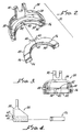
- a single takeout jaw 24 is shown along with a mating insert 26.
- Takeout jaw 24 has a semicircular body 28 and a yoke 30 for attachment to a lifting arm.
- Body 28 has a base 32 and a shelf 34 which form between them a semicircular pocket 36.
- Pocket 36 is open at the front and closed at the rear by semicircular back wall 38 of body 28 except for an opening 40 in the center of back wall 38.
- a center portion 42 is the lower surface of shelf 34 is cut out to provide clearance for a spring clip, not shown.
- Insert 26 is generally semicircular in form except for a lug 44 formed by cutting notches in the back wall 46 of insert 26.
- the upper surface 48 of insert 26 has a depression 50 with a hole 52 in the bottom thereof. Hole 52 is used for locating or fixturing purposes in machining insert 26 to the desired dimensions.
- the front surface 54 is generally semicircular except for two flat portions 56 at either end of the semicircle. If desired, front surface 54 can be threaded to provide a convenient means for contacting bottles having threaded finishes.
- Fig. 3 in addition to the features described with respect to Fig. 2, has a spring clip 58 shown in opening 40 at center portion 42.
- Fig. 4 shows the several horizontal surfaces in phantom and also shows that the insert is adapted to be positioned within the pocket in the takeout jaw and that the spring clip and depression in the insert are lined up to be engaged.
- Spring clip 58 is attached to back wall 38 of takeout jaw 24 by means of a screw 60 and a washer 62.
- Figs. 5, 6, 7 and 8 illustrate how the insert fits within the takeout jaw.
- the spring clip is normally untensioned as shown particularly in Fig. 6.
- the lug 44 engages spring clip 58 and causes it to become tensioned.
- spring clip 58 is snapped into depression 50 and becomes untensioned as in Fig. 6. Removal of insert 26 from takeout jaw 24 will then require exertion of a large force to tension spring clip 58 allowing removal of insert 26 from takeout jaw 24.
- graphite is the material of choice for fabricating the takeout jaw inserts of the present invention.
- Various grades of graphite are commercially available.
- a particularly desirable material is a fine particle, high strength, isotropic graphite available from POCO Graphite, Inc., a subsidiary of UNOCAL Corporation, Decatur, Texas, which is sold as GLASSMATE R graphite contact material.
Landscapes
- Engineering & Computer Science (AREA)
- Chemical & Material Sciences (AREA)
- Manufacturing & Machinery (AREA)
- Materials Engineering (AREA)
- Organic Chemistry (AREA)
- Re-Forming, After-Treatment, Cutting And Transporting Of Glass Products (AREA)
- Eye Examination Apparatus (AREA)
- Reverberation, Karaoke And Other Acoustics (AREA)
- Control And Other Processes For Unpacking Of Materials (AREA)
- Filling Of Jars Or Cans And Processes For Cleaning And Sealing Jars (AREA)
- Details Of Rigid Or Semi-Rigid Containers (AREA)
- Medicines Containing Plant Substances (AREA)
- Packaging Of Special Articles (AREA)
- Diaphragms For Electromechanical Transducers (AREA)
- Table Equipment (AREA)
- Electrical Discharge Machining, Electrochemical Machining, And Combined Machining (AREA)
- Straightening Metal Sheet-Like Bodies (AREA)
- Clamps And Clips (AREA)
- Containers Having Bodies Formed In One Piece (AREA)
Claims (31)
- Ausnehmerbackenanordnung zum Handhaben von heißen Glasgegenständen, umfassend:(i) eine Halteeinrichtung mit einer Wand (38) und oberen und unteren Stegen (32, 34), wobei die Wand und die Stege einen im wesentlichen bogenförmigen Zwischenraum (36) bilden; und(ii) ein Einsatzstück (26), das genau in den Zwischenraum (36) der Halteeinrichtung paßt, wobei das Einsatzstück eine nach innen vorstehende, im wesentlichen bogenförmige Glaskontaktierungseinrichtung (54) aufweist, die sich über die Stege hinaus erstreckt, um mit den heißen Glasgegenständen in Kontakt zu treten;
wobei die Anordnung gekennzeichnet ist durch(iii) eine Federeinrichtung (58), die auf der Wand (38) der Halteeinrichtung gelagert ist und mit dem Einsatzstück (26) in einem rückwärtigen, mittleren Bereich desselben in Eingriff tritt, um das Einsatzstück unbeweglich aber lösbar in dem Zwischenraum festzuhalten. - Ausnehmerbackenanordnung nach Anspruch 1, dadurch gekennzeichnet, daß die Federeinrichtung (58) eine Feder umfaßt, die an der Halteeinrichtung befestigt ist und mit einer Vertiefung (50) in einer Oberfläche des Einsatzstückes in Eingriff tritt.
- Ausnehmerbackenanordnung nach einem der vorhergehenden Ansprüche, dadurch gekennzeichnet, daß die Halteeinrichtung eine Gabel (30) umfaßt, die sich von der Wand (38) aus nach oben erstreckt, um mit einer Hebeeinrichtung in Eingriff zu treten.
- Ausnehmerbackenanordnung nach einem der vorhergehenden Ansprüche, dadurch gekennzeichnet, daß das Einsatzstück (26) ein im wesentlichen monolitisches, bogenförmiges Element ist.
- Ausnehmerbackenanordnung nach einem der Ansprüche 1 bis 3, dadurch gekennzeichnet, daß der Zwischenraum (36) im wesentlichen halbkreisförmig ist und das Einsatzstück (26) ein im wesentlichen halbkreisförmiges, monolithisches Element ist, wobei das Einsatzstück im wesentlichen halbkreisförmige Vorder- und Rückseiten aufweist, die in ringförmiger Beziehung stehen.
- Ausnehmerbackenanordnung nach einem der vorhergehenden Ansprüche, dadurch gekennzeichnet, daß das Einsatzstück in einer Oberfläche im Bereich seiner Hinterkante eine Vertiefung (50) aufweist, die die Feder (58) aufnimmt.
- Ausnehmerbackenanordnung nach Anspruch 1, 3, 4 oder 5, dadurch gekennzeichnet, daß(i) der obere und der untere Steg (32, 34) der Halteeinrichtung im wesentlichen parallel sind;(ii) das Einsatzstück (26), das sich in dem Zwischenraum (36) befindet, im Bereich seiner Hinterkante eine Vertiefung (50) aufweist; und(iii) die Federeinrichtung eine Flachfeder (58) umfaßt, die an einer Außenfläche der Wand (38) befestigt ist, wobei sich die Flachfeder durch eine Öffnung (40) in der Wand erstreckt und mit der Vertiefung in dem Einsatzstück in Eingriff tritt.
- Ausnehmerbackenanordnung nach Anspruch 1, dadurch gekennzeichnet, daß(i) die Halteeinrichtung folgendes umfaßt:
eine halbkreisförmige Wand (38) mit Vorder- und Rückseite;
obere und untere halbkreisförmige Stege (32, 34), die zu der Wand senkrecht sind und parallel zueinander von der Vorderseite vorstehen, wobei die Stege mit der Wand am unteren Ende der Halteeinrichtung einen halbkreisförmigen Zwischenraum (36) bilden; und
eine Gabel (30), die sich von der Wand nach oben erstreckt;(ii) das Einsatzstück (26) ein im wesentlichen halbkreisförmiges, ringförmiges Element ist, das weiterhin einen Vorsprung (44) umfaßt, der an der Hinterkante (46) des Einsatzstückes angeformt ist und sich eingreifend in eine Öffnung (40) in der Wand (38) erstreckt, wobei der Vorsprung eine Vertiefung (50) aufweist, die sich im wesentlichen parallel zum Durchmesser des halbkreisförmigen Einsatzstückes erstreckt; und(iii) die Federeinrichtung eine Haltefeder (58) aufweist, die an der Außenseite der Wand der Halteeinrichtung befestigt ist und sich durch eine Öffnung (40) in der Wand erstreckt, die von Ausschnitten (42) in der Wand und dem oberen Steg gebildet wird, wobei die Haltefeder und die Vertiefung in Eingriffsbeziehung stehen, um das Einsatzstück unbeweglich in dem Zwischenraum festzuhalten. - Ausnehmerbackenanordnung nach einem der Ansprüche 2 bis 5, 7 und 8, dadurch gekennzeichnet, daß das Einsatzstück (26) eine Vertiefung (50) in einem Vorsprung (44) aufweist, der im wesentlichen mittig im hinteren Bereich des Einsatzstückes (26) angeordnet ist.
- Ausnehmerbackenanordnung nach einem der vorhergehenden Ansprüche, dadurch gekennzeichnet, daß die Halteeinrichtung aus Metall besteht.
- Ausnehmerbackenanordnung nach einem der Ansprüche 1 bis 9, dadurch gekennzeichnet, daß die Halteeinrichtung aus bearbeitetem Stahl hergestellt ist.
- Ausnehmerbackenanordnung nach einem der vorhergehenden Ansprüche, dadurch gekennzeichnet, daß sie nur eine Feder (58) enthält.
- Ausnehmerbackenanordnung nach Anspruch 12, dadurch gekennzeichnet, daß das Einsatzstück (26) durch eine Federeinrichtung unbeweglich gehalten wird, die nur eine flache Haltefeder (58) umfaßt, die an einem Ende an der Rückseite der Wand (38) befestigt ist, wobei sich die Haltefeder in einer im wesentlichen horizontalen Richtung entlang eines Bereichs der Oberseite (48) des Einsatzstückes erstreckt, wobei die Haltefeder mit einer Vertiefung (50) im hinteren Bereich des Einsatzstückes in Eingriff tritt.
- Ausnehmerbackenanordnung nach Anspruch 12 oder 13, dadurch gekennzeichnet, daß die eine Feder (58) mittig in dem Zwischenraum (36) angeordnet ist, wobei sie die Halteeinrichtung und das Einsatzstück in einer vertikalen Ebene im wesentlichen symmetrisch halbiert.
- Ausnehmerbackenanordnung nach Anspruch 14, dadurch gekennzeichnet, daß die Vertiefung (50) einen Längsschlitz in der Oberseite eines Vorsprungs (44) im hinteren Bereich des Einsatzstückes umfaßt, wobei der Schlitz senkrecht zu der vertikalen Ebene verläuft.
- Ausnehmerbackenanordnung nach einem der vorhergehenden Ansprüche, dadurch gekennzeichnet, daß die Kontaktierungseinrichtung mindestens eine radial nach innen vorstehende, im wesentlichen bogenförmige Kante umfaßt, die sich über die Stege (32, 34) hinaus erstreckt, um die heißen Glasgegenstände zu kontaktieren.
- Ausnehmerbackenanordnung nach Anspruch 16, dadurch gekennzeichnet, daß die radial nach innen vorstehende Kante im wesentlichen halbkreisförmig ist.
- Ausnehmerbackenanordnung nach einem der vorhergehenden Ansprüche, dadurch gekennzeichnet, daß das Einsatzstück (26) nicht aus Metall besteht.
- Ausnehmerbackenanordnung nach einem der Ansprüche 1 bis 17, dadurch gekennzeichnet, daß das Einsatzstück (26) aus Graphit besteht.
- Ausnehmerbackenhalteeinrichtung, umfassend
eine bogenförmige Wand (38), von der obere und untere Stege (32, 34) hervorstehen, die einen im wesentlichen bogenförmigen Zwischenraum (36) bilden, um ein bogenförmiges Einsatzstück (26) genau darin aufzunehmen und zu halten, um heiße Glasgegenstände zu kontaktieren,
wobei die Halteeinrichtung durch eine Federeinrichtung (58) gekennzeichnet ist, die das Einsatzstück in einem hinteren, mittleren Bereich derselben unbeweglich aber lösbar in dem Zwischenraum festhält. - Ausnehmerbackenhalteeinrichtung nach Anspruch 20 für die Herstellung der Ausnehmerbackenanordnung nach einem der Ansprüche 1 bis 19.
- Ausnehmerbackeneinsatzstück zum Kontaktieren von heißen Glasgegenständen, wobei das Einsatzstück einen im wesentlichen bogenförmigen Körper mit mindestens einer Kante zum Kontaktieren von Glas umfaßt und genau in den Zwischenraum (36) einer Ausnehmerbackenhalteeinrichtung paßt, wobei das Einsatzstück gekennzeichnet ist durch eine Vertiefung (50) in einer seiner Oberflächen in einer im wesentlichen hinteren, mittleren Position, um mit einer Federeinrichtung (58) in Eingriff zu treten, die auf der Halteeinrichtung gelagert ist, um das Einsatzstück unbeweglich, aber lösbar in dem Zwischenraum zu halten.
- Ausnehmerbackeneinsatzstück nach Anspruch 22, das in dem Zwischenraum der Halteeinrichtung gehalten wird, um die Ausnehmerbackenanordnung nach einem der Ansprüche 1 bis 19 zu bilden.
- Ausnehmerbackeneinsatzstück nach Anspruch 22 oder 23, gekennzeichnet durch
einen im wesentlichen monolithischen, bogenförmigen Körper mit bogenförmiger Vorder- und Rückseite (46, 54) in einer im wesentlichen ringförmigen Beziehung, wobei die Vorderseite eine radial nach innen vorstehende, im wesentlichen bogenförmige Kante für den Kontakt mit heißen Glasgegenständen aufweist;
einen Vorsprung (44) mit einer Vertiefung (50) darin, wobei sich der Vorsprung von der mittigen Position der Rückseite (46) nach außen erstreckt; und
wobei das Einsatzstück in dem Zwischenraum der Halteeinrichtung aufgenommen werden kann und durch eine Eingriffsbeziehung zwischen der Federeinrichtung und der Vertiefung darin unbeweglich gehalten wird. - Ausnehmerbackeneinsatzstück nach Anspruch 24, dadurch gekennzeichnet, daß(1) das Einsatzstück die Form eines im wesentlichen halbkreisförmigen, ringförmigen, monolithischen Körpers hat, der in zwei im wesentlichen ebenen Kanten (56) endet, die an einander gegenüberliegenden Enden des Durchmessers des halbkreisförmigen, ringförmigen, monolithischen Körpers liegen; und(2) die Vertiefung (50) sich in dem Vorsprung als Längsschlitz in einer Richtung parallel zu dem Durchmesser erstreckt.
- Ausnehmerbackeneinsatzstück nach einem der Ansprüche 22 bis 25, gekennzeichnet durch eine ebene Oberseite (48) und eine ebene Unterseite, wobei die Seiten in im wesentlichen parallelen Ebenen liegen, und wobei die ebene Oberseite (48) die Vertiefung (50) aufweist.
- Ausnehmerbackeneinsatzstück nach einem der Ansprüche 22, 23 oder 24, dadurch gekennzeichnet, daß der Körper ein im wesentlichen halbkreisförmiger, monolithischer Körper ist, der gebildet wird durch eine im wesentlichen ebene Oberseite (48), eine zu der Oberseite parallele, im wesentlichen ebene Unterseite, zwei ebene Stirnseiten (56), die jeweils das Ende des halbkreisförmigen Körpers bilden, eine gebogene Vorderseite (54), und eine gebogene Rückseite (46) in im wesentlichen kreisförmiger Beziehung zur Vorderseite, wobei die Vorder- und die Rückseite sich zwischen den beiden ebenen Stirnseiten erstrecken, und wobei die Vorderseite eine nach innen vorstehende Kante zum Kontaktieren des Glases aufweist, die in Präzisionseingriff mit einem heißen Glasgegenstand gebracht werden kann.
- Ausnehmerbackeneinsatzstück nach Anspruch 22, 23 oder 24, gekennzeichnet durch einen im wesentlichen halbkreisförmigen Körper in der Form eines kreisförmigen Fragmentes, der eine im wesentlichen halbkreisförmig gebogene Vorderseite (54) und Rückseite (46) aufweist, wobei die Vorderseite eine nach innen vorstehende Kante zum Kontaktieren heißer Glasgegenstände aufweist.
- Ausnehmerbackeneinsatzstück nach einem der Ansprüche 22 bis 28, gekennzeichnet durch eine nach innen vorspringende Kante auf der Vorderseite (54), die schraubenförmige Profile zum Kontaktieren von heißen, mit einem Gewinde versehenen Flaschen aufweist.
- Ausnehmerbackeneinsatzstück nach einem der Ansprüche 24 bis 29, dadurch gekennzeichnet, daß es durch eine vertikale Ebene symmetrisch halbierbar ist.
- Ausnehmerbackeneinsatzstück nach einem der Ansprüche 22 bis 30, das aus Graphit besteht.
Applications Claiming Priority (4)
| Application Number | Priority Date | Filing Date | Title |
|---|---|---|---|
| US401038 | 1989-08-31 | ||
| US07/401,038 US4995896A (en) | 1989-08-31 | 1989-08-31 | Takeout jaws |
| PCT/US1990/004852 WO1991003431A1 (en) | 1989-08-31 | 1990-08-27 | Takeout jaws |
| SG2495A SG2495G (en) | 1989-08-31 | 1995-01-09 | Takeout jaws |
Publications (2)
| Publication Number | Publication Date |
|---|---|
| EP0489823A1 EP0489823A1 (de) | 1992-06-17 |
| EP0489823B1 true EP0489823B1 (de) | 1994-11-30 |
Family
ID=26663756
Family Applications (1)
| Application Number | Title | Priority Date | Filing Date |
|---|---|---|---|
| EP90913368A Revoked EP0489823B1 (de) | 1989-08-31 | 1990-08-27 | Ausnehmerbacken |
Country Status (13)
| Country | Link |
|---|---|
| US (1) | US4995896A (de) |
| EP (1) | EP0489823B1 (de) |
| JP (1) | JPH05502010A (de) |
| KR (1) | KR100189581B1 (de) |
| AT (1) | ATE114615T1 (de) |
| AU (1) | AU647047B2 (de) |
| DE (1) | DE69014639T2 (de) |
| DK (1) | DK0489823T3 (de) |
| ES (1) | ES2065547T3 (de) |
| HK (1) | HK27295A (de) |
| PH (1) | PH27193A (de) |
| SG (1) | SG2495G (de) |
| WO (1) | WO1991003431A1 (de) |
Families Citing this family (10)
| Publication number | Priority date | Publication date | Assignee | Title |
|---|---|---|---|---|
| US5324340A (en) * | 1992-06-30 | 1994-06-28 | Union Oil Company Of California | Contact fixture for hot glass |
| US5769920A (en) * | 1992-08-27 | 1998-06-23 | Union Oil Company Of California | Graphite guide rings |
| JPH07187687A (ja) * | 1993-12-27 | 1995-07-25 | Nippon Electric Glass Co Ltd | 中空ガラス物品の製造方法及び装置 |
| USD429494S (en) * | 1999-12-02 | 2000-08-15 | Graphite Sales, Inc. | Replacement insert for a takeout jaw |
| ITTO20080915A1 (it) * | 2008-12-09 | 2010-06-10 | Tetra Laval Holdings & Finance | Unita' per l'applicazione di dispositivi di apertura su confezioni di prodotti alimentari versabili in un tubo di materiale di confezionamento |
| WO2012037569A2 (en) * | 2010-09-17 | 2012-03-22 | Poco Graphite, Inc. | Take out jaws with seated componentry |
| CZ303523B6 (cs) * | 2011-09-21 | 2012-11-07 | Componenta Moravia S. R. O. | Držák celisti odnímace sklenených výrobku, zejména obalového skla |
| CN102730407A (zh) * | 2012-07-10 | 2012-10-17 | 德清才府玻璃股份有限公司 | 一种瓶钳 |
| US10406694B2 (en) | 2016-04-20 | 2019-09-10 | Agr International, Inc. | Container gripper assembly |
| TWI869763B (zh) * | 2022-01-24 | 2025-01-11 | 美商恩特葛瑞斯股份有限公司 | 玻璃處理裝置及相關方法 |
Family Cites Families (12)
| Publication number | Priority date | Publication date | Assignee | Title |
|---|---|---|---|---|
| US1436825A (en) * | 1921-06-17 | 1922-11-28 | A H Heisey & Company | Glass-finishing tool |
| US2100497A (en) * | 1935-10-05 | 1937-11-30 | Libbey Owens Ford Glass Co | Tong |
| DE1481757A1 (de) * | 1967-03-03 | 1969-03-20 | Heye Hermann Fa | Greif- und Transportvorrichtung fuer Behaelter |
| GB1256181A (en) * | 1969-02-14 | 1971-12-08 | Triplex Safety Glass Co | Improvements in or relating to tongs for suspending glass sheets |
| US3790205A (en) * | 1972-09-25 | 1974-02-05 | W Wenz | Takeout tong assembly |
| US3938847A (en) * | 1972-11-13 | 1976-02-17 | Industrial Automation Corporation | Gripper means |
| DE2257453C2 (de) * | 1972-11-23 | 1974-05-16 | Philips Patentverwaltung Gmbh, 2000 Hamburg | Werkzeug für die Warmbearbeitung von Glas |
| DE2722689C2 (de) * | 1977-05-18 | 1983-02-03 | Alfred Ing.(grad.) 8160 Miesbach Kinshofer | Auf eine Greifzange unrüstbarer Zweischalengreifer |
| SU854709A2 (ru) * | 1979-11-11 | 1981-08-15 | За витель | Исполнительный орган манипул тора |
| US4298373A (en) * | 1980-01-14 | 1981-11-03 | Owens-Illinois, Inc. | Apparatus for cushioning the motion of reciprocating members |
| SU1006209A1 (ru) * | 1981-02-27 | 1983-03-23 | Марийский Политехнический Институт Им.М.Горького | Схват дл цилиндрических деталей |
| GB2126211A (en) * | 1982-07-26 | 1984-03-21 | United Glass Plc | Take-out tongs for use in the manufacture of glassware |
-
1989
- 1989-08-31 US US07/401,038 patent/US4995896A/en not_active Ceased
-
1990
- 1990-08-10 PH PH41010A patent/PH27193A/en unknown
- 1990-08-27 JP JP2512541A patent/JPH05502010A/ja active Pending
- 1990-08-27 EP EP90913368A patent/EP0489823B1/de not_active Revoked
- 1990-08-27 AU AU63346/90A patent/AU647047B2/en not_active Expired
- 1990-08-27 DE DE69014639T patent/DE69014639T2/de not_active Revoked
- 1990-08-27 ES ES90913368T patent/ES2065547T3/es not_active Expired - Lifetime
- 1990-08-27 WO PCT/US1990/004852 patent/WO1991003431A1/en not_active Ceased
- 1990-08-27 DK DK90913368.8T patent/DK0489823T3/da active
- 1990-08-27 AT AT90913368T patent/ATE114615T1/de not_active IP Right Cessation
- 1990-08-31 KR KR1019900013745A patent/KR100189581B1/ko not_active Expired - Fee Related
-
1995
- 1995-01-09 SG SG2495A patent/SG2495G/en unknown
- 1995-03-02 HK HK27295A patent/HK27295A/xx unknown
Also Published As
| Publication number | Publication date |
|---|---|
| SG2495G (en) | 1995-06-16 |
| AU6334690A (en) | 1991-04-08 |
| AU647047B2 (en) | 1994-03-17 |
| EP0489823A1 (de) | 1992-06-17 |
| KR100189581B1 (ko) | 1999-06-01 |
| DE69014639T2 (de) | 1995-05-24 |
| PH27193A (en) | 1993-04-16 |
| ATE114615T1 (de) | 1994-12-15 |
| US4995896A (en) | 1991-02-26 |
| DK0489823T3 (da) | 1995-05-08 |
| HK27295A (en) | 1995-03-10 |
| DE69014639D1 (de) | 1995-01-12 |
| WO1991003431A1 (en) | 1991-03-21 |
| KR910004485A (ko) | 1991-03-28 |
| JPH05502010A (ja) | 1993-04-15 |
| ES2065547T3 (es) | 1995-02-16 |
Similar Documents
| Publication | Publication Date | Title |
|---|---|---|
| EP0489823B1 (de) | Ausnehmerbacken | |
| USRE34953E (en) | Takeout jaw insert and assembly | |
| EP1877347B1 (de) | System, verfahren und vorrichtung zur austauschbaren aufnahme von sowohl fixen als auch schwebenden entnahmeeinsätzen | |
| EP0497267A1 (de) | Halbleiter-Behandlungsvorrichtung und Aufhängungssysteme dafür | |
| US5741343A (en) | Adjustable hot glass transfer device | |
| US5324340A (en) | Contact fixture for hot glass | |
| US7472565B1 (en) | Plastic takeout holder and ceramic insert for use in bottle manufacturing | |
| CN112195510A (zh) | 一种碳纤维碗形预制体及碳碳碗体及坩埚 | |
| US5814120A (en) | Sweepout assembly with nonmetallic pads | |
| US7814766B2 (en) | System and apparatus for adjustable stacker bar assembly having vertical accommodation features | |
| EP0800487A1 (de) | Führungsringe in graphit | |
| CN115648194A (zh) | 浮动抓取装置 | |
| AU2011301790B2 (en) | Take out jaws with seated componentry | |
| US4966619A (en) | Dead plate assembly | |
| CN220681145U (zh) | 一种用于模具内部的隔板结构 | |
| CN223807582U (zh) | 一种旋转加热炉内的定位装置 | |
| CN213997672U (zh) | 一种机器人抓手 | |
| CN215614613U (zh) | 一种新型柔性端拾器结构 | |
| JP4848194B2 (ja) | モールドプレス成形型、及び光学素子の製造方法 |
Legal Events
| Date | Code | Title | Description |
|---|---|---|---|
| PUAI | Public reference made under article 153(3) epc to a published international application that has entered the european phase |
Free format text: ORIGINAL CODE: 0009012 |
|
| 17P | Request for examination filed |
Effective date: 19920325 |
|
| AK | Designated contracting states |
Kind code of ref document: A1 Designated state(s): AT BE CH DE DK ES FR GB IT LI LU NL SE |
|
| 17Q | First examination report despatched |
Effective date: 19930716 |
|
| GRAA | (expected) grant |
Free format text: ORIGINAL CODE: 0009210 |
|
| AK | Designated contracting states |
Kind code of ref document: B1 Designated state(s): AT BE CH DE DK ES FR GB IT LI LU NL SE |
|
| REF | Corresponds to: |
Ref document number: 114615 Country of ref document: AT Date of ref document: 19941215 Kind code of ref document: T |
|
| REF | Corresponds to: |
Ref document number: 69014639 Country of ref document: DE Date of ref document: 19950112 |
|
| REG | Reference to a national code |
Ref country code: ES Ref legal event code: FG2A Ref document number: 2065547 Country of ref document: ES Kind code of ref document: T3 |
|
| ITF | It: translation for a ep patent filed | ||
| ET | Fr: translation filed | ||
| REG | Reference to a national code |
Ref country code: DK Ref legal event code: T3 |
|
| PGFP | Annual fee paid to national office [announced via postgrant information from national office to epo] |
Ref country code: LU Payment date: 19950701 Year of fee payment: 6 |
|
| PGFP | Annual fee paid to national office [announced via postgrant information from national office to epo] |
Ref country code: SE Payment date: 19950713 Year of fee payment: 6 Ref country code: CH Payment date: 19950713 Year of fee payment: 6 |
|
| PGFP | Annual fee paid to national office [announced via postgrant information from national office to epo] |
Ref country code: FR Payment date: 19950717 Year of fee payment: 6 |
|
| PGFP | Annual fee paid to national office [announced via postgrant information from national office to epo] |
Ref country code: NL Payment date: 19950719 Year of fee payment: 6 Ref country code: DK Payment date: 19950719 Year of fee payment: 6 |
|
| PGFP | Annual fee paid to national office [announced via postgrant information from national office to epo] |
Ref country code: AT Payment date: 19950720 Year of fee payment: 6 |
|
| PGFP | Annual fee paid to national office [announced via postgrant information from national office to epo] |
Ref country code: DE Payment date: 19950725 Year of fee payment: 6 |
|
| PGFP | Annual fee paid to national office [announced via postgrant information from national office to epo] |
Ref country code: GB Payment date: 19950727 Year of fee payment: 6 |
|
| PGFP | Annual fee paid to national office [announced via postgrant information from national office to epo] |
Ref country code: BE Payment date: 19950731 Year of fee payment: 6 |
|
| PGFP | Annual fee paid to national office [announced via postgrant information from national office to epo] |
Ref country code: ES Payment date: 19950809 Year of fee payment: 6 |
|
| PLBI | Opposition filed |
Free format text: ORIGINAL CODE: 0009260 |
|
| PLAB | Opposition data, opponent's data or that of the opponent's representative modified |
Free format text: ORIGINAL CODE: 0009299OPPO |
|
| 26 | Opposition filed |
Opponent name: UNION OIL COMPANY OF CALIFORNIA Effective date: 19950830 Opponent name: SCHUNK KOHLENSTOFFTECHNIK GMBH Effective date: 19950830 |
|
| R26 | Opposition filed (corrected) |
Opponent name: SCHUNK KOHLENSTOFFTECHNIK GMBH * 950830 JOHNSON RA Effective date: 19950830 |
|
| NLR1 | Nl: opposition has been filed with the epo |
Opponent name: UNION OIL COMPANY OF CALIFORNIA Opponent name: SCHUNK KOHLENSTOFFTECHNIK GMBH |
|
| NLR1 | Nl: opposition has been filed with the epo |
Opponent name: JOHNSON RADLEY LIMITED Opponent name: SCHUNK KOHLENSTOFFTECHNIK GMBH |
|
| PLBQ | Unpublished change to opponent data |
Free format text: ORIGINAL CODE: EPIDOS OPPO |
|
| PLAB | Opposition data, opponent's data or that of the opponent's representative modified |
Free format text: ORIGINAL CODE: 0009299OPPO |
|
| PLBF | Reply of patent proprietor to notice(s) of opposition |
Free format text: ORIGINAL CODE: EPIDOS OBSO |
|
| REG | Reference to a national code |
Ref country code: DK Ref legal event code: EBP |
|
| R26 | Opposition filed (corrected) |
Opponent name: SCHUNK KOHLENSTOFFTECHNIK GMBH * 950830 JOHNSON RA Effective date: 19950830 |
|
| NLR1 | Nl: opposition has been filed with the epo |
Opponent name: JOHNSON RADLEY LIMITED Opponent name: SCHUNK KOHLENSTOFFTECHNIK GMBH |
|
| RDAG | Patent revoked |
Free format text: ORIGINAL CODE: 0009271 |
|
| STAA | Information on the status of an ep patent application or granted ep patent |
Free format text: STATUS: PATENT REVOKED |
|
| REG | Reference to a national code |
Ref country code: CH Ref legal event code: PL |
|
| 27W | Patent revoked |
Effective date: 19960311 |
|
| GBPR | Gb: patent revoked under art. 102 of the ep convention designating the uk as contracting state |
Free format text: 960311 |
|
| NLR2 | Nl: decision of opposition |