EP0489823B1 - Machoires d'enlevement - Google Patents
Machoires d'enlevement Download PDFInfo
- Publication number
- EP0489823B1 EP0489823B1 EP90913368A EP90913368A EP0489823B1 EP 0489823 B1 EP0489823 B1 EP 0489823B1 EP 90913368 A EP90913368 A EP 90913368A EP 90913368 A EP90913368 A EP 90913368A EP 0489823 B1 EP0489823 B1 EP 0489823B1
- Authority
- EP
- European Patent Office
- Prior art keywords
- insert
- takeout jaw
- holder
- takeout
- jaw assembly
- Prior art date
- Legal status (The legal status is an assumption and is not a legal conclusion. Google has not performed a legal analysis and makes no representation as to the accuracy of the status listed.)
- Revoked
Links
- 239000011521 glass Substances 0.000 claims description 21
- OKTJSMMVPCPJKN-UHFFFAOYSA-N Carbon Chemical compound [C] OKTJSMMVPCPJKN-UHFFFAOYSA-N 0.000 claims description 10
- 239000010439 graphite Substances 0.000 claims description 10
- 229910002804 graphite Inorganic materials 0.000 claims description 10
- 230000013011 mating Effects 0.000 claims description 5
- 229910000831 Steel Inorganic materials 0.000 claims description 2
- 239000010959 steel Substances 0.000 claims description 2
- 239000012634 fragment Substances 0.000 claims 1
- 239000000463 material Substances 0.000 abstract description 11
- 238000004519 manufacturing process Methods 0.000 description 7
- 238000003754 machining Methods 0.000 description 4
- 239000007769 metal material Substances 0.000 description 4
- 238000013461 design Methods 0.000 description 3
- 229910000906 Bronze Inorganic materials 0.000 description 2
- 238000000137 annealing Methods 0.000 description 2
- 239000010425 asbestos Substances 0.000 description 2
- 239000010974 bronze Substances 0.000 description 2
- KUNSUQLRTQLHQQ-UHFFFAOYSA-N copper tin Chemical compound [Cu].[Sn] KUNSUQLRTQLHQQ-UHFFFAOYSA-N 0.000 description 2
- 238000000034 method Methods 0.000 description 2
- 238000012986 modification Methods 0.000 description 2
- 230000004048 modification Effects 0.000 description 2
- 239000004033 plastic Substances 0.000 description 2
- 229920003023 plastic Polymers 0.000 description 2
- 238000012545 processing Methods 0.000 description 2
- 229910052895 riebeckite Inorganic materials 0.000 description 2
- 238000006748 scratching Methods 0.000 description 2
- 230000002393 scratching effect Effects 0.000 description 2
- 229920000049 Carbon (fiber) Polymers 0.000 description 1
- 238000005299 abrasion Methods 0.000 description 1
- 238000009825 accumulation Methods 0.000 description 1
- 229910045601 alloy Inorganic materials 0.000 description 1
- 239000000956 alloy Substances 0.000 description 1
- 230000000712 assembly Effects 0.000 description 1
- 238000000429 assembly Methods 0.000 description 1
- 230000015572 biosynthetic process Effects 0.000 description 1
- 239000004917 carbon fiber Substances 0.000 description 1
- 238000001816 cooling Methods 0.000 description 1
- 238000005520 cutting process Methods 0.000 description 1
- 230000003247 decreasing effect Effects 0.000 description 1
- 230000007613 environmental effect Effects 0.000 description 1
- 239000010419 fine particle Substances 0.000 description 1
- 238000005816 glass manufacturing process Methods 0.000 description 1
- 239000004519 grease Substances 0.000 description 1
- 230000003647 oxidation Effects 0.000 description 1
- 238000007254 oxidation reaction Methods 0.000 description 1
- 230000000717 retained effect Effects 0.000 description 1
- 230000035939 shock Effects 0.000 description 1
- 239000010935 stainless steel Substances 0.000 description 1
- 229910001220 stainless steel Inorganic materials 0.000 description 1
- 238000012546 transfer Methods 0.000 description 1
Images


Classifications
-
- C—CHEMISTRY; METALLURGY
- C03—GLASS; MINERAL OR SLAG WOOL
- C03B—MANUFACTURE, SHAPING, OR SUPPLEMENTARY PROCESSES
- C03B9/00—Blowing glass; Production of hollow glass articles
- C03B9/30—Details of blowing glass; Use of materials for the moulds
- C03B9/44—Means for discharging combined with glass-blowing machines, e.g. take-outs
- C03B9/447—Means for the removal of glass articles from the blow-mould, e.g. take-outs
-
- Y—GENERAL TAGGING OF NEW TECHNOLOGICAL DEVELOPMENTS; GENERAL TAGGING OF CROSS-SECTIONAL TECHNOLOGIES SPANNING OVER SEVERAL SECTIONS OF THE IPC; TECHNICAL SUBJECTS COVERED BY FORMER USPC CROSS-REFERENCE ART COLLECTIONS [XRACs] AND DIGESTS
- Y10—TECHNICAL SUBJECTS COVERED BY FORMER USPC
- Y10S—TECHNICAL SUBJECTS COVERED BY FORMER USPC CROSS-REFERENCE ART COLLECTIONS [XRACs] AND DIGESTS
- Y10S294/00—Handling: hand and hoist-line implements
- Y10S294/902—Gripping element
Definitions
- This invention relates to the field of glass-making.
- this invention relates to a fixture for use in a machine for lifting hot glass bottles from the molds in which they are formed.
- this invention relates to the combination of such a fixture and a non-metallic contact material especially adapted for use in the fixture.
- Hot glass especially when formed into various shapes in the manufacture of glass containers such as bottles, is susceptible to being damaged by contact with glass processing equipment.
- Most of the equipment with which hot glass comes in contact in the hot end process area during the manufacture of glass bottles is fabricated from metallic materials such as stainless steel and other alloys.
- non-metallic materials such as graphite, asbestos, plastics or carbon fibers.
- British Patent No. 2,126,211 (United Glass, PLC) relates to takeout tongs for use in the manufacture of glassware.
- the tong comprises a tong member (2) including a recess for receiving a jaw member.
- the jaw member is held in position by a pair of oval pins received in holes. This is typical of the prior art, and the jaw member is not held immovably within the tong member. Some movement is permitted by virtue of the connection.
- the jaw member becomes worn and a "rattling" or movement thereof within the recess increases with such use.
- the present invention provides takeout jaws which are designed to hold a piece of non-metallic contact material under spring tension in a manner such that the contact material does not move within the takeout jaws upon contacting a hot glass container. Because the contact material is held securely in position by spring tension, it is possible to lift the hot containers in a manner such that damage to the containers is minimized. Whereas takeout jaws which were previously used permitted a certain amount of movement of the inserts within the takeout jaws, the takeout jaws of the present invention do not permit such movement. Thus, the takeout jaws can be machined to close tolerances enabling the container lifting machine to operate as a precision machine. Because of the resulting gentle handling of the hot containers, it has become feasible to produce lighter weight glass containers and to increase the efficiency and hence the output.
- a takeout jaw of the present invention comprises a generally arcuate holder for an arcuate piece of non-metallic contact material, means at the middle of the arc formed by said arcuate holder for holding said arcuate piece immovably within said arcuate holder, and means integral with said holder for attaching the jaw to a support therefor.
- the takeout jaws of the present invention permit higher bottle yields and decrease the need for replacement of the contact material inserts.
- the takeout jaws of the present invention permit higher bottle yields, are economically producible in small quantities and are characterized by decreased need for replacement of inserts.
- the design of the takeout jaw of the present invention permits machining to close tolerances, thereby ensuring accurate and precise set up on the bottle forming machine.
- the precision machining of the takeout jaws combined with the tightness of the insert in the pocket of the jaw which contains the insert enables the takeout jaws to be accurately located in the bottle, in a reproducible manner, thereby reducing deformation of the bottle finish, that is, the top of the bottle, due to misalignment and consequently the number of bottles which must be scrapped.
- the inserts can be designed to contact the threaded finish only at the root and on the underside of the threads to further decrease the likelihood of damage.
- the machine fabrication of the takeout jaws of the present invention eliminates the high cost of tooling of the cast takeout jaws of the prior art and enables economic production even in relatively small quantities. Whereas the cast bronze takeout jaws of the prior art had to be manufactured in quantities of thousands of units to justify the high initial cost of tooling, the machined takeout jaws of the present invention can be manufactured economically in quantities as low as hundreds of units. Furthermore, the arcuate or semicircular shape of the takeout jaws of the present invention lends itself to being turned on a lathe.
- the number of parts required for the spring clip which retains the insert within a semicircular pocket in the takeout jaw is three, including spring, bolt and washer, for each takeout jaw compared to eight for the detent ball retainer, which requires two detent ball assemblies per jaw, each consisting of ball, leaf spring retainer, screw and washer.
- One of the major modes of insert failure is chipping of the surface of the insert. More precise mating of the insert with the bottle finish ensured by the close tolerance machining which is possible with the semicircular design of the insert of the present invention reduces the risk of chipping.
- the semicircular design of the pocket in which the insert is retained and the semicircular configuration of the insert ensure that the maximum surface contact between jaw and insert is realized. Since the insert contacts a large surface area of the pocket in the jaw and since the insert is held immovably within the pocket by a single insert retaining spring which is positioned at the center of the semicircular pocket, there can be no play between the insert and takeout jaw. Thus abrasion of the bottom surface of the insert caused by such play is eliminated. Precise alignment of the takeout jaws and bottles is thus maintained, reducing damage to bottles and increasing the life of the insert.
- Fig. 1 depicts the environment in which the takeout jaws of the present invention are used.
- the number 10 represents a series of the takeout jaws of the present invention, which are positioned above a series of hot bottles 12.
- Takeout jaws 10 are connected to a lifting arm 14.
- Bottles 12 have just been removed from a bottle forming mold 16 and are suspended just above air pad 18 by a cushion of air, the source of which is not shown.
- Hot bottles 12, which were red hot when lifted out of the mold by takeout jaws 10 are cooled upon air pad 18 and then transferred to a conveyor belt 20 for transport to an annealing furnace, not shown. Cooled bottles 22 are shown upon conveyor belt 20.
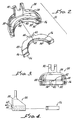
- a single takeout jaw 24 is shown along with a mating insert 26.
- Takeout jaw 24 has a semicircular body 28 and a yoke 30 for attachment to a lifting arm.
- Body 28 has a base 32 and a shelf 34 which form between them a semicircular pocket 36.
- Pocket 36 is open at the front and closed at the rear by semicircular back wall 38 of body 28 except for an opening 40 in the center of back wall 38.
- a center portion 42 is the lower surface of shelf 34 is cut out to provide clearance for a spring clip, not shown.
- Insert 26 is generally semicircular in form except for a lug 44 formed by cutting notches in the back wall 46 of insert 26.
- the upper surface 48 of insert 26 has a depression 50 with a hole 52 in the bottom thereof. Hole 52 is used for locating or fixturing purposes in machining insert 26 to the desired dimensions.
- the front surface 54 is generally semicircular except for two flat portions 56 at either end of the semicircle. If desired, front surface 54 can be threaded to provide a convenient means for contacting bottles having threaded finishes.
- Fig. 3 in addition to the features described with respect to Fig. 2, has a spring clip 58 shown in opening 40 at center portion 42.
- Fig. 4 shows the several horizontal surfaces in phantom and also shows that the insert is adapted to be positioned within the pocket in the takeout jaw and that the spring clip and depression in the insert are lined up to be engaged.
- Spring clip 58 is attached to back wall 38 of takeout jaw 24 by means of a screw 60 and a washer 62.
- Figs. 5, 6, 7 and 8 illustrate how the insert fits within the takeout jaw.
- the spring clip is normally untensioned as shown particularly in Fig. 6.
- the lug 44 engages spring clip 58 and causes it to become tensioned.
- spring clip 58 is snapped into depression 50 and becomes untensioned as in Fig. 6. Removal of insert 26 from takeout jaw 24 will then require exertion of a large force to tension spring clip 58 allowing removal of insert 26 from takeout jaw 24.
- graphite is the material of choice for fabricating the takeout jaw inserts of the present invention.
- Various grades of graphite are commercially available.
- a particularly desirable material is a fine particle, high strength, isotropic graphite available from POCO Graphite, Inc., a subsidiary of UNOCAL Corporation, Decatur, Texas, which is sold as GLASSMATE R graphite contact material.
Landscapes
- Engineering & Computer Science (AREA)
- Chemical & Material Sciences (AREA)
- Manufacturing & Machinery (AREA)
- Materials Engineering (AREA)
- Organic Chemistry (AREA)
- Re-Forming, After-Treatment, Cutting And Transporting Of Glass Products (AREA)
- Eye Examination Apparatus (AREA)
- Reverberation, Karaoke And Other Acoustics (AREA)
- Control And Other Processes For Unpacking Of Materials (AREA)
- Filling Of Jars Or Cans And Processes For Cleaning And Sealing Jars (AREA)
- Details Of Rigid Or Semi-Rigid Containers (AREA)
- Medicines Containing Plant Substances (AREA)
- Packaging Of Special Articles (AREA)
- Diaphragms For Electromechanical Transducers (AREA)
- Table Equipment (AREA)
- Electrical Discharge Machining, Electrochemical Machining, And Combined Machining (AREA)
- Straightening Metal Sheet-Like Bodies (AREA)
- Clamps And Clips (AREA)
- Containers Having Bodies Formed In One Piece (AREA)
Claims (31)
- Ensemble d'enlèvement à mâchoires pour manipuler des articles en verre chaud, ledit ensemble comprenant :(i) un support comprenant une paroi (38), et un élément supérieur et un élément inférieur formant tablette (32, 34), ladite paroi et lesdits éléments formant tablette formant une poche sensiblement arquée (36) ; et(ii) un insert (26) monté de façon appariée dans la poche (36) dudit support, ledit insert présentant des moyens de contact (54) contre le verte, en projection vers l'intérieur et sensiblement arqués, qui s'étendent au-delà desdits éléments en forme de tablette pour venir en contact contre des articles de verre chaud ;
l'ensemble étant caractérisé par :(iii) des moyens formant ressort (58), supportés depuis la paroi (38) dudit support et engageant ledit insert (26) dans une partie centrale arrière de celui-ci, afin de retenir de manière immobile mais détachable ledit insert dans ladite poche. - Ensemble d'enlèvement à mâchoires selon la revendication 1, caractérisé en ce que lesdits moyens formant ressort (58) comprennent un ressort qui est fixé au support et qui s'engage dans une dépression (50) dans une surface de l'insert.
- Ensemble d'enlèvement à mâchoires selon l'une quelconque des revendications précédentes, caractérisé en ce que le support comprend un étrier (30) qui s'étend vers le haut depuis ladite paroi (38) afin d'engager des organes de soulèvement.
- Ensemble d'enlèvement à mâchoires selon l'une quelconque des revendications précédentes, caractérisé en ce que l'insert (26) est un élément arqué sensiblement monolithique.
- Ensemble d'enlèvement à mâchoires selon l'une quelconque des revendications 1 à 3, caractérisé en ce que la poche (36) est sensiblement semi-circulaire, et en ce que l'insert (26) est un élément monolithique sensiblement semi-circulaire, l'insert ayant des surfaces frontale et arrière sensiblement semi-circulaires en relation annulaire.
- Ensemble d'enlèvement à mâchoires selon l'une quelconque des revendications précédentes, caractérisé en ce que ledit insert comporte une dépression (50) formée dans une surface adjacente à son bord arrière afin de recevoir ledit ressort (58).
- Ensemble d'enlèvement à mâchoires selon les revendications 1, 3, 4 ou 5, caractérisé en outre en ce que :(i) ledit élément supérieur et ledit élément inférieur dudit support formant tablettes (32, 34) sont sensiblement parallèles ;(ii) ledit insert (26), placé dans ladite poche (36), comporte une dépression (50) en position adjacente à un bord arrière de celui-ci ; et(iii) lesdits moyens formant ressort comprenant un ressort plat (58) attaché à une surface extérieure de la paroi (38), le ressort s'étendant à travers une ouverture (40) dans la paroi et engageant la dépression dans ledit insert.
- Ensemble d'enlèvement à mâchoires selon la revendication 1, caractérisé en ce que :(i) le support comprend :- une paroi semi-circulaire (38) ayant des surfaces frontale et arrière ;- des tablettes supérieure et inférieure semi-circulaires (32, 34) perpendiculaires à ladite paroi et se projetant parallèlement depuis ladite surface frontale, les tablettes formant une poche semi-circulaire (36) avec ladite paroi au fond dudit support ; et- un étrier (30) qui s'étend vers le haut depuis ladite paroi ;(ii) ledit insert (26) est un élément annulaire sensiblement semi-circulaire, qui comprend en outre une languette (44) formée sur un bord arrière (46) dudit insert et s'étendant de façon appariée dans une ouverture (40) dans ladite paroi (38), ladite languette comportant une dépression (50) qui s'étend sensiblement parallèlement au diamètre dudit insert semi-circulaire ; et(iii) lesdits moyens formant ressort comprenant une agrafe élastique (58) attachée sur l'extérieur de la paroi dudit support et s'étendant à travers une ouverture (40) dans ladite paroi, formée par des découpes (42) dans ladite paroi et dans ladite tablette supérieure, ladite agrafe élastique et ladite dépression étant en relation d'accouplement afin de retenir de façon immobile ledit insert à l'intérieur de ladite poche.
- Ensemble d'enlèvement à mâchoires selon l'une quelconque des revendications 2 à 5, 7 et 8, caractérisé en ce que ledit insert (26) présente une dépression (50) dans une languette (44) située sensiblement au centre dans la partie arrière dudit insert (26).
- Ensemble d'enlèvement à mâchoires selon l'une quelconque des revendications précédentes, caractérisé en ce que le support est métallique.
- Ensemble d'enlèvement à mâchoires selon l'une quelconque des revendications 1 à 9, caractérisé en ce que ledit support est fabriqué en acier usiné.
- Ensemble d'enlèvement à mâchoires selon l'une quelconque des revendications précédentes, caractérisé en ce qu'il contient un seul ressort (58).
- Ensemble d'enlèvement à mâchoires selon la revendication 12, caractérisé en ce que l'insert (26) est maintenu immobile en place par un organe formant ressort qui comprend une seule agrafe élastique plane (58) fixée à une extrémité sur la surface arrière de ladite paroi (38), ladite agrafe élastique s'étendant dans une direction sensiblement horizontale le long d'une partie de la surface supérieure (48) dudit insert, ladite agrafe élastique engageant une dépression (50) dans la partie arrière dudit insert.
- Ensemble d'enlèvement à mâchoires selon l'une ou l'autre des revendications 12 et 13, caractérisé en ce que ledit ressort (58) est situé au centre dans ladite poche (36), en recoupant le support et l'insert sensiblement symétriquement par rapport à un plan vertical.
- Ensemble d'enlèvement à mâchoires selon la revendication 14, caractérisé en ce que la dépression (50) comprend une fente longitudinale dans la surface supérieure d'une languette (44) dans la partie arrière dudit insert, ladite fente s'étendant perpendiculairement audit plan vertical.
- Ensemble d'enlèvement à mâchoires selon l'une quelconque des revendications précédentes, caractérisé en ce que lesdits moyens de contact comprennent au moins un bord sensiblement arqué, en projection radiale vers l'intérieur, qui s'étend au-delà des éléments formant tablette (32, 34) pour venir en contact contre les articles de verre chaud.
- Ensemble d'enlèvement à mâchoires selon la revendication 16, caractérisé en ce que ledit bord se projetant radialement vers l'intérieur est sensiblement semi-circulaire.
- Ensemble d'enlèvement à mâchoires selon l'une quelconque des revendications précédentes, caractérisé en ce que l'insert (26) est non métallique.
- Ensemble d'enlèvement à mâchoires selon l'une quelconque des revendications 1 à 17, caractérisé en ce que l'insert (26) est composé de graphite.
- Support d'enlèvement à mâchoires comprenant :- une paroi arquée (38) de laquelle se projettent une tablette supérieure et une tablette inférieure (32, 34) formant une poche sensiblement arquée (36) pour recevoir de façon appariée et pour retenir un insert arqué (26) pour venir en contact contre les articles de verre chaud,- ledit support étant caractérisé par des moyens formant ressort (58) pour maintenir ledit insert dans une partie centrale arrière de celui-ci, de façon immobile mais détachable dans ladite poche.
- Support d'enlèvement à mâchoires selon la revendication 20, pour réaliser l'ensemble d'enlèvement à mâchoires selon l'une quelconque des revendications 1 à 19.
- Insert d'enlèvement à mâchoires destiné à venir en contact contre des articles de verre chaud, ledit insert comprenant un corps sensiblement arqué qui présente au moins un bord venant en contact avec le verre, et capable d'être placé de façon appariée dans une poche (36) d'un support d'enlèvement à mâchoires, ledit insert étant caractérisé par une dépression (50) dans l'une de ses surfaces à un emplacement sensiblement central et postérieur afin de s'apparier avec des moyens formant ressort (58) supportés depuis le support afin de maintenir de façon immobile mais détachable ledit insert à l'intérieur de ladite poche.
- Insert d'enlèvement à mâchoires selon la revendication 22, maintenu à l'intérieur de la poche dudit support pour former l'ensemble d'enlèvement à mâchoires selon l'une quelconque des revendications 1 à 19.
- Insert d'enlèvement à mâchoires selon l'une ou l'autre des revendications 22 et 23, caractérisé en ce qu'il comprend :- un corps arqué sensiblement monolithique présentant une surface arquée frontale et une surface arquée postérieure (46, 54) en relation sensiblement annulaire, ladite surface frontale présentant un bord sensiblement arqué, en projection radiale vers l'intérieur, afin de venir en contact avec des articles en verre chaud ;- une languette (44) qui comporte une dépression (50), ladite languette s'étendant vers l'extérieur depuis la position centrale de ladite surface postérieure (46) ; et- ledit insert pouvant être reçu à l'intérieur de la poche du support et étant maintenu de façon immobile dans celui-ci par une relation appariée entre les moyens formant ressort et la dépression.
- Insert d'enlèvement à mâchoires selon la revendication 24, caractérisé en ce que :(1) l'insert a la forme d'un corps monolithique annulaire sensiblement semi-circulaire qui se termine par deux bords sensiblement plans (56) qui sont situés à des extrémités opposées du diamètre dudit corps monolithique annulaire semi-circulaire ; et(2) la dépression (50) s'étend sous la forme d'une fente longitudinale dans la languette dans une direction parallèle audit diamètre.
- Insert d'enlèvement à mâchoires selon l'une quelconque des revendications 22 à 25, caractérisé en ce qu'il présente une surface plane supérieure (48) et une surface plane inférieure, lesdites surfaces étant situées dans des plans sensiblement parallèles, ladite surface plane supérieure (48) comportant la dépression (50).
- Insert d'enlèvement à mâchoires selon l'une quelconque des revendications 22, 23 ou 24, caractérisé en ce que le corps est un corps monolithique sensiblement semi-circulaire défini par une surface supérieure sensiblement plane (48), une surface inférieure sensiblement plane et parallèle à la surface supérieure, deux surfaces terminales planes (56) qui définissent chaque extrémité du corps semi-circulaire, une surface frontale incurvée (54), et une surface postérieure incurvée (46) et en relation sensiblement annulaire avec la surface frontale, ladite surface frontale et ladite surface arrière s'étendant entre les deux surfaces terminales planes, la surface frontale comportant un bord en projection vers l'intérieur destiné à venir en contact avec le verre, qui peut être accouplé de façon précise avec un article en verre chaud.
- Insert d'enlèvement à mâchoires selon l'une quelconque des revendications 22, 23 ou 24, caractérisé par un corps sensiblement semi-circulaire sous la forme d'un fragment annulaire, comportant une surface frontale (54) et une surface postérieure (46) incurvées de façon sensiblement semi-circulaire, la surface frontale comportant un bord en projection vers l'intérieur afin de venir en contact contre des articles en verre chaud.
- Insert d'enlèvement à mâchoires selon l'une quelconque des revendications 22 à 28, caractérisé par un bord en projection vers l'intérieur sur la surface frontale (54), qui comprend des reliefs en hélice afin de venir en contact contre des bouteilles chaudes filetées.
- Insert d'enlèvement à mâchoires selon l'une quelconque des revendications 24 à 29, caractérisé en ce qu'il est susceptible d'être recoupé symétriquement par un plan vertical.
- Insert d'enlèvement à mâchoires selon l'une quelconque des revendications 22 à 30, composé en graphite.
Applications Claiming Priority (4)
| Application Number | Priority Date | Filing Date | Title |
|---|---|---|---|
| US401038 | 1989-08-31 | ||
| US07/401,038 US4995896A (en) | 1989-08-31 | 1989-08-31 | Takeout jaws |
| PCT/US1990/004852 WO1991003431A1 (fr) | 1989-08-31 | 1990-08-27 | Machoires d'enlevement |
| SG2495A SG2495G (en) | 1989-08-31 | 1995-01-09 | Takeout jaws |
Publications (2)
| Publication Number | Publication Date |
|---|---|
| EP0489823A1 EP0489823A1 (fr) | 1992-06-17 |
| EP0489823B1 true EP0489823B1 (fr) | 1994-11-30 |
Family
ID=26663756
Family Applications (1)
| Application Number | Title | Priority Date | Filing Date |
|---|---|---|---|
| EP90913368A Revoked EP0489823B1 (fr) | 1989-08-31 | 1990-08-27 | Machoires d'enlevement |
Country Status (13)
| Country | Link |
|---|---|
| US (1) | US4995896A (fr) |
| EP (1) | EP0489823B1 (fr) |
| JP (1) | JPH05502010A (fr) |
| KR (1) | KR100189581B1 (fr) |
| AT (1) | ATE114615T1 (fr) |
| AU (1) | AU647047B2 (fr) |
| DE (1) | DE69014639T2 (fr) |
| DK (1) | DK0489823T3 (fr) |
| ES (1) | ES2065547T3 (fr) |
| HK (1) | HK27295A (fr) |
| PH (1) | PH27193A (fr) |
| SG (1) | SG2495G (fr) |
| WO (1) | WO1991003431A1 (fr) |
Families Citing this family (10)
| Publication number | Priority date | Publication date | Assignee | Title |
|---|---|---|---|---|
| US5324340A (en) * | 1992-06-30 | 1994-06-28 | Union Oil Company Of California | Contact fixture for hot glass |
| US5769920A (en) * | 1992-08-27 | 1998-06-23 | Union Oil Company Of California | Graphite guide rings |
| JPH07187687A (ja) * | 1993-12-27 | 1995-07-25 | Nippon Electric Glass Co Ltd | 中空ガラス物品の製造方法及び装置 |
| USD429494S (en) * | 1999-12-02 | 2000-08-15 | Graphite Sales, Inc. | Replacement insert for a takeout jaw |
| ITTO20080915A1 (it) * | 2008-12-09 | 2010-06-10 | Tetra Laval Holdings & Finance | Unita' per l'applicazione di dispositivi di apertura su confezioni di prodotti alimentari versabili in un tubo di materiale di confezionamento |
| WO2012037569A2 (fr) * | 2010-09-17 | 2012-03-22 | Poco Graphite, Inc. | Mâchoires d'extraction comprenant des composants fixés |
| CZ303523B6 (cs) * | 2011-09-21 | 2012-11-07 | Componenta Moravia S. R. O. | Držák celisti odnímace sklenených výrobku, zejména obalového skla |
| CN102730407A (zh) * | 2012-07-10 | 2012-10-17 | 德清才府玻璃股份有限公司 | 一种瓶钳 |
| US10406694B2 (en) | 2016-04-20 | 2019-09-10 | Agr International, Inc. | Container gripper assembly |
| TWI869763B (zh) * | 2022-01-24 | 2025-01-11 | 美商恩特葛瑞斯股份有限公司 | 玻璃處理裝置及相關方法 |
Family Cites Families (12)
| Publication number | Priority date | Publication date | Assignee | Title |
|---|---|---|---|---|
| US1436825A (en) * | 1921-06-17 | 1922-11-28 | A H Heisey & Company | Glass-finishing tool |
| US2100497A (en) * | 1935-10-05 | 1937-11-30 | Libbey Owens Ford Glass Co | Tong |
| DE1481757A1 (de) * | 1967-03-03 | 1969-03-20 | Heye Hermann Fa | Greif- und Transportvorrichtung fuer Behaelter |
| GB1256181A (en) * | 1969-02-14 | 1971-12-08 | Triplex Safety Glass Co | Improvements in or relating to tongs for suspending glass sheets |
| US3790205A (en) * | 1972-09-25 | 1974-02-05 | W Wenz | Takeout tong assembly |
| US3938847A (en) * | 1972-11-13 | 1976-02-17 | Industrial Automation Corporation | Gripper means |
| DE2257453C2 (de) * | 1972-11-23 | 1974-05-16 | Philips Patentverwaltung Gmbh, 2000 Hamburg | Werkzeug für die Warmbearbeitung von Glas |
| DE2722689C2 (de) * | 1977-05-18 | 1983-02-03 | Alfred Ing.(grad.) 8160 Miesbach Kinshofer | Auf eine Greifzange unrüstbarer Zweischalengreifer |
| SU854709A2 (ru) * | 1979-11-11 | 1981-08-15 | За витель | Исполнительный орган манипул тора |
| US4298373A (en) * | 1980-01-14 | 1981-11-03 | Owens-Illinois, Inc. | Apparatus for cushioning the motion of reciprocating members |
| SU1006209A1 (ru) * | 1981-02-27 | 1983-03-23 | Марийский Политехнический Институт Им.М.Горького | Схват дл цилиндрических деталей |
| GB2126211A (en) * | 1982-07-26 | 1984-03-21 | United Glass Plc | Take-out tongs for use in the manufacture of glassware |
-
1989
- 1989-08-31 US US07/401,038 patent/US4995896A/en not_active Ceased
-
1990
- 1990-08-10 PH PH41010A patent/PH27193A/en unknown
- 1990-08-27 JP JP2512541A patent/JPH05502010A/ja active Pending
- 1990-08-27 EP EP90913368A patent/EP0489823B1/fr not_active Revoked
- 1990-08-27 AU AU63346/90A patent/AU647047B2/en not_active Expired
- 1990-08-27 DE DE69014639T patent/DE69014639T2/de not_active Revoked
- 1990-08-27 ES ES90913368T patent/ES2065547T3/es not_active Expired - Lifetime
- 1990-08-27 WO PCT/US1990/004852 patent/WO1991003431A1/fr not_active Ceased
- 1990-08-27 DK DK90913368.8T patent/DK0489823T3/da active
- 1990-08-27 AT AT90913368T patent/ATE114615T1/de not_active IP Right Cessation
- 1990-08-31 KR KR1019900013745A patent/KR100189581B1/ko not_active Expired - Fee Related
-
1995
- 1995-01-09 SG SG2495A patent/SG2495G/en unknown
- 1995-03-02 HK HK27295A patent/HK27295A/xx unknown
Also Published As
| Publication number | Publication date |
|---|---|
| SG2495G (en) | 1995-06-16 |
| AU6334690A (en) | 1991-04-08 |
| AU647047B2 (en) | 1994-03-17 |
| EP0489823A1 (fr) | 1992-06-17 |
| KR100189581B1 (ko) | 1999-06-01 |
| DE69014639T2 (de) | 1995-05-24 |
| PH27193A (en) | 1993-04-16 |
| ATE114615T1 (de) | 1994-12-15 |
| US4995896A (en) | 1991-02-26 |
| DK0489823T3 (da) | 1995-05-08 |
| HK27295A (en) | 1995-03-10 |
| DE69014639D1 (de) | 1995-01-12 |
| WO1991003431A1 (fr) | 1991-03-21 |
| KR910004485A (ko) | 1991-03-28 |
| JPH05502010A (ja) | 1993-04-15 |
| ES2065547T3 (es) | 1995-02-16 |
Similar Documents
| Publication | Publication Date | Title |
|---|---|---|
| EP0489823B1 (fr) | Machoires d'enlevement | |
| USRE34953E (en) | Takeout jaw insert and assembly | |
| EP1877347B1 (fr) | Systeme, procede et appareil pour l'implantation interchangeable d'elements fixes et flottants de prelevement | |
| EP0497267A1 (fr) | Machine de traitement de semiconducteurs et système de suspension associé | |
| US5741343A (en) | Adjustable hot glass transfer device | |
| US5324340A (en) | Contact fixture for hot glass | |
| US7472565B1 (en) | Plastic takeout holder and ceramic insert for use in bottle manufacturing | |
| CN112195510A (zh) | 一种碳纤维碗形预制体及碳碳碗体及坩埚 | |
| US5814120A (en) | Sweepout assembly with nonmetallic pads | |
| US7814766B2 (en) | System and apparatus for adjustable stacker bar assembly having vertical accommodation features | |
| EP0800487A1 (fr) | Douilles de guidage en graphite | |
| CN115648194A (zh) | 浮动抓取装置 | |
| AU2011301790B2 (en) | Take out jaws with seated componentry | |
| US4966619A (en) | Dead plate assembly | |
| CN220681145U (zh) | 一种用于模具内部的隔板结构 | |
| CN223807582U (zh) | 一种旋转加热炉内的定位装置 | |
| CN213997672U (zh) | 一种机器人抓手 | |
| CN215614613U (zh) | 一种新型柔性端拾器结构 | |
| JP4848194B2 (ja) | モールドプレス成形型、及び光学素子の製造方法 |
Legal Events
| Date | Code | Title | Description |
|---|---|---|---|
| PUAI | Public reference made under article 153(3) epc to a published international application that has entered the european phase |
Free format text: ORIGINAL CODE: 0009012 |
|
| 17P | Request for examination filed |
Effective date: 19920325 |
|
| AK | Designated contracting states |
Kind code of ref document: A1 Designated state(s): AT BE CH DE DK ES FR GB IT LI LU NL SE |
|
| 17Q | First examination report despatched |
Effective date: 19930716 |
|
| GRAA | (expected) grant |
Free format text: ORIGINAL CODE: 0009210 |
|
| AK | Designated contracting states |
Kind code of ref document: B1 Designated state(s): AT BE CH DE DK ES FR GB IT LI LU NL SE |
|
| REF | Corresponds to: |
Ref document number: 114615 Country of ref document: AT Date of ref document: 19941215 Kind code of ref document: T |
|
| REF | Corresponds to: |
Ref document number: 69014639 Country of ref document: DE Date of ref document: 19950112 |
|
| REG | Reference to a national code |
Ref country code: ES Ref legal event code: FG2A Ref document number: 2065547 Country of ref document: ES Kind code of ref document: T3 |
|
| ITF | It: translation for a ep patent filed | ||
| ET | Fr: translation filed | ||
| REG | Reference to a national code |
Ref country code: DK Ref legal event code: T3 |
|
| PGFP | Annual fee paid to national office [announced via postgrant information from national office to epo] |
Ref country code: LU Payment date: 19950701 Year of fee payment: 6 |
|
| PGFP | Annual fee paid to national office [announced via postgrant information from national office to epo] |
Ref country code: SE Payment date: 19950713 Year of fee payment: 6 Ref country code: CH Payment date: 19950713 Year of fee payment: 6 |
|
| PGFP | Annual fee paid to national office [announced via postgrant information from national office to epo] |
Ref country code: FR Payment date: 19950717 Year of fee payment: 6 |
|
| PGFP | Annual fee paid to national office [announced via postgrant information from national office to epo] |
Ref country code: NL Payment date: 19950719 Year of fee payment: 6 Ref country code: DK Payment date: 19950719 Year of fee payment: 6 |
|
| PGFP | Annual fee paid to national office [announced via postgrant information from national office to epo] |
Ref country code: AT Payment date: 19950720 Year of fee payment: 6 |
|
| PGFP | Annual fee paid to national office [announced via postgrant information from national office to epo] |
Ref country code: DE Payment date: 19950725 Year of fee payment: 6 |
|
| PGFP | Annual fee paid to national office [announced via postgrant information from national office to epo] |
Ref country code: GB Payment date: 19950727 Year of fee payment: 6 |
|
| PGFP | Annual fee paid to national office [announced via postgrant information from national office to epo] |
Ref country code: BE Payment date: 19950731 Year of fee payment: 6 |
|
| PGFP | Annual fee paid to national office [announced via postgrant information from national office to epo] |
Ref country code: ES Payment date: 19950809 Year of fee payment: 6 |
|
| PLBI | Opposition filed |
Free format text: ORIGINAL CODE: 0009260 |
|
| PLAB | Opposition data, opponent's data or that of the opponent's representative modified |
Free format text: ORIGINAL CODE: 0009299OPPO |
|
| 26 | Opposition filed |
Opponent name: UNION OIL COMPANY OF CALIFORNIA Effective date: 19950830 Opponent name: SCHUNK KOHLENSTOFFTECHNIK GMBH Effective date: 19950830 |
|
| R26 | Opposition filed (corrected) |
Opponent name: SCHUNK KOHLENSTOFFTECHNIK GMBH * 950830 JOHNSON RA Effective date: 19950830 |
|
| NLR1 | Nl: opposition has been filed with the epo |
Opponent name: UNION OIL COMPANY OF CALIFORNIA Opponent name: SCHUNK KOHLENSTOFFTECHNIK GMBH |
|
| NLR1 | Nl: opposition has been filed with the epo |
Opponent name: JOHNSON RADLEY LIMITED Opponent name: SCHUNK KOHLENSTOFFTECHNIK GMBH |
|
| PLBQ | Unpublished change to opponent data |
Free format text: ORIGINAL CODE: EPIDOS OPPO |
|
| PLAB | Opposition data, opponent's data or that of the opponent's representative modified |
Free format text: ORIGINAL CODE: 0009299OPPO |
|
| PLBF | Reply of patent proprietor to notice(s) of opposition |
Free format text: ORIGINAL CODE: EPIDOS OBSO |
|
| REG | Reference to a national code |
Ref country code: DK Ref legal event code: EBP |
|
| R26 | Opposition filed (corrected) |
Opponent name: SCHUNK KOHLENSTOFFTECHNIK GMBH * 950830 JOHNSON RA Effective date: 19950830 |
|
| NLR1 | Nl: opposition has been filed with the epo |
Opponent name: JOHNSON RADLEY LIMITED Opponent name: SCHUNK KOHLENSTOFFTECHNIK GMBH |
|
| RDAG | Patent revoked |
Free format text: ORIGINAL CODE: 0009271 |
|
| STAA | Information on the status of an ep patent application or granted ep patent |
Free format text: STATUS: PATENT REVOKED |
|
| REG | Reference to a national code |
Ref country code: CH Ref legal event code: PL |
|
| 27W | Patent revoked |
Effective date: 19960311 |
|
| GBPR | Gb: patent revoked under art. 102 of the ep convention designating the uk as contracting state |
Free format text: 960311 |
|
| NLR2 | Nl: decision of opposition |