EP0490548A2 - Kraftübertragung für ein Fahrzeug - Google Patents
Kraftübertragung für ein Fahrzeug Download PDFInfo
- Publication number
- EP0490548A2 EP0490548A2 EP91311161A EP91311161A EP0490548A2 EP 0490548 A2 EP0490548 A2 EP 0490548A2 EP 91311161 A EP91311161 A EP 91311161A EP 91311161 A EP91311161 A EP 91311161A EP 0490548 A2 EP0490548 A2 EP 0490548A2
- Authority
- EP
- European Patent Office
- Prior art keywords
- transmission
- shaft
- clutch
- shift
- main shaft
- Prior art date
- Legal status (The legal status is an assumption and is not a legal conclusion. Google has not performed a legal analysis and makes no representation as to the accuracy of the status listed.)
- Granted
Links
- 230000005540 biological transmission Effects 0.000 title claims abstract description 74
- 230000007246 mechanism Effects 0.000 claims abstract description 63
- 239000003921 oil Substances 0.000 claims description 57
- 230000002441 reversible effect Effects 0.000 claims description 33
- 239000010687 lubricating oil Substances 0.000 claims description 24
- 229920001971 elastomer Polymers 0.000 claims description 12
- 239000005060 rubber Substances 0.000 claims description 12
- 238000013016 damping Methods 0.000 claims description 5
- 230000002093 peripheral effect Effects 0.000 claims description 5
- 230000035939 shock Effects 0.000 claims description 5
- 238000010276 construction Methods 0.000 description 13
- 230000009467 reduction Effects 0.000 description 9
- 238000012423 maintenance Methods 0.000 description 5
- 238000005192 partition Methods 0.000 description 5
- 238000004891 communication Methods 0.000 description 4
- 230000004044 response Effects 0.000 description 4
- 230000008878 coupling Effects 0.000 description 3
- 238000010168 coupling process Methods 0.000 description 3
- 238000005859 coupling reaction Methods 0.000 description 3
- 230000000717 retained effect Effects 0.000 description 3
- 230000003247 decreasing effect Effects 0.000 description 2
- 230000006872 improvement Effects 0.000 description 2
- 230000001360 synchronised effect Effects 0.000 description 2
- 230000009471 action Effects 0.000 description 1
- 230000001154 acute effect Effects 0.000 description 1
- 230000015572 biosynthetic process Effects 0.000 description 1
- 230000000994 depressogenic effect Effects 0.000 description 1
- 238000013461 design Methods 0.000 description 1
- 238000007654 immersion Methods 0.000 description 1
- 238000003780 insertion Methods 0.000 description 1
- 230000037431 insertion Effects 0.000 description 1
- 230000001050 lubricating effect Effects 0.000 description 1
- 239000000463 material Substances 0.000 description 1
- 238000012986 modification Methods 0.000 description 1
- 230000004048 modification Effects 0.000 description 1
- 230000007935 neutral effect Effects 0.000 description 1
- 230000004043 responsiveness Effects 0.000 description 1
- 239000007858 starting material Substances 0.000 description 1
- -1 therefore Substances 0.000 description 1
Images





Classifications
-
- F—MECHANICAL ENGINEERING; LIGHTING; HEATING; WEAPONS; BLASTING
- F16—ENGINEERING ELEMENTS AND UNITS; GENERAL MEASURES FOR PRODUCING AND MAINTAINING EFFECTIVE FUNCTIONING OF MACHINES OR INSTALLATIONS; THERMAL INSULATION IN GENERAL
- F16H—GEARING
- F16H3/00—Toothed gearings for conveying rotary motion with variable gear ratio or for reversing rotary motion
- F16H3/02—Toothed gearings for conveying rotary motion with variable gear ratio or for reversing rotary motion without gears having orbital motion
- F16H3/08—Toothed gearings for conveying rotary motion with variable gear ratio or for reversing rotary motion without gears having orbital motion exclusively or essentially with continuously meshing gears, that can be disengaged from their shafts
- F16H3/087—Toothed gearings for conveying rotary motion with variable gear ratio or for reversing rotary motion without gears having orbital motion exclusively or essentially with continuously meshing gears, that can be disengaged from their shafts characterised by the disposition of the gears
- F16H3/089—Toothed gearings for conveying rotary motion with variable gear ratio or for reversing rotary motion without gears having orbital motion exclusively or essentially with continuously meshing gears, that can be disengaged from their shafts characterised by the disposition of the gears all of the meshing gears being supported by a pair of parallel shafts, one being the input shaft and the other the output shaft, there being no countershaft involved
-
- B—PERFORMING OPERATIONS; TRANSPORTING
- B60—VEHICLES IN GENERAL
- B60K—ARRANGEMENT OR MOUNTING OF PROPULSION UNITS OR OF TRANSMISSIONS IN VEHICLES; ARRANGEMENT OR MOUNTING OF PLURAL DIVERSE PRIME-MOVERS IN VEHICLES; AUXILIARY DRIVES FOR VEHICLES; INSTRUMENTATION OR DASHBOARDS FOR VEHICLES; ARRANGEMENTS IN CONNECTION WITH COOLING, AIR INTAKE, GAS EXHAUST OR FUEL SUPPLY OF PROPULSION UNITS IN VEHICLES
- B60K17/00—Arrangement or mounting of transmissions in vehicles
- B60K17/04—Arrangement or mounting of transmissions in vehicles characterised by arrangement, location or kind of gearing
- B60K17/06—Arrangement or mounting of transmissions in vehicles characterised by arrangement, location or kind of gearing of change-speed gearing
- B60K17/08—Arrangement or mounting of transmissions in vehicles characterised by arrangement, location or kind of gearing of change-speed gearing of mechanical type
-
- F—MECHANICAL ENGINEERING; LIGHTING; HEATING; WEAPONS; BLASTING
- F16—ENGINEERING ELEMENTS AND UNITS; GENERAL MEASURES FOR PRODUCING AND MAINTAINING EFFECTIVE FUNCTIONING OF MACHINES OR INSTALLATIONS; THERMAL INSULATION IN GENERAL
- F16D—COUPLINGS FOR TRANSMITTING ROTATION; CLUTCHES; BRAKES
- F16D41/00—Freewheels or freewheel clutches
- F16D41/06—Freewheels or freewheel clutches with intermediate wedging coupling members between an inner and an outer surface
- F16D41/08—Freewheels or freewheel clutches with intermediate wedging coupling members between an inner and an outer surface with provision for altering the freewheeling action
- F16D41/086—Freewheels or freewheel clutches with intermediate wedging coupling members between an inner and an outer surface with provision for altering the freewheeling action the intermediate members being of circular cross-section and wedging by rolling
- F16D41/088—Freewheels or freewheel clutches with intermediate wedging coupling members between an inner and an outer surface with provision for altering the freewheeling action the intermediate members being of circular cross-section and wedging by rolling the intermediate members being of only one size and wedging by a movement not having an axial component, between inner and outer races, one of which is cylindrical
-
- F—MECHANICAL ENGINEERING; LIGHTING; HEATING; WEAPONS; BLASTING
- F16—ENGINEERING ELEMENTS AND UNITS; GENERAL MEASURES FOR PRODUCING AND MAINTAINING EFFECTIVE FUNCTIONING OF MACHINES OR INSTALLATIONS; THERMAL INSULATION IN GENERAL
- F16D—COUPLINGS FOR TRANSMITTING ROTATION; CLUTCHES; BRAKES
- F16D41/00—Freewheels or freewheel clutches
- F16D41/06—Freewheels or freewheel clutches with intermediate wedging coupling members between an inner and an outer surface
- F16D41/08—Freewheels or freewheel clutches with intermediate wedging coupling members between an inner and an outer surface with provision for altering the freewheeling action
- F16D41/10—Freewheels or freewheel clutches with intermediate wedging coupling members between an inner and an outer surface with provision for altering the freewheeling action with self-actuated reversing
- F16D41/105—Freewheels or freewheel clutches with intermediate wedging coupling members between an inner and an outer surface with provision for altering the freewheeling action with self-actuated reversing the intermediate members being of circular cross-section, of only one size and wedging by rolling movement not having an axial component between inner and outer races, one of which is cylindrical
-
- F—MECHANICAL ENGINEERING; LIGHTING; HEATING; WEAPONS; BLASTING
- F16—ENGINEERING ELEMENTS AND UNITS; GENERAL MEASURES FOR PRODUCING AND MAINTAINING EFFECTIVE FUNCTIONING OF MACHINES OR INSTALLATIONS; THERMAL INSULATION IN GENERAL
- F16H—GEARING
- F16H3/00—Toothed gearings for conveying rotary motion with variable gear ratio or for reversing rotary motion
- F16H3/02—Toothed gearings for conveying rotary motion with variable gear ratio or for reversing rotary motion without gears having orbital motion
- F16H3/08—Toothed gearings for conveying rotary motion with variable gear ratio or for reversing rotary motion without gears having orbital motion exclusively or essentially with continuously meshing gears, that can be disengaged from their shafts
-
- F—MECHANICAL ENGINEERING; LIGHTING; HEATING; WEAPONS; BLASTING
- F16—ENGINEERING ELEMENTS AND UNITS; GENERAL MEASURES FOR PRODUCING AND MAINTAINING EFFECTIVE FUNCTIONING OF MACHINES OR INSTALLATIONS; THERMAL INSULATION IN GENERAL
- F16H—GEARING
- F16H57/00—General details of gearing
- F16H57/04—Features relating to lubrication or cooling or heating
- F16H57/0434—Features relating to lubrication or cooling or heating relating to lubrication supply, e.g. pumps; Pressure control
-
- F—MECHANICAL ENGINEERING; LIGHTING; HEATING; WEAPONS; BLASTING
- F16—ENGINEERING ELEMENTS AND UNITS; GENERAL MEASURES FOR PRODUCING AND MAINTAINING EFFECTIVE FUNCTIONING OF MACHINES OR INSTALLATIONS; THERMAL INSULATION IN GENERAL
- F16H—GEARING
- F16H63/00—Control outputs from the control unit to change-speed- or reversing-gearings for conveying rotary motion or to other devices than the final output mechanism
- F16H63/02—Final output mechanisms therefor; Actuating means for the final output mechanisms
- F16H63/08—Multiple final output mechanisms being moved by a single common final actuating mechanism
- F16H63/16—Multiple final output mechanisms being moved by a single common final actuating mechanism the final output mechanisms being successively actuated by progressive movement of the final actuating mechanism
- F16H63/18—Multiple final output mechanisms being moved by a single common final actuating mechanism the final output mechanisms being successively actuated by progressive movement of the final actuating mechanism the final actuating mechanism comprising cams
Definitions
- the field of the present invention is vehicle transmissions of the type that have a shift mechanism for establishing a desired shift stage through a plurality of gear trains interposed between a main shaft and a counter shaft, and a synchro mechanism for synchronizing the speed of rotation of the shafts when the shift stage is established
- the arrangement of the main shaft and the counter shaft relative to the crankshaft of the engine is generally such that the main shaft is coaxially connected to one end of the crankshaft through a clutch, and the counter shaft is disposed in parallel to the main shaft (see U.S. Patent No. . 4,817,451, for example).
- a transmission for a vehicle comprising a main shaft to which the rotation of the crankshaft is transmitted, a counter shaft disposed in parallel to the main shaft, a plurality of gear trains interposed between the main shaft and the counter shaft, a shift mechanism for connecting the shafts by any of the gear trains for establishing a desired shift stage, and a synchro mechanism for synchronizing the speed of rotation tions of both shafts when the shift stage is established, the main shaft and the counter shaft being disposed perpendicular to the axis of the crankshaft.
- the main shaft and the counter shaft are disposed perpendicular to the axis of the crankshaft and therefore, as compared with a transmission in which the crankshaft and the main shaft are aligned and interconnected in series, it is possible to reduce the size of the transmission in the axial direction of the crankshaft and increase the freedom of mounting the transmission in the vehicle.
- the axis of the crankshaft intersects the intermediate portions of the main shaft and the counter shaft and preferably also that the low speed gear trains and the high speed gear trains are divided and disposed on opposite sides of such axis.
- the length of the main shaft and the counter shaft may be divided substantially equally on laterally opposite sides of the axis of the crankshaft.
- the synchro mechanism is disposed on the counter shaft, e.g. on a side thereof.
- the synchro mechanism may be disposed on the counter shaft having a gear with a diameter larger than that of the gear on the main shaft and therefore a space for locating the synchro mechanism is easily provided.
- a smooth shifting operation can be conducted.
- a damper for damping the shift shock produced during operation or the synchro mechanism is mounted on the clutch interposed between the crankshaft and the main shaft.
- the shift mechanism includes a rotatable shift drum carrying a shift fork which drives the synchro mechanism, the drum being parallel to the counter shaft.
- the shift drum of the shift mechanism is disposed in parallel to and along the counter shaft and therefore, it is possible to prevent an increase in lateral size of the transmission due to the shift drum.
- the shift drum is connected at its axially intermediate portion to a drive source.
- the axially intermediate portion of the shift drum is connected to and driven by the drive source and therefore the torsion of the shift drum can be reduced to achieve a accurate shifting operation.
- the drive source can be received compactly within the width of a casing of the transmission without projection sideways out of the casing.
- a reverse shift mechanism is mounted independent of the forward shift mechanism between the main shaft and the counter shaft.
- the reverse backward shift mechanism independent of the forward shift mechanism is mounted between the main shaft and the counter shaft and therefore it is possible to prevent an increase in lateral size of the transmission due to the reverse shift mechanism. Moreover, it is possible to improve the reliability of the shifting operation by separating the shift mechanisms.
- the transmission includes a clutch adapted to couple a clutch outer member mounted on the input shaft with a clutch inner member mounted on the output shaft through a clutch disk, the clutch inner member including a damper hub inner member coupled to the output shaft, and a damper hub outer member relatively rotatably carried on the damper hub inner member to transmit torque between the damper hub outer member and the clutch outer member through the clutch disks, wherein the outer peripheral surface of the damper hub inner member is connected with an inner peripheral surface of the damper hub outer member by an annular damper rubber.
- the damper hub outer member and the damper hub inner member constituting the clutch inner member can be relatively rotated to resiliently deform the damper rubber, thereby damping the shock produced due to the variation in torque.
- the damper rubber may comprise a single annular material piece coaxially mounted on the clutch inner member and may be laid out by utilizing the internal space in the clutch outer member and therefore the contour size of the clutch will not be increased.
- the number of parts is substantially decreased as compared with the prior art using a large number of damper rubbers, thereby enabling a reduction in the number of assembling steps and a reduction in cost.
- the transmission includes a clutch disk for transmitting the driving force between the input and output shafts, an annular diaphragm spring disposed around the axes of the input and output shafts for biasing the clutch disk in an engaging direction thereof, a release hub supported for movement along the axes and connected to an inner periphery of the diaphragm spring, a clutch for releasing the engagement of the clutch disk through the diaphragm spring by movement of the release hub, a hollow release piston slidably received in a release cylinder which is disposed around the axes of the input and output shafts, and an annular oil chamber defined between the release cylinder and the release piston and connected to a hydraulic pressure generating source, the release piston being connected to the release hub.
- the transmission includes a pair of coaxially juxtaposed pumps connected to a shaft connected to the crankshaft to supply lubricating oil from an oil reservoir formed at the lower portion of a transmission case to each of those portions in the transmission case which are to be lubricated and a pair of strainers which are connected to the pumps, respectively, and disposed in the oil reservoir at a distance from each other in either the longitudinal or lateral direction of the vehicle.
- the pair of coaxially juxtaposed pumps are connected to the shaft connected to the crankshaft and the pair of strainers connected to the pumps are disposed in the oil reservoir at a distance from each other in either the longitudinal or lateral direction of the vehicle, it is ensured that even if the lubricating oil is moved longitudinally or laterally, depending upon the operational condition of the vehicle, at least one of the strainers will be immersed in the lubricating oil to prevent an interruption in the supply of the lubricating oil.
- the need to provide a wall around each of the strainers can be eliminated, thereby achieving a reduction in size of the transmission case and to easily insure the lowest height of the vehicle above the ground and further to increase the freedom of location of the gear trains.
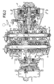
- a transmission for a vehicle comprises a body casing 1 disposed in a longitudinal direction of a vehicle body.
- the body casing 1 has a left side opening covered with a left casing 2, a right side opening covered with a right casing 4 through an intermediate casing 3, and a rear opening covered with a rear casing 5.
- a main shaft 9 is supported in a lateral direction of the vehicle body at a central portion of the body casing 1 through a roller bearing 6 mounted on the left casing 2, a ball bearing 7 mounted on the body casing 1 and a roller bearing 8 mounted on the intermediate casing 3.
- a counter shaft 10 is supported rearwardly of and above the main shaft 9 in parallel to the latter through roller bearings 11, 12 and 13 mounted on the left casing 2, the body casing 1 and the intermediate casing 3, respectively.
- the rear end of the engine crankshaft 14 is disposed in a direction perpendicular to the main shaft 9 and the counter shaft 10, i.e., along a center line of the vehicle body and opposed to the front opening of the body casing 1.
- a transmission input shaft 15 is coaxially supported at its front end on the rear end of the crankshaft 14 with a ball bearing 16 interposed therebetween.
- a driving bevel gear 17 is coupled to a rear end of the transmission input shaft 15 and supported on an annular bracket 18 mounted on the body casing 1 with two ball bearings 19, 20 interposed therebetween. This ensures that the crankshaft 14 and the transmission input shaft 15 are coaxially aligned, relatively rotatable and supported to intersect with the main shaft 9 and counter shaft 10 at right angles.
- the size of the transmission in the axial direction of the crankshaft 14 can be reduced, leading to an increased freedom of mounting of the transmission in the vehicle body.
- a clutch outer 22 is coupled to the rear end of the crankshaft 14 in a manner that the clutch outer is fitted into the front opening of the body casing 1.
- Four clutch disks 23 and a single pressure plate 24 are axially slidably carried in the clutch outer 22.
- a clutch inner is disposed on an inner periphery of the clutch outer 22 and is comprised of a damper hub inner 25 spline-connected to the transmission input shaft 15 and a damper hub outer 26 which is carried on an outer periphery of the damper hub inner 25 for slight rotation relative to each other.
- Three clutch disks 27 are axially slidably carried in the damper hub outer 26 and clamped by the four clutch disks 23 in the clutch outer 22.
- a clearance of an angle ⁇ is provided between each of the projections 25a of the damper hub inner 25 and corresponding one of the recesses 26a of the damper hub outer 26 and adapted to be reduced in spacing during a reduction in the speed of the vehicle, i.e., when the driving force is transmitted from the driving wheels toward the engine.
- An annular damper rubber 28 is mounted between the damper hub inner 25 and the damper hub outer 26 which are loosely fitted with each other to damp the relative rotation of both the damper hub inner 25 and the damper hub outer 26.
- an inner periphery of the damper rubber 28 is fixed to rear portions of the projections 25a of the damper hub inner 25 by baking and a ring member 29 to which an outer periphery of the damper rubber 28 is fixed by baking is spline-connected to an inner periphery of the damper hub outer 26.
- a release cylinder 30 of the clutch 21 is fixed to the annular bracket 18 supported on the body casing 1.
- the release cylinder 30 is supported in such a manner that it covers an outer periphery of the transmission input shaft 15 and is received in a recess 17a provided in the driving bevel gear 17.
- a release piston 31 is received in the release cylinder 30 for axial sliding movement so as likewise to cover the outer periphery of the transmission input shaft 15.
- a release hub 33 is carried on a front end of the release piston 31 with a release bearing 32 interposed therebetween.
- the release hub 33 is pivotally supported at its intermediate portion on the clutch outer 22 by a pin 34 and abuts against an inner periphery of a diaphragm spring 35 having an outer periphery abutting against the pressure plate 24.
- An oil passage 39 is defined between the release cylinder 30 and the release piston 31 for permitting the supply of a pressure oil via a coupling 37 and a pipe 38 to an annular chamber 36, and a pressure sensor 40 is provided in the oil passage 39 for detecting the magnitude of an oil pressure in the oil passage 39. Since the release cylinder 30 and the release piston 31 of the clutch 21 are fitted over the outer periphery of the transmission input shaft 15 and received in the recess 17a in the driving bevel gear 17 in the above manner, the release mechanism is very compact.
- a first gear train G1 to a seventh gear train G7 are provided on the main shaft 9 and the counter shaft 10. These gear trains G1 to G7 are arranged in such a manner that the first and second gear trains G1 and G2 are disposed on the left side of the center line of the transmission, i.e., of the crankshaft 14 and the transmission input shaft 15, while the third gear train G3 is in the center and the fourth to seventh gear trains G4 to G7 are disposed on the right side.
- a follower bevel gear 41 is spline-connected to the main shaft 9 to lie between the first and third gear trains G1 and G3 and is meshed with the driving bevel gear 17 provided on the transmission input shaft 15.
- Two hydraulic pumps 42 and 43 are juxtaposed in a tandem fashion on the right side of the follower bevel gear 41.
- a revolution speed sensor 44 is mounted at the left end of the main shaft 9 for detecting the revolution speed of the main shaft 9.
- a starting gear 45 is mounted at the right end of the main shaft 9 and connected to an external starter motor which is not shown.
- An output gear 46 is formed on the counter shaft 10 to lie between the first and third gear trains G1 and G3 and is meshed with an input gear 48 of a conventional differential 47 enclosed by the rear end of the body casing 1 and a rear cover 5.
- a revolution speed sensor 49 is mounted at the left end of the counter shaft 10 for detecting the revolution speed of the counter shaft 10.
- a roller synchro mechanism S12 is provided between the first and second gear trains G1 and G2 for selectively establishing a first shift stage and a second shift stage.
- a roller synchro mechanism S34 is provided between the third and fourth gear trains G3 and G4 for selectively establishing a third shift stage and a fourth shift stage.
- a roller synchro mechanism S56 is provided between the fifth and sixth gear trains G5 and G6 for selectively establishing a fifth shift stage and a sixth shift stage.
- a roller synchro mechanism S7 is provided in the vicinity of the seventh gear train G7 for establishing a seventh shift stage.
- the concentrative disposition of the roller synchro mechanisms S12 to S7 on the counter shaft 10 allows a very compact transmitting mechanism. More specifically, the gears on the counter shaft 10 are larger in diameter than the gears on the main shaft 9 and therefore a reduction in size of the transmitting mechanism is achieved by locating the roller synchro mechanisms S12 to S7 between gears on the counter shaft 10.
- roller synchro mechanisms S12 to S7 have substantially same structure and hence, the structure of only a representative one of the roller synchro mechanisms S12 will be described below in detail.
- a gear 521 of the first gear train G1 is relatively rotatably carried on the counter shaft 10 with a needle bearing 51 interposed therebetween
- a gear 522 of the second shift gear train G2 is relatively rotatably carried on the counter shaft 10 in a location axially spaced from the gear 521 by a predetermined distance with another needle bearing 51 interposed therebetween.
- a sleeve 56 is axially slidably carried through a spline 55 on an outer periphery of a boss 54 which is coupled to the counter shaft through a spline 53.
- Axial movement of the sleeve 56 by a shift fork 57 causes the gear 521 of the first gear train G, or the gear 522 of the second gear train G2 to be brought into integral engagement with the counter shaft 10, thereby selectively establishing the first shift stage or the second shift stage.
- the spline 55 and the sleeve 56 are in engagement with each other in a recess-projection fashion, but it is possible to reverse such recess-projection relationship.
- a recess is provided in the side of gear 521 of the first gear train G1, and a ring-like inner cam 58 is integrally formed on the side of the boss 54 to lie in such recess.
- a large number of triangular cam grooves 58a are provided in an outer periphery of the inner cam 58.
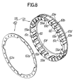
- a large number of rollers 60 are disposed between the cam grooves 58a and a roller abutment surface 52a around an outer periphery of the recess of the gear 521 and are retained by a retainer 59.
- the retainer 59 is a ring-like member relatively rotatably received in the recess of the gear 521 and comprised of two components, i.e., a body portion 61 and a cover plate 62.
- the body portion 61 is provided with roller retaining grooves 61b each defined between adjacent two of a large number of connections 61a to retain the roller 60 for slight movement in a radial direction.
- each of the roller retaining grooves 61b i.e., a surface opposed to the outer periphery of the roller 60, is formed by an arcuate surface having a radius of curvature larger than the radius of the roller 60, whereby the angle of a corner formed by the roller abutment surface 52a and the roller retaining groove 61b is acute.
- a projection 61c is formed on a side of the connection 61a.
- the body portion 61 and the cover plate 62 are integrally coupled with the rollers 60 retained therein by fitting the projections 61c into holes 62 a provided in the cover plate 62 in a caulking manner.
- roller ingress grooves 59a are provided around an inner periphery of the retainer 59 at 90° spacing to extend axially and open into the side of the retainer 59 closer to the cover plate 62.
- the formation of the roller retaining groove 61b by the arcuate surface as described above ensures that there is no possibility of the rollers 60 falling out of the roller 61b, leading to a substantially enhanced ability to assemble the retainer 59.
- the roller retaining groove 61b in the body portion 61 requiring the highest accuracy is opened to the joined surface of the cover plate 62 and therefore, the roller retaining groove 61b can be easily machined with a high degree of accuracy.
- Such retainer 59 is mounted between the roller abutment surface 52a around the outer periphery of the recess of the gear 52, and the cam surface 58a of the inner cam 58.
- a sliding-contact portion 61d adapted to be tightly fitted in the recess of the gear 521 is formed around the outer periphery of the body portion 61 of the retainer 59.
- a lubricating groove 61e is provided around the outer periphery of the body portion 61 of the retainer 59 and a retaining portion 611 is formed on the body portion 61 to abut against the side of the inner cam 58 in order to restrain the axial movement of the body portion 61.
- dowels 56a are provided on and project from the side of the sleeve 56 at a spacing of 90°, and they are engaged into and disengaged from the dowel ingress grooves 59a in the retainer 59 by axially moving the sleeve 56 through the spline 55.
- the inner cam 58 and the retainer 59 are located in their states shown in Fig.7, and the roller 60 is fitted in the center of the cam groove 58a.
- the structures of the retainer 59 and the inner cam 58 in the second to seventh gear trains G2 to G7 are substantially the same as those in the first gear train G1 and hence, the description thereof is omitted.
- a shift mechanism 63 for driving each of the roller synchro mechanisms S12 to S7 includes a cylindrical shift drum 64 disposed in parallel to and in proximity to upper portions of the main shaft 9 and the counter shaft 10.
- the shift drum 64 is comprised of a left half 67 supported by a ball bearing 65 mounted on the left casing 2 and a ball bearing 66 mounted on the body casing 1 and a right half 69 supported on the intermediate casing 3 with the ball bearing 68 interposed therebetween.
- the left and right halves 67 and 69 are coaxially coupled by a pin 70.
- a driving gear 73 is provided on an output shaft of a pulse motor 72 and is meshed with a follower gear 71 fixed the coupled portion between the halves 67 and 69 by the pin 70, so that the shift drum 64 is rotated accurately through predetermined angles.
- a boss portion 57a of the shift fork 57 is axially slidably carried on an outer periphery of the left half 67 of the shift drum 64 with a pair of slide bearings 74 interposed therebetween.
- a guide pin 75 is embedded radially inwardly in the boss portion 57a and fitted and guided into a cam groove 67a made in an outer periphery of the left half of the shift drum 64.
- a mechanism for driving each of the shift forks 57 of the three roller synchro mechanisms S34 to S7 mounted at the right half 69 of the shift drum 64 has substantially same structure as the mechanism for driving the shift fork 57 of the roller synchro mechanism S12 and hence, the repeated description thereof is omitted.
- the shapes of the cam grooves provided in the shift drum 64 to drive the shift forks 57 are different depending upon the individual shift stages.
- An increase in rigidity of the shift drum 64 and an improvement in the ability to assemble it can be provided by a construction such that the shift drum 64 is divided into two parts, i.e., the left half on the side of the first and second gear trains G1 and G2 and the right half 69 on the side of the third to seventh gear trains G3 to G7, and the left and right halves are integrally coupled by the pin 70.
- the gears 71 and 73 for driving the shift drum 64 are provided on an intermediate portion of the shift drum 64, the pulse motor 72 for driving the gears 71 and 73 can be received compactly within the width of the transmission casing without projecting sideways from the transmission casing.
- a reverse idle gear 82 carried on a reverse idle shaft 81 mounted above the main shaft 9 and the counter shaft 10 is meshed with a reverse input gear 79 provided on the main shaft 9 and a reverse output gear 80 provided on the counter shaft 10.
- the reverse idle shaft 81 is comprised of an inner shaft portion 83 axially slidably carried on the body casing 1, and an outer shaft portion 85 fitted over the inner shaft 84 and integrally coupled thereto by a pin 84 which is axially slidably engaged in a guide hole 2a provided in the left casing 2.
- the reverse idle gear 82 is carried on an inner periphery of the inner shaft portion 83 for nonmovement in an axial direction and for relative rotation.
- a follower gear 88 meshed with a driving gear 87 of a pulse motor 86 mounted on the left casing 2 is threadedly engaged with the outer periphery of the outer shaft portion 85 of the reverse idle shaft 81 through a truncated-conical screw.
- the outer shaft portion 85 which is threadedly engaged with the follower gear 88 and prevented from being rotated by the pin 84, is moved axially.
- the inner shaft portion 83 and the reverse idle gear 82 are also moved axially together with the outer shaft portion 85, and they are put into and out of engagement with the reverse input gear 79 on the main shaft 9 and the reverse output gear 80 on the counter shaft 10.
- the meshed state of the reverse idle gear 82 is detected from the axial position of the outer shaft portion 85 by a stroke sensor 89, thereby preventing a biting of the reverse idle gear 82 during idling.
- the reverse transmitting mechanism 90 having the above-described construction separately from the forward transmitting mechanism 63 in this manner, an improvement in reliability in the shifting operation can be provided.
- the two revolution speed sensors 44 and 49 for the main shaft 9 and the counter shaft 10 as well as the stroke sensor 89 are compactly disposed on the left casing 2, whereby the maintenance of them can be easily conducted.
- the clutch 21 is used only at the start of movement of the vehicle.
- the release piston 31 is moved rightwardly by a hydraulic pressure applied to the oil chamber 36 to urge the inner end of the diaphragm spring 35, the clutch disks 23 and 27 are moved away from one another to release the transmission of the driving force. If the clutch pedal is returned from this state, since the clutch disks 23 and 27 are brought into close contact with one another by the resilient force of the diaphragm spring 35, the clutch 21 is brought into its engaged state, thereby permitting the driving force from the crankshaft 14 to be transmitted to the transmission input shaft 15.
- the first to seventh shift stages and the reverse shift stage are selectively established by driving the pulse motors 72 and 86 on the basis of an electric signal converted from the shifting operation by the driver. For example, if an up-shifting command signal is produced, the engine throttle valve is controlled so that a revolution speed ratio of the shafts 9 and 10 is equal to a value determined from a reduction ratio of a shift stage to be established by up-shifting on the basis of the speed of rotation of the main shaft 9 detected by the revolution speed sensor 44 and the speed of rotation of the counter shaft 10 detected by the revolution speed sensor 49, thereby reducing the speed of rotation of the engine crankshaft.
- the shift mechanism 63 is driven to permit an up-shifting operation to be conducted. For example, if the up-shifting is conducted from the first shift to the second shift, then the pulse motor 72 is driven to rotate the shift drum 64 through a predetermined angle. This causes the shift fork 57 to be moved axially through the guide pin 75 which is engaged with the cam groove 67a provided in the outer periphery of the left half 67 of the shift drum 64 to couple the gear 522 of the second shift gear train G2 through the roller synchro mechanism S12 to the counter shaft 10, thereby establishing the second shift stage.
- the engine throttle valve is driven so that the speed of rotation of the main shaft 9 is likewise synchronized with the speed of rotation of the counter shaft 10, thereby increasing the speed of rotation of the engine crankshaft. Thereafter, the shift mechanism 63 is driven to establish the desired down-shift stage.
- roller synchro mechanisms S12 to S7 will be described below taking the first and second shift roller synchro mechanism S12 as an example.
- the inner cam 58 and the retainer 59 are located in their states shown in Fig.7.
- each of the rollers 60 retained by the retainer 59 is movable radially within the roller retaining groove 61b.
- the retainer 59 and the inner cam 58 are slightly rotated relative to each other by a torque applied thereto from the counter shaft 10 or the gear 521, thereby causing the rollers 60 to be powerfully urged radially outwardly within the roller retaining grooves 61b by the cam grooves 58a of the inner cam 58 and brought into pressure contact with the roller abutment surface of the gear 521.
- the body portion 61 of the retainer 59 is provided with the sliding-contact portion 61d which comes into close contact with the recess in the gear 521, and the retainer 59 is rotated in such a manner as to follow the gear 521 by a frictional force applied to the sliding-contact portion 61d, thus promptly coupling the gear 521 with the counter shaft 10.
- rollers 60 are brought into a free state within the roller retaining grooves 61b concurrently with the insertion of the dowels 56a, and the releasing of the engagement of the gear 521 with the counter shaft 10 is promptly conducted without a time lag.
- the reverse idle shaft 81 threadedly engaged with the follower gear 88 is retracted axially by rotating the follower gear 88 meshed with the driving gear 87 of the pulse motor 86.
- the rotation of the main shaft 9 is transmitted as a rotation in the same direction to the counter shaft 10 via the reverse input gear 79, the reverse idle gear 82 and the reverse output gear 80.
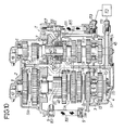
- a transmission T for a vehicle comprises a main case body 1 disposed in a longitudinal direction of the vehicle, i.e., in the lateral direction as viewed in Figs.9 and 10, a left case portion 2 coupled to a left side of the main case body 1, a right case portion 4 coupled to a right side of the main case body 1 through an intermediate case portion 3, and a rear case portion 5 coupled to a rear portion of the main case body 1.
- a main shaft 9 extending laterally of the vehicle is disposed to pass a left side wall of the main case body 1 at an intermediate portion in the longitudinal direction of the vehicle.
- a roller bearing 6 is interposed between one end of the main shaft 9 and the left case portion 2, and a ball bearing 7 is interposed between the left side wall of the main case body 1 and the main shaft 9.
- a roller bearing 8 is interposed between the intermediate case portion 3 and the main shaft 9.
- a counter shaft 10 having an axis parallel to the main shaft 9 is disposed rearwardly of add above the main shaft 9, and roller bearings 11, 12 and 13 are interposed between the counter shaft 10 and the left case portion 2, the main case body 1 and the intermediate case portion 3, respectively.
- a crankshaft 14 is disposed in a direction perpendicular to the main shaft 9 and the counter shaft 10, i.e., in the longitudinal direction of the vehicle and is connected at its rear end to a driving bevel gear 17 through a wet multi-plate clutch 21 which is disposed at a front portion of the main case portion 1.
- the driving bevel gear 17 is meshed with a follower bevel gear 41 provided on the main shaft 9.
- First to seventh shift gear trains G1 to G7 and a reverse gear train G R are provided between the main shaft 9 and the counter shaft 10 and arranged in such manner that the first and second gear trains G1 and G2 and the reverse gear train G R are located between the main case body 1 and the left case portion 2, while the third to sixth gear trains G3 to G6 are located between the main case body 1 and the intermediate case portion 3, and the seventh shift gear train G7 is located between the intermediate case portion 3 and the right case portion 4.
- the maintenance of the first and second gear trains G1 and G2 and the reverse gear train G R can be conducted merely by removing the left case portion 2 from the main case body 1, and the maintenance of the third to seventh shift gear trains G3 to G6 can be conducted by removing the intermediate case portion 3 or the right case portion 4 from the main case body 1.
- Gears in the first to seventh shift gear trains G1 to G7 on the side of the main shaft 9 are fixed to the main shaft 9, whereas gears on the side of the counter shaft 10 are connected to the counter shaft 10 through roller synchro mechanisms S12, S34, S56 and S7, and one of the gear trains G1 to G7 is selectively established by operation of the individual synchro mechanism S12, S34, S56, S7.
- An idle gear which is not shown is disposed at an intermediate portion of the reverse gear train G R , and the reverse gear train G R is established by driving the idle gear by a means similar to the first embodiment but which is not shown here.
- a revolution speed sensor 44 is mounted on the left case portion 2 and connected the left end (an upper end as viewed in Fig.10) of the main shaft 9, and a starting gear 45 is provided at the right end of the main shaft 9 and connected to a starting motor which is not shown.
- An output gear 46 is provided on the counter shaft 10 to lie between the left side wall of the main case body 1 and the third gear train G3 and is meshed with an input gear 48 of a conventional differential 47.
- a revolution speed sensor 49 is mounted on the left case portion 2 and connected to the left end of the counter shaft 10.
- a bottom 1a of the main case body 1 and a bottom 5a of the rear case portion 5 in the transmission T are formed so that they are connected to each other and inclined downwardly in the forward direction of the vehicle (in the rightward direction as viewed in Fig.9).
- a lubricating oil is stored in the oil reservoir R in an amount sufficient to provide an oil level L slightly lower than the axis of the crankshaft 14 in a condition in which the vehicle is travelling on a horizontal road surface at a cruising speed.
- Pumps 42 and 43 are disposed side by side in an axial direction of the main shaft 9 between the third shift gear train G3 and the follower bevel gear 41 and are driven by the main shaft 9.
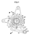
- the pumps 42 and 43 are roller vane pumps juxtaposed in a tandem fashion in a common casing 129 which is supported on the main case body 1 of the transmission T.
- the casing 129 is comprised of a case portion 130 fastened to the main case body 1 by a plurality of bolts 167, and a cover 131 coupled to the case portion 130.
- the case portion 130 is provided, in sequence from the side of the cover 131, with a large diameter hole 132 and a small diameter hole 133 connected the large diameter hole 132 through a step 134.
- the large diameter hole 133 is made eccentrically by a distance E from the center of the small diameter hole 133 along one diametrical line 135 of the small diameter hole 133.
- the cover 131 is also provided at its central portion with a hole 136 substantially corresponding to the small diameter hole 133.
- a left sliding-contact plate 137 Received in the larger diameter hole 132 in sequence from the side of the step 134 are a left sliding-contact plate 137, a left ring 138, a partition plate 139 and a right ring 140.
- the case portion 130 and the cover 131 are fastened together by a plurality of threaded members 92 to sandwich a right sliding-contact plate 91 therebetween, thereby ensuring that the left sliding-contact plate 137, the left ring 138, the partition plate 139, the right ring 140 and the right sliding-contact plate 91 are fixedly clamped between the case portion 130 and the cover 131.
- Inner peripheries of the sliding-contact plates 137 and 91 and the partition plate 139 substantially correspond to the smaller diameter hole 133.
- a left rotor 93 is slidably clamped between the left sliding-contact plate 137 and the partition plate 139, and a right rotor 94 is slidably clamped between the partition plate 139 and the right sliding-contact plate 91.
- Each of the rotors 93 and 94 is formed into a ring-like shape coaxial with the main shaft 9 and has an inner periphery coupled to a ring-like hub 95 through a spline 96.
- An inner periphery of the hub 95 is coupled through a spline 97 to an outer periphery of the main shaft portion 9 passed through the casing 129.
- the rotors 93 and 94 are provided respectively with pluralities of guide grooves 98 and 99 extending radially at circumferentially spaced apart locations and opened at their outer ends and rollers 150 and 151 are received in the guide grooves 98 and 99, respectively.
- Annular communication grooves 152 and 153 are provided in opposite surfaces of the corresponding rotors 93 and 94 for each connecting inner ends of adjacent two of the corresponding guide grooves 98 and 99 to each other.
- Pump chambers 180 and 181 are defined between the rings 138 and 140 received in the larger diameter hole 132 and the rotors 143 and 144, respectively.
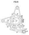
- the width of each of the pump chambers 180 and 181 is gradually varied in a rotational direction 182 indicated by an arrow in Fig. 11 by reason of the fact that the rings 138 and 140 and the rotors 93 and 94 are eccentric. More specifically, the width of the pump chamber 180, 181 is gradually increased in a range of 180 degrees in the rotational direction 182 from a minimum position P1 defined on the above-described one diametrical line 135 and gradually decreased in a range of 180 degrees from a maximum position P2 to the minimum position P1.
- the rollers 150 and 151 are rolled along inner surfaces of the rings 138 and 140 in response to the rotation of the rotors 93 and 94, respectively, the lubricating oil is drawn into the pump chambers 180 and 181 in their sections from the minimum position P1 to the maximum position P2, and gradually compressed in sections from the maximum position P2 to the minimum position P1.
- Arcuate grooves are provided in the step 134 of the case portion 130 on opposite sides of the one diametrical line 135 and define an inlet oil passage 154 and an outlet oil passage 155 in cooperation with the left sliding-contact plate 137.
- the inlet oil passage 154 communicates with the section of the pump chamber 180 from the minimum position P1 to the maximum position P2 in the rotational direction 182, while the outlet oil passage 155 communicates with the section of the pump chamber 180 from the maximum position P2 to the minimum position P1 in the rotational direction 182.
- an arcuate inlet oil passage 156 and an arcuate outlet oil passage 157 are provided between the cover 131 and the right sliding-contact plate 91, respectively.
- the inlet oil passage 156 communicates with the section of the pump chamber 181 from the minimum position P1 to the maximum position P2 in the rotational direction 182, while the outlet oil passage 157 communicates with the section of the pump chamber 181 from the maximum position P2 to the minimum position P1 in the rotational direction 182.
- the case portion 130 is provided with an intake port 160 leading to the inlet oil passage 154, a discharge port 161 leading to the outlet oil passage 155, and an intake port 162 leading to the inlet oil passage 156.
- the cover 131 is provided with a discharge port 163 leading to the outlet oil passage 157.
- the discharge ports 161 and 163 communicate with each other through a communication hole 171 provided in the right sliding-contact plate 91.
- the pump 42 is constructed on the left side of the casing 129, while the pump 43 is constructed on the right side of the casing 129, so that the pumps 42 and 42 are operated in response to the rotation of the main shaft 9.
- a strainer 165 is disposed in a portion of the oil reservoir R in front of the pumps 42 and 43 within the transmission T and located below the oil level L, and a strainer 166 is disposed in a portion of the oil reservoir R to the rear of the pumps 42 and 43 at a location substantially corresponding to the oil level L.
- the strainers 165 and 166 are cylindrically shaped to extend in parallel to the axis of the main shaft 9.
- One end of the strainer 165 is fitted into an insert hole 168 which is provided in the case portion 130 to insert a bolt 167 for fastening the case portion 130 to the main case body 1, and the other end is threadedly received into the right side wall of the main case body 1.
- One end of the strainer 166 is fitted into a fitting hole 169 provided in the left side wall of the rear case portion 5, and the other end is threadedly received into the right side wall of the rear case portion 5.
- the end of the strainer 165 that is fitted into the insert hole 68 is connected to the intake port 160 of the pump 42, and the lubricating oil filtered by the strainer 165 is drawn by the pump 42.
- One end of an intake pipe 170 is connected to end of the strainer 166 and the other end of the intake pipe 170 is connected to the intake port 162 of the pump 43.
- the lubricating oil filtered by the strainer 166 is drawn by the pump 43.
- a discharge pipe 172 is provided to extend between the case portion 132 and the right side wall of the main case body 1 and is connected at one end thereof to the discharge port 163 in communication with the discharge port 161 through the communication hole 171 and at the other end thereof to an oil cooler 173 through a connecting pipe 178.
- the oil cooler 173 is connected through a connecting pipe 179 to an oil passage 174 which is provided in the right case 4.
- an oil supply passage 175 for supplying a lubricating oil to each of the synchro mechanisms S12, S34, S56 and S7 mounted on the counter shaft 10.
- the oil supply passage 175 communicates with the oil passage 174.
- a further oil supply passage 176 is provided to extend between the left case portion 2 and the right case portion 4 and to pass through the left side wall of the main case body 1 above the meshed-engagement of the gears in the gear trains G1 to G7 and G R and is connected to the oil passage 174. Moreover, the oil supply passage 176 is provided with a plurality of ejection holes 177 for ejecting the lubricating oil toward such meshed gears.
- both the pumps 42 and 43 are operated in response to the rotation of the main shaft 9 which is operatively connected to the crankshaft 14, and the lubricating oil stored in the oil reservoir R is filtered in the strainers 165 and 166 and drawn into the pumps 42 and 43.
- the lubricating oil discharged from the pumps 42 and 43 is cooled in the oil cooler 173 and then supplied from the oil passage 174 via the oil supply passage 175 to the lubricated portions of the synchro mechanisms S12, S34, S56 and S7 and ejected from the plurality of ejection holes 177 in the oil supply pipe 176 to the meshed portions of the gears in the gear trains G1 to G7 and G R .
- the oil level L is kept substantially constant, and at least a portion of each of the strainers 165 and 166 is immersed in the lubricating oil, therefore, lubricating oil filtered in the strainers 165 and 166 can be supplied to each of the portions which are to be lubricated.
- the lubricating oil in the oil reservoir R may be moved rearwardly, resulting in an absence of the lubricating oil around the front strainer 165 which is located at the front end.
- the strainer 166 is located at the rear end and reliably immersed in the lubricating oil, when the lubricating oil is moved rearwardly, the lubricating oil can be drawn into the pump through the strainer 166. During a rapid decrease in the speed of the vehicle, the lubricating oil in the oil reservoir R is moved forwardly, ensuring that the lubricating oil can be reliably drawn into the pump 42 through the strainer 165 which is located in the front end.
- roller synchro mechanisms have been described as being used in the transmission of the first embodiment, any other synchro mechanism can be used in place of the roller synchro mechanisms.
- a different type of clutch can be used in place of the wet multi-plate clutch 21 .
- the strainers 165 and 166 have been disposed at a distance from each other in the longitudinal direction of the vehicle, a pair of strainers can be disposed at different levels in a lateral direction of the vehicle to provide for a continuous supply of oil during cornering of the vehicle.
Landscapes
- Engineering & Computer Science (AREA)
- General Engineering & Computer Science (AREA)
- Mechanical Engineering (AREA)
- Chemical & Material Sciences (AREA)
- Combustion & Propulsion (AREA)
- Transportation (AREA)
- Structure Of Transmissions (AREA)
Applications Claiming Priority (4)
| Application Number | Priority Date | Filing Date | Title |
|---|---|---|---|
| JP2336578A JPH04203642A (ja) | 1990-11-30 | 1990-11-30 | 車両用多段変速機 |
| JP336584/90 | 1990-11-30 | ||
| JP336578/90 | 1990-11-30 | ||
| JP33658490A JPH04203657A (ja) | 1990-11-30 | 1990-11-30 | 車両用変速機の給油装置 |
Publications (3)
| Publication Number | Publication Date |
|---|---|
| EP0490548A2 true EP0490548A2 (de) | 1992-06-17 |
| EP0490548A3 EP0490548A3 (en) | 1992-09-16 |
| EP0490548B1 EP0490548B1 (de) | 1996-04-03 |
Family
ID=26575519
Family Applications (1)
| Application Number | Title | Priority Date | Filing Date |
|---|---|---|---|
| EP91311161A Expired - Lifetime EP0490548B1 (de) | 1990-11-30 | 1991-11-29 | Kraftübertragung für ein Fahrzeug |
Country Status (3)
| Country | Link |
|---|---|
| US (1) | US5181893A (de) |
| EP (1) | EP0490548B1 (de) |
| DE (1) | DE69118491T2 (de) |
Cited By (5)
| Publication number | Priority date | Publication date | Assignee | Title |
|---|---|---|---|---|
| WO2006002736A1 (de) * | 2004-06-30 | 2006-01-12 | Zf Friedrichshafen Ag | Ölversorgungseinrichtung |
| WO2008011943A1 (de) * | 2006-07-24 | 2008-01-31 | Magna Powertrain Ag & Co Kg | Getriebe |
| US9506504B2 (en) | 2013-08-27 | 2016-11-29 | Borgwarner Inc. | Lubrication in a transfer case without a mechanical pump |
| US9752671B2 (en) | 2014-02-21 | 2017-09-05 | Borgwarner Inc. | Transfer case—method of controlling lubrication—eco— mode operation |
| CN109469688A (zh) * | 2018-11-27 | 2019-03-15 | 常州金坛群英机械有限公司 | 一种离合器装置 |
Families Citing this family (7)
| Publication number | Priority date | Publication date | Assignee | Title |
|---|---|---|---|---|
| EP1132661B1 (de) * | 2000-03-10 | 2004-03-17 | Honda Giken Kogyo Kabushiki Kaisha | Verfahren und Vorrichtung zur Steuerung einer Gangschaltung mit elektrischer Schaltwalze |
| US7896120B2 (en) * | 2008-04-02 | 2011-03-01 | Yamaha Hatsudoki Kabushiki Kaisha | Small-sized vehicle with improved drivetrain |
| CN102661363B (zh) * | 2012-05-10 | 2015-01-07 | 中信机电制造公司科研设计院 | 用于重型车辆的传动箱 |
| CN104781592B (zh) * | 2012-09-10 | 2017-08-22 | Dti集团有限公司 | 用于车辆的驱动系统 |
| CN209654588U (zh) | 2019-01-29 | 2019-11-19 | 浙江春风动力股份有限公司 | 一种变速鼓、发动机及摩托车 |
| CN209524062U (zh) | 2019-01-29 | 2019-10-22 | 浙江春风动力股份有限公司 | 一种花键齿、齿轮接合机构及变速箱 |
| CN110671487B (zh) * | 2019-09-30 | 2023-03-14 | 重庆长安汽车股份有限公司 | 一种混动变速器的中连板及汽车 |
Family Cites Families (10)
| Publication number | Priority date | Publication date | Assignee | Title |
|---|---|---|---|---|
| DE133077C (de) * | ||||
| US662400A (en) * | 1899-04-26 | 1900-11-27 | Frank L Dyer | Gearing for-automobile vehicles. |
| US635171A (en) * | 1899-06-30 | 1899-10-17 | Louis Mathieu | Driving-gear for motor-vehicles. |
| US1652358A (en) * | 1922-04-13 | 1927-12-13 | Rock Island Plow Co | Tractor |
| US2717521A (en) * | 1953-02-18 | 1955-09-13 | Goodman Mfg Co | Transmission for mine vehicles |
| US3095759A (en) * | 1961-03-31 | 1963-07-02 | J T Herrod | Combination transmission and differential |
| DE2722902A1 (de) * | 1977-05-20 | 1978-11-23 | Volkswagenwerk Ag | Fahrzeug, insbesondere frontgetriebenes personenkraftfahrzeug |
| DE3143301A1 (de) * | 1981-10-31 | 1983-05-11 | Hermann Dr.-Ing. 7412 Eningen Klaue | Gleichachsiges schalt- und achsgetriebe, insbesondere fuer kraftfahrzeuge |
| JPH077652Y2 (ja) * | 1986-08-08 | 1995-02-22 | 本田技研工業株式会社 | 後進機構付き変速装置 |
| DE3925409A1 (de) * | 1989-08-01 | 1991-02-07 | Getrag Getriebe Zahnrad | Kraftfahrzeug |
-
1991
- 1991-11-27 US US07/799,548 patent/US5181893A/en not_active Expired - Fee Related
- 1991-11-29 EP EP91311161A patent/EP0490548B1/de not_active Expired - Lifetime
- 1991-11-29 DE DE69118491T patent/DE69118491T2/de not_active Expired - Fee Related
Cited By (6)
| Publication number | Priority date | Publication date | Assignee | Title |
|---|---|---|---|---|
| WO2006002736A1 (de) * | 2004-06-30 | 2006-01-12 | Zf Friedrichshafen Ag | Ölversorgungseinrichtung |
| WO2008011943A1 (de) * | 2006-07-24 | 2008-01-31 | Magna Powertrain Ag & Co Kg | Getriebe |
| US8650980B2 (en) | 2006-07-24 | 2014-02-18 | Magna Powertrain Ag & Co Kg | Transmission |
| US9506504B2 (en) | 2013-08-27 | 2016-11-29 | Borgwarner Inc. | Lubrication in a transfer case without a mechanical pump |
| US9752671B2 (en) | 2014-02-21 | 2017-09-05 | Borgwarner Inc. | Transfer case—method of controlling lubrication—eco— mode operation |
| CN109469688A (zh) * | 2018-11-27 | 2019-03-15 | 常州金坛群英机械有限公司 | 一种离合器装置 |
Also Published As
| Publication number | Publication date |
|---|---|
| EP0490548A3 (en) | 1992-09-16 |
| DE69118491D1 (de) | 1996-05-09 |
| US5181893A (en) | 1993-01-26 |
| EP0490548B1 (de) | 1996-04-03 |
| DE69118491T2 (de) | 1996-08-01 |
Similar Documents
| Publication | Publication Date | Title |
|---|---|---|
| JP3853963B2 (ja) | パワーユニット | |
| JP3748755B2 (ja) | 四輪駆動車両の動力伝達装置 | |
| EP0490548B1 (de) | Kraftübertragung für ein Fahrzeug | |
| US6749530B2 (en) | Belt-type continuously variable transmission | |
| US7866227B2 (en) | Vehicular power transmission system | |
| US4924989A (en) | Automatic clutch control system for coupling two rotating shafts | |
| CA2322104C (en) | Motive-power transmission device for vehicle | |
| US5720372A (en) | Lubricating structure of hydraulic clutch | |
| JPH05141441A (ja) | 変速機構 | |
| JPS5899548A (ja) | ベルト式無段変速機 | |
| JP4318822B2 (ja) | 無段変速機用潤滑油給油装置 | |
| EP0851149B1 (de) | Planetengetriebe | |
| CA2277195C (en) | Reversible variable speed transmission and transaxle having pressure compensating flow metering device | |
| US5480361A (en) | Change direction planetary gearing for continuously variable transmission | |
| JP4198385B2 (ja) | 多板式自動遠心クラッチ装置 | |
| JP3748680B2 (ja) | 無段変速機の潤滑構造 | |
| JP2629374B2 (ja) | 遊星歯車装置 | |
| JP2581965B2 (ja) | 動力伝達装置 | |
| JP3853964B2 (ja) | パワーユニットにおける無段変速機の潤滑構造 | |
| JP2001099276A (ja) | トロイダル型無段変速機のアイドラベアリング潤滑構造 | |
| JPH0620829B2 (ja) | 車両用動力伝達装置 | |
| JP2002228089A (ja) | 潤滑油路構造 | |
| JP2652673B2 (ja) | 4輪駆動車の動力分配装置 | |
| JP3608683B2 (ja) | 作業車両の動力取出装置 | |
| JP3990500B2 (ja) | 作業車両の前輪駆動力取出し装置 |
Legal Events
| Date | Code | Title | Description |
|---|---|---|---|
| PUAI | Public reference made under article 153(3) epc to a published international application that has entered the european phase |
Free format text: ORIGINAL CODE: 0009012 |
|
| AK | Designated contracting states |
Kind code of ref document: A2 Designated state(s): DE FR GB IT |
|
| PUAL | Search report despatched |
Free format text: ORIGINAL CODE: 0009013 |
|
| 17P | Request for examination filed |
Effective date: 19920704 |
|
| AK | Designated contracting states |
Kind code of ref document: A3 Designated state(s): DE FR GB IT |
|
| 17Q | First examination report despatched |
Effective date: 19940511 |
|
| GRAH | Despatch of communication of intention to grant a patent |
Free format text: ORIGINAL CODE: EPIDOS IGRA |
|
| GRAA | (expected) grant |
Free format text: ORIGINAL CODE: 0009210 |
|
| AK | Designated contracting states |
Kind code of ref document: B1 Designated state(s): DE FR GB IT |
|
| PG25 | Lapsed in a contracting state [announced via postgrant information from national office to epo] |
Ref country code: IT Free format text: LAPSE BECAUSE OF FAILURE TO SUBMIT A TRANSLATION OF THE DESCRIPTION OR TO PAY THE FEE WITHIN THE PRE;WARNING: LAPSES OF ITALIAN PATENTS WITH EFFECTIVE DATE BEFORE 2007 MAY HAVE OCCURRED AT ANY TIME BEFORE 2007. THE CORRECT EFFECTIVE DATE MAY BE DIFFERENT FROM THE ONE RECORDED.SCRIBED TIME-LIMIT Effective date: 19960403 Ref country code: FR Effective date: 19960403 |
|
| REF | Corresponds to: |
Ref document number: 69118491 Country of ref document: DE Date of ref document: 19960509 |
|
| EN | Fr: translation not filed | ||
| PLBE | No opposition filed within time limit |
Free format text: ORIGINAL CODE: 0009261 |
|
| STAA | Information on the status of an ep patent application or granted ep patent |
Free format text: STATUS: NO OPPOSITION FILED WITHIN TIME LIMIT |
|
| 26N | No opposition filed | ||
| PGFP | Annual fee paid to national office [announced via postgrant information from national office to epo] |
Ref country code: GB Payment date: 19981204 Year of fee payment: 8 |
|
| PG25 | Lapsed in a contracting state [announced via postgrant information from national office to epo] |
Ref country code: GB Free format text: LAPSE BECAUSE OF NON-PAYMENT OF DUE FEES Effective date: 19991129 |
|
| PGFP | Annual fee paid to national office [announced via postgrant information from national office to epo] |
Ref country code: DE Payment date: 19991129 Year of fee payment: 9 |
|
| GBPC | Gb: european patent ceased through non-payment of renewal fee |
Effective date: 19991129 |
|
| PG25 | Lapsed in a contracting state [announced via postgrant information from national office to epo] |
Ref country code: DE Free format text: LAPSE BECAUSE OF NON-PAYMENT OF DUE FEES Effective date: 20010801 |