EP0492876B1 - Rampe d'alimentation en carburant - Google Patents
Rampe d'alimentation en carburant Download PDFInfo
- Publication number
- EP0492876B1 EP0492876B1 EP91311433A EP91311433A EP0492876B1 EP 0492876 B1 EP0492876 B1 EP 0492876B1 EP 91311433 A EP91311433 A EP 91311433A EP 91311433 A EP91311433 A EP 91311433A EP 0492876 B1 EP0492876 B1 EP 0492876B1
- Authority
- EP
- European Patent Office
- Prior art keywords
- fuel
- assemblies
- assembly
- core
- fuel rail
- Prior art date
- Legal status (The legal status is an assumption and is not a legal conclusion. Google has not performed a legal analysis and makes no representation as to the accuracy of the status listed.)
- Expired - Lifetime
Links
- 239000000446 fuel Substances 0.000 title claims description 286
- 230000000712 assembly Effects 0.000 claims description 44
- 238000000429 assembly Methods 0.000 claims description 44
- 238000000034 method Methods 0.000 claims description 25
- 238000002347 injection Methods 0.000 claims description 13
- 239000007924 injection Substances 0.000 claims description 13
- 239000002991 molded plastic Substances 0.000 claims description 9
- 230000008878 coupling Effects 0.000 claims description 6
- 238000010168 coupling process Methods 0.000 claims description 6
- 238000005859 coupling reaction Methods 0.000 claims description 6
- 238000000465 moulding Methods 0.000 claims description 6
- 239000004033 plastic Substances 0.000 claims description 6
- 238000007789 sealing Methods 0.000 claims description 6
- XUIMIQQOPSSXEZ-UHFFFAOYSA-N Silicon Chemical compound [Si] XUIMIQQOPSSXEZ-UHFFFAOYSA-N 0.000 claims description 4
- 229910052710 silicon Inorganic materials 0.000 claims description 4
- 239000010703 silicon Substances 0.000 claims description 4
- 238000013459 approach Methods 0.000 description 11
- 238000004519 manufacturing process Methods 0.000 description 8
- 238000009966 trimming Methods 0.000 description 8
- 238000001746 injection moulding Methods 0.000 description 5
- 238000003754 machining Methods 0.000 description 5
- 238000012360 testing method Methods 0.000 description 5
- 238000002485 combustion reaction Methods 0.000 description 4
- 238000002788 crimping Methods 0.000 description 4
- 238000005260 corrosion Methods 0.000 description 3
- 230000007797 corrosion Effects 0.000 description 3
- 238000005259 measurement Methods 0.000 description 3
- 238000012545 processing Methods 0.000 description 3
- 239000000523 sample Substances 0.000 description 3
- 238000004891 communication Methods 0.000 description 2
- 238000003780 insertion Methods 0.000 description 2
- 230000037431 insertion Effects 0.000 description 2
- 238000009434 installation Methods 0.000 description 2
- 239000000463 material Substances 0.000 description 2
- 230000013011 mating Effects 0.000 description 2
- 239000003990 capacitor Substances 0.000 description 1
- 238000001816 cooling Methods 0.000 description 1
- 230000000694 effects Effects 0.000 description 1
- 238000001914 filtration Methods 0.000 description 1
- 238000011010 flushing procedure Methods 0.000 description 1
- 239000002828 fuel tank Substances 0.000 description 1
Images

Classifications
-
- F—MECHANICAL ENGINEERING; LIGHTING; HEATING; WEAPONS; BLASTING
- F02—COMBUSTION ENGINES; HOT-GAS OR COMBUSTION-PRODUCT ENGINE PLANTS
- F02D—CONTROLLING COMBUSTION ENGINES
- F02D41/00—Electrical control of supply of combustible mixture or its constituents
- F02D41/30—Controlling fuel injection
- F02D41/3005—Details not otherwise provided for
-
- F—MECHANICAL ENGINEERING; LIGHTING; HEATING; WEAPONS; BLASTING
- F02—COMBUSTION ENGINES; HOT-GAS OR COMBUSTION-PRODUCT ENGINE PLANTS
- F02M—SUPPLYING COMBUSTION ENGINES IN GENERAL WITH COMBUSTIBLE MIXTURES OR CONSTITUENTS THEREOF
- F02M51/00—Fuel-injection apparatus characterised by being operated electrically
- F02M51/005—Arrangement of electrical wires and connections, e.g. wire harness, sockets, plugs; Arrangement of electronic control circuits in or on fuel injection apparatus
-
- F—MECHANICAL ENGINEERING; LIGHTING; HEATING; WEAPONS; BLASTING
- F02—COMBUSTION ENGINES; HOT-GAS OR COMBUSTION-PRODUCT ENGINE PLANTS
- F02M—SUPPLYING COMBUSTION ENGINES IN GENERAL WITH COMBUSTIBLE MIXTURES OR CONSTITUENTS THEREOF
- F02M51/00—Fuel-injection apparatus characterised by being operated electrically
- F02M51/06—Injectors peculiar thereto with means directly operating the valve needle
- F02M51/061—Injectors peculiar thereto with means directly operating the valve needle using electromagnetic operating means
- F02M51/0625—Injectors peculiar thereto with means directly operating the valve needle using electromagnetic operating means characterised by arrangement of mobile armatures
- F02M51/0664—Injectors peculiar thereto with means directly operating the valve needle using electromagnetic operating means characterised by arrangement of mobile armatures having a cylindrically or partly cylindrically shaped armature, e.g. entering the winding; having a plate-shaped or undulated armature entering the winding
- F02M51/0671—Injectors peculiar thereto with means directly operating the valve needle using electromagnetic operating means characterised by arrangement of mobile armatures having a cylindrically or partly cylindrically shaped armature, e.g. entering the winding; having a plate-shaped or undulated armature entering the winding the armature having an elongated valve body attached thereto
- F02M51/0675—Injectors peculiar thereto with means directly operating the valve needle using electromagnetic operating means characterised by arrangement of mobile armatures having a cylindrically or partly cylindrically shaped armature, e.g. entering the winding; having a plate-shaped or undulated armature entering the winding the armature having an elongated valve body attached thereto the valve body having cylindrical guiding or metering portions, e.g. with fuel passages
- F02M51/0678—Injectors peculiar thereto with means directly operating the valve needle using electromagnetic operating means characterised by arrangement of mobile armatures having a cylindrically or partly cylindrically shaped armature, e.g. entering the winding; having a plate-shaped or undulated armature entering the winding the armature having an elongated valve body attached thereto the valve body having cylindrical guiding or metering portions, e.g. with fuel passages all portions having fuel passages, e.g. flats, grooves, diameter reductions
-
- F—MECHANICAL ENGINEERING; LIGHTING; HEATING; WEAPONS; BLASTING
- F02—COMBUSTION ENGINES; HOT-GAS OR COMBUSTION-PRODUCT ENGINE PLANTS
- F02M—SUPPLYING COMBUSTION ENGINES IN GENERAL WITH COMBUSTIBLE MIXTURES OR CONSTITUENTS THEREOF
- F02M61/00—Fuel-injectors not provided for in groups F02M39/00 - F02M57/00 or F02M67/00
- F02M61/16—Details not provided for in, or of interest apart from, the apparatus of groups F02M61/02 - F02M61/14
- F02M61/168—Assembling; Disassembling; Manufacturing; Adjusting
-
- F—MECHANICAL ENGINEERING; LIGHTING; HEATING; WEAPONS; BLASTING
- F02—COMBUSTION ENGINES; HOT-GAS OR COMBUSTION-PRODUCT ENGINE PLANTS
- F02M—SUPPLYING COMBUSTION ENGINES IN GENERAL WITH COMBUSTIBLE MIXTURES OR CONSTITUENTS THEREOF
- F02M69/00—Low-pressure fuel-injection apparatus ; Apparatus with both continuous and intermittent injection; Apparatus injecting different types of fuel
- F02M69/46—Details, component parts or accessories not provided for in, or of interest apart from, the apparatus covered by groups F02M69/02 - F02M69/44
- F02M69/462—Arrangement of fuel conduits, e.g. with valves for maintaining pressure in the pipes after the engine being shut-down
- F02M69/465—Arrangement of fuel conduits, e.g. with valves for maintaining pressure in the pipes after the engine being shut-down of fuel rails
-
- F—MECHANICAL ENGINEERING; LIGHTING; HEATING; WEAPONS; BLASTING
- F02—COMBUSTION ENGINES; HOT-GAS OR COMBUSTION-PRODUCT ENGINE PLANTS
- F02D—CONTROLLING COMBUSTION ENGINES
- F02D2400/00—Control systems adapted for specific engine types; Special features of engine control systems not otherwise provided for; Power supply, connectors or cabling for engine control systems
- F02D2400/21—Engine cover with integrated cabling
-
- F—MECHANICAL ENGINEERING; LIGHTING; HEATING; WEAPONS; BLASTING
- F02—COMBUSTION ENGINES; HOT-GAS OR COMBUSTION-PRODUCT ENGINE PLANTS
- F02M—SUPPLYING COMBUSTION ENGINES IN GENERAL WITH COMBUSTIBLE MIXTURES OR CONSTITUENTS THEREOF
- F02M55/00—Fuel-injection apparatus characterised by their fuel conduits or their venting means; Arrangements of conduits between fuel tank and pump F02M37/00
- F02M55/02—Conduits between injection pumps and injectors, e.g. conduits between pump and common-rail or conduits between common-rail and injectors
- F02M55/025—Common rails
Definitions
- the field of the invention relates to electromagnetic fuel injectors, fuel rails and processes for fabricating same.
- each fuel injector coupled to the fuel rail must deliver substantially the same amount of fuel during the predetermined time of actuation.
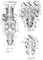
- Fuel injector 10 which is one of a plurality of fuel injectors connected to fuel rail 4, includes housing 12 constructed of an electromagnetic permeable material and having a lower housing 14 crimped to an upper housing 16.
- Lower housing 14 is fabricated by a conventional cold heading and machining process which forms fuel passageway 18 and cavity 20 for receiving coil bobbin assembly 22 therein.
- Electrical contacts 24 are positioned through plastic cap 26 and connected to coil bobbin assembly 22 through housing 12. Placement of "O" ring 28 and "O" ring 30 on respective lower housing 14 and upper housing 16 within cavity 20 is required to seal coil bobbin assembly 22 and electrical contacts 24 from fuel passageway 18.
- armature 34 is slidably, axially mounted within fuel passageway 18 and biased against spring 32.
- Armature 34 is connected to stem 36 which is axially positioned within sleeve 42 and includes conical end 38.
- Lower housing 14 is crimped to sleeve 42.
- Sleeve 42 has a conical seat 46 formed around valve opening 50 for mating with conical end 38 of stem 36 thereby forming a needle and seat valve.
- Fuel passageway 18 communicates with sleeve 42 and extends through upper housing 16 to fuel connector 6 which mates with fuel rail 4.
- coil bobbin assembly 22 is electrically actuated by a drive signal of predetermined voltage and pulse width.
- a magnetic field is thereby induced through a magnetic core defined by lower housing 14 and upper housing 16. This induced magnetic field couples to armature 34 deflecting it against spring 32 thereby opening the needle and seat valve.
- spring 32 downwardly deflects armature 34 thereby closing the needle and seat valve.
- dynamic fuel flow through the fuel injector is related to spring strength of spring 32, electrical characteristics of coil bobbin assembly 32, and size of valve opening 50.
- Tube 56 is inserted within fuel passageway 58 against spring 32 of prior art fuel injector 12 or similar fuel injector. Fuel injector 12 is then inserted on a test stand (not shown) and tube 56 connected to a stepper motor (not shown) for coupling axial movement to tube 56. A fuel metering probe (not shown) is coupled to fuel passageway 58 which in turn is coupled to a source of pressurised fuel (not shown). A voltage signal is then applied to electrical contacts 24 for a predetermined time and fuel flow measured. Tube 56 is axially displaced, upwardly or downwardly, until a desired fuel flow is measured during such predetermined time.
- tube 56 is crimped to prevent further movement.
- the spring constant of spring 32 is being adjusted to achieve a desired dynamic response.
- a set of closely matched fuel injectors are selected for installation on a particular fuel rail.
- a fuel distributor for fuel injection systems in internal combustion engines.
- the fuel distributor includes an elongated housing provided with axially spaced chambers each of which accommodates a fuel injection valve.
- a fuel line communicates with the chambers of the housing to supply fuel which flows around the valves to ensure both fuel supply and cooling.
- Flow diaphragms are also provided to provide forced flushing of the fuel injection valves.
- the inventor herein has recognised numerous disadvantages of the prior art device and processes described above.
- the fuel adjusting and fuel injector matching processes have inherent inaccuracies in addition to manufacturing complexity.
- a number of test stands are required for efficient manufacturing and each of these stands is calibrated differently. Accordingly, there will be variances between fuel injectors processed on different stands.
- the measuring probe influences fuel flow through each injector such that the resulting measurements may not accurately reflect actual fuel flow.
- only the injectors are adjusted and measured, fuel flow variances are also introduced by the fuel rail.
- the inventor herein has also recognised numerous disadvantages of the prior art structural devices, specifically the fuel injector and fuel rail. Numerous processing and assembly steps are required to fabricate a fuel rail and couple each individual fuel injector to the fuel rail through a corresponding fuel connector. Further, for each fuel injector, several "O" rings and corresponding assembly steps are required to seal coil bobbin assembly 22 and electrical contacts 24 from fuel passageway 18. In addition, complicated processing steps are required such as cold heading and machining lower housing 12 to form fuel passageway 18 and cavity 20. Cumbersome crimping steps are also required to assemble lower housing 12 to upper housing 14 and sleeve 42. The magnetically permeable housing is also susceptible to corrosion in typical under hood environments.
- An object of the invention described herein is to provide a fuel rail, including injectors, which are electrically tuned to deliver substantially the same amount of fuel from each injector. Another object is to eliminate the need for a fuel rail which is totally separate from the fuel injectors and eliminate the fuel connectors of prior approaches.
- a fuel rail assembly comprises: a plurality of fuel injectors each including an electric coil assembly and valve means mechanically responsive to application of electrical power to the coil assembly for controlling fuel flow through the fuel injector; a plurality of electronic drivers each coupled to a corresponding one of the electric coil assemblies for applying the electrical power; characterised in that a plurality of adjusting means are provided each including a separate resistor coupled in series between one of the electrical drivers and one of the electric coils, each of the resistors of the adjusting means having a preselected resistance value determined by operating characteristics of the fuel rail assembly for maintaining substantially equivalent fuel flow through each of the fuel injectors.
- a method for integrally forming a fuel rail assembly having a plurality of core fuel injector assemblies which are electrically tuned for substantially equivalent fuel flow comprises the steps of: positioning each of a plurality of electric coil assemblies within a corresponding magnetic core to form a plurality of the core fuel injector assemblies and positioning each of the core fuel injector assemblies within a separable mold; inserting each of a plurality of first removable pins into an opening concentrically formed in each of the core fuel injector assemblies; inserting a second removable pin into the mold which communicates with each of the core fuel injector assemblies; injecting plastic into the mold for hermetically sealing each of the coil assemblies within the corresponding magnetic core for each of the core fuel injector assemblies; removing the first pins to define a fuel passageway in each of the core fuel injector assemblies and removing the second pin to define a fuel path communicating with each of the fuel passageways; removing the separable mold to provide the fuel rail assembly with the plurality of core fuel injector assemblies hermetically
- An advantage of the above aspects of the invention is that a fuel rail is provided with substantially equivalent fuel flow through each injector without complicated adjusting steps inherent in prior approaches such as adjusting spring forces.
- An additional advantage is that the entire fuel rail is tuned for desired fuel delivery.
- the core fuel injector assemblies including the magnetic core and coil bobbin assembly, are integrally formed with the fuel rail thereby eliminating the disadvantage of separate fabrication and assembly steps inherent with prior approaches.
- Another advantage is that the electric coil assembly and associated electrical contacts are hermetically sealed and isolated from the fuel passageway by injection moulding plastic during the fabrication process without the need for installing numerous "O" rings or bonding, and sealing the electrical contacts which are disadvantages of prior approaches.
- the coil assembly is completely surrounded within the moulded plastic, and the moulding provides a separate fuel path, which eliminates any interfaces which would otherwise require "O" rings or bonding.
- Still another advantage is that the fuel injector housing is integrally formed from the injection moulded plastic thereby eliminating the prior approach processing disadvantages of cold heading, machining, and crimping housing portions together.
- Another advantage is that the need for a magnetically permeable housing to create the magnetic core and the inherent disadvantage of susceptibility to corrosion is also eliminated.
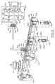
- integrally formed fuel rail assembly 102 is shown for illustrative purposes having a plurality of fuel injectors 110a-110d.
- each of the fuel injectors 110a-110d includes one of the corresponding core fuel injector assemblies 114a-114d, which are moulded within fuel rail 102, and one of the corresponding armature assemblies 136a-136d inserted within one of the corresponding sleeves 134a-134c.
- Fuel rail 102 also includes fuel inlet 106, coupled to a source of fuel such as a fuel pump (not shown), and fuel outlet 108 for returning fuel to a fuel supply or fuel tank (not shown).
- Conventional pressure regulator 112 is shown coupled to fuel rail 102 for maintaining a desired fuel pressure therein.
- fuel injectors 110a-110d are electronically actuated, via respective pair of electrical contacts 120a-120d (each pair having a positive and a negative terminal), by conventional fuel controller 60, via respective electrical connector 62.
- Fuel controller 60 is responsive to voltage signals fpa, fph, fpc, and fpd from engine controller 84 which is described in more detail in U.S. Patent No. 3,969,614 issued to Moyer and incorporated herein by reference.
- fuel injectors 110a-d meter desired quantities of fuel, at desired times, from fuel rail 102 into an intake manifold (not shown) of an internal combustion engine (not shown).
- connector board 64 is shown mounted on fuel rail 102 and includes connector tabs 66a-d, and connector tab 68.
- Conductive trace 88 is shown coupled between connector tab 68 and the positive contact of each pair of electrical contacts 120a-d.
- the negative terminal of each pair of electrical contacts 120a-d is shown coupled to respective connector tabs 66a-d via respective conductive traces 92a-d.
- conductive traces 88 and 92a-d are embedded within fuel rail 102 during the injection moulding process.
- Connector tabs 66a-d are coupled to respective connector tabs 74a-d and fuel controller 60 via connector cable 62.
- connector tab 60 is coupled to connector tab 72 on fuel controller 60 via connector cable 62.
- trimming resistors 70a-d are selected and inserted on connector board 64 in series between respective connector tabs 66a-d and 74a-d.
- Fuel controller 60 is now described with continuing reference to Figure 2.
- Connector tab 72 is shown connected to battery voltage V B for supplying V B to each positive contact of each pair of electrical contacts 120a-d.
- Conventional Darlington Pair transistors 76a-d are each shown having their collector electrodes coupled to respective connector tabs 74a-d. Each collector electrode of transistors 76a-d is also coupled to the positive plate of respective capacitors 78a-d, the negative plate being coupled to electrical ground, for providing ac filtering in a conventional manner.
- Conventional Zener diodes 80a-d are each shown having an anode coupled to electrical return and a cathode coupled to the collector of each transistor 76a-d for providing an electrical short to ground should an overload condition occur.
- the base electrode of each transistor 76a-d is shown coupled to respective actuating signals fpa-fpd from electronic engine controller 84 via respective series resistors 82a-d.
- FIG. 3A and Figure 3B A cross-sectional view of a portion of fuel rail 102 and fuel injector 110a, taken along line 3A-3A of Figure 2, is shown in Figure 3A and Figure 3B.
- core fuel injector assembly 114a is shown including coil bobbin assembly 116a inserted within a stator or magnetic core 124a.
- Coil bobbin assembly 116a includes wire 118a wound about bobbin 119a and having opposing ends connected to pair of electrical contacts 120a for connection to fuel controller 60.
- injection moulded plastic 132 seals coil bobbin assembly 116a within magnetic core 124a, and also forms both housing 144a and axial fuel passageway 126a.
- Injection moulded plastic 132 also forms fuel rail 102 and fuel path 156 within fuel rail 102 which communicates with fuel passageways 126a-126d.
- moulded plastic 132 also seals coil bobbin assembly 116a and contacts 120a from any fuel flow, such as through axial fuel passageway 126a, thereby eliminating the need for a plurality of "O" rings and additional assembly processes which were inherent in prior approaches.
- integrally forming a plastic housing around a magnetic core eliminates the need for a magnetic permeable housing which is prone to corrosion and the associated crimping, cold heading, and machining processes which were previously described disadvantages of prior approaches.
- magnetic core 124a constructed of a magnetic permeable material, includes U-shape strap 123a having its open end welded to magnetic permeable assembly 128a having axial bore 130a formed therein.
- Sleeve 134a having axially bored fuel passageway 146a and valve opening 148a circumscribed by conical seat valve 150a, is shown coupled to axial bore 130a of magnetic core 124a.
- Armature assembly 136a is shown including rotor or armature 138a, and stem 140a having conical needle 142a formed thereon for mating with conical seat valve 150a.
- Armature 138a is shown including recess 158a for positioning return spring 162a therein.
- Armature assembly 136a is shown positioned within sleeve 134a such that armature 138a resides within axial fuel passageway 126a and is biased away from upper leg 125a of magnetic core 124a by return spring 162a.
- Silicon etched nozzles 166a described in U.S. patent 4,907,748 the specification of which is incorporated herein by reference, is shown communicating with valve opening 148a of sleeve 134a and attached thereto by retaining cap 168a.
- retaining cap 168a of fuel injector 110a is adapted for insertion into the engine intake manifold (not shown) and sealed thereto by "O" ring 178.
- electronic engine controller 84 via fuel controller 60, demands a predetermined amount of fuel for delivery to the internal combustion engine by electronically actuating coil bobbin assembly 116a a predetermined time via electrical contacts 120a.
- the magnetic field coupled to magnetic core 124a via coil bobbin assembly 116a axially displaces armature 138a in an upward direction against return spring 162a thereby displacing needle 142a from conical seat valve 150a.
- Fuel then flows from fuel path 156 through axial fuel passageway 126a of core fuel injector assembly 114a, axial fuel passage 146a and valve opening 148a of sleeve 134a, and silicon etched nozzles 166a, into the intake manifold (not shown).
- coil bobbin assembly 116a When electrical power is removed from coil bobbin assembly 116a, return spring 162a downwardly deflects armature assembly 136a thereby seating needle 142a against valve opening 148a to stop fuel flow through the injector. Since coil bobbin assembly 116a and contacts 120a are hermetically sealed from the fuel passageways by injection moulded plastic 132, as previously described, fuel flowing through the passageways cannot come in contact with any electrical components. Should the bond between injection moulded plastic 132 and magnetic core 124a ever develop a slight gap, fuel would still not come in contact with any electrical components, but would simply flow around magnetic core 124a and return to the fuel passageways (126a, 127a, or 146a).
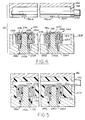
- Figures 4-6 show only two fuel injectors (110b and 110d) formed within a portion of fuel rail 102.
- the following discussion is with reference to only one fuel injector (110d), the components and process steps for fabricating being the same for fuel injectors 110a-110d.
- two piece injection mold 182 is shown having lower mold 184 and upper mold 186 in the open position.
- Lower mold 184 is shown having recess 188d with removable pin 190d inserted therein.
- Core fuel injector assembly 114d is shown positioned over pin 190d within recess 188d.
- core fuel injector assembly 114d includes coil bobbin assembly 116d, having wire 118d wound on bobbin 119d and contacts 120d ( Figures 2 ad 3B) coupled to opposing ends of wire 118d, and positioned within magnetic core 124d.
- Pin 190d is shown inserted through fuel passageway 126d of core fuel injector assembly 114d and biased against upper leg 125d of magnetic core 124d.
- Upper mold 186 is shown including injection inlet opening 196d communicating with recess 198 which has removable pin 202 disposed therein.
- Removable pin 202 includes flattened side 204 adapted for flush communication with upper leg 125d of magnetic core 124d when two piece mold 182 is assembled.
- two piece injection mold 182 is shown in the mated position with pin 202 displaced against upper leg 125d of magnetic core 124d.
- Plastic as been injected through opening 196 to form fuel rail 102 and hermetically seal coil bobbin assembly 116d and magnetic core 124d within fuel rail 102.
- removal of pin 190d and pin 202d respectively defines axial fuel passageway 126d and fuel path 198 which communicate with each other through fuel opening 122d in upper leg 125d of magnetic core 124d.
- Silicon nozzle assembly 166d is bonded to sleeve 134d in communication with valve opening 148d. Retaining cap 168d is then crimped onto sleeve 134d and "O" ring 178d positioned on sleeve 134d. Armature assembly 136d, having return spring 162d coupled to armature 138d, is inserted into sleeve 136d which is then axially inserted into fuel passageway 126d of core fuel injector assembly 114d. "O" ring 164d and retaining ring 170d are positioned for sealing sleeve 134d to housing 144d and completing the fabrication process.
- Fuel rail 102 is placed on a test stand (not shown) for measurement of fuel delivered by fuel injectors 110a-d during the voltage high state of respective fuel actuation signals fpa-fpd from electronic controller 84. More specifically, a set of trimming resistors 70a-d is first inserted on connector board 64. Referring, for example, to fuel injector 110a, coil bobbin assembly 116 is connected between V B and the output electrode of transistor 76a via series trimming resistor 70a. During the high voltage state of actuation signal fpa, transistor 76a is switched to the ON state thereby coupling electrical ground to coil bobbin assembly 116 via trimming resistor 70a.
- coil bobbin assembly is then connected in series between V B and ground through trimming resistor 70a and the dynamic impedance of transistor 76a.
- the test technician sequentially activates fuel injectors 110a-d and measures the resulting fuel flow therethrough. Trimming resistors 70a-d are then exchanged with trimming resistors of a desired resistance value to achieve substantially equivalent fuel flow through each fuel injector 110a-d.
- An advantage of the above described process for achieving uniform fuel flow by judicious selection of resistance values is that substantially equivalent fuel flow is achieved without cumbersome process steps such as the prior approach of altering the spring constant of each fuel injector as described previously.
- greater accuracy is achieved because the entire fuel rail is tunned and the need for inserting probes within the fuel flow path of an injector and the resulting inaccuracy caused thereby is eliminated.
- each fuel injector is tunned on a single fuel stand thereby eliminating inaccuracies caused by variations among different stands which is a disadvantage inherent in prior approaches.
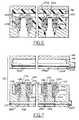
- two-piece mold 182′ is shown substantially similar to two-piece mold 182 previously described with particular reference to Figures 4-6, with the addition of longitudinal pin 220′.
- longitudinal pin 220′ is inserted as shown through pins 190a-d′.
- longitudinal pin 220′ is removed thereby defining lower fuel path 220′ which communicates with axial fuel passageways 126a-d′.
- the assembly process for fuel injectors 110a-d′ proceeds as previously described with insertion of sleeves 134a-c′ and respective armature assemblies 136a-c′.
- each fuel injectors 110a-d′ are formed within fuel rail 102′ communicating with upper fuel passageway 106′ and lower fuel passageway 122′ as shown in Figure 8.
- fuel passageway 122′ communicates with axial fuel passageways 146a-d′ via respective bores 230a-d′ through respective sleeves 134a-d′.
- Fuel is provided through upper fuel path 106′ and excess fuel returned through fuel path 122′. This configuration is shown schematically in Figure 9C.
- FIG. 9B Another alternate embodiment is provided wherein fuel is supplied through lower fuel path 122′ as shown schematically in Figure 9B.
- This particular configuration is provided by two-piece mold 182′ as follows. Pin 202′ is not utilised during the moulding process. Longitudinal pin 220′, however, is utilised to form lower fuel path 222′ as previously described. Accordingly, after the injection moulding process steps previously described, a fuel injector rail and embedded fuel injectors are formed having fuel feed only through lower fuel path 222′.
- three possible fuel feed figurations are achieved as shown schematically in Figures 9A-9C by judicious selection of pins 202′ and 220′ in two-piece mold 182′. This provides the designer and fabricators with flexibility in providing fuel rails, and also fuel injectors which was not hereto before possible.
Landscapes
- Engineering & Computer Science (AREA)
- Chemical & Material Sciences (AREA)
- Combustion & Propulsion (AREA)
- Mechanical Engineering (AREA)
- General Engineering & Computer Science (AREA)
- Manufacturing & Machinery (AREA)
- Physics & Mathematics (AREA)
- Electromagnetism (AREA)
- Fuel-Injection Apparatus (AREA)
Claims (11)
- Unité de rail d'alimentation en carburant couplée à une source de carburant, comprenant plusieurs injecteurs (110a - 110d) incluant une unité de bobine électrique (116a - 116d) et des moyens de soupape (142a - 142d, 150a - 150d) répondant mécaniquement à l'application d'une puissance électrique à ladite unité de bobine électrique (116a - 116d) afin de commander l'écoulement de carburant à travers ledit injecteur; plusieurs pignons menants électroniques (76a - 76d), chacun d'entre eux étant couplé à l'une desdites unités de bobine électrique correspondantes afin d'appliquer ladite puissance électrique, caractérisée en ce que plusieurs moyens de réglage sont fournis, chacun d'entre eux incluant une résistance séparée (70a - 70d) couplée en série entre l'un desdits pignons menants électriques (70a - 70d) et l'une desdites bobines électriques (116a - 116d), chacune desdites résistances (70a - 70d) desdits moyes de réglage présentant une valeur de résistance prédéterminée par des caractéristiques de fonctionnement de ladite unité de rail d'alimentation en carburant afin de maintenir l'écoulement de carburant essentiellement constant à travers chacun desdits injecteurs.
- Unité de rail d'alimentation en carburant selon la revendication 1, dans laquelle chacun desdits moyens de soupape inclut une armature répondant mécaniquement à ladite application de puissance électrique à ladite unité de bobine et inclut également une aiguille et un siège de soupape répondant mécaniquement à ladite armature.
- Unité de rail d'alimentation en carburant selon la revendication 1 ou 2, incluant également un rail d'alimentation en carburant couplé à chacun desdits injecteurs et dans laquelle lesdits moyens de réglage sont montés sur ledit rail d'alimentation en carburant.
- Unité de rail d'alimentation en carburant selon la revendication 1, 2 ou 3, dans laquelle chacun desdits injecteurs comprend une unité de noyau magnétique communiquant de manière magnétique avec une unité de bobine électrique ; et des moyens de moulage composés de plastique moulé par injection destinés à former un rail d'alimentation en carburant pouvant communiquer avec la source de carburant et à sceller hermétiquement chacune desdites unités de bobine et chacuns desdits noyaux magnétiques à l'intérieur dudit rail d'alimentation en carburant, l'unité de rail d'alimentation en carburant constituant de ce fait une unité formée de manière intégrale.
- Unité de rail d'alimentation en carburant selon la revendication 4, dans laquelle lesdits moyens de moulage forment également un trajet pour le carburant à l'intérieur dudit rail d'alimentation en carburant et des conduits pour le carburant à l'intérieur de chacune desdites unités d'injecteur du noyau communiquant avec ledit trajet pour le carburant.
- Unité de rail d'alimentation en carburant selon la revendication 4 ou 5, dans laquelle chacune desdites unités d'injecteur inclut un contact électrique s'étendant depuis l'unité de bobine de celui-ci; les moyens de moulage scellent hermétiquement chacune desdites unités de bobine à l'intérieur de chacun desdits noyaux magnétiques et forment également une cavité d'unité de bobine à l'intérieur de chacune desdites unités de bobine; le rail d'alimentation en durant formé par lesdits moyens de moulage communiquant avec chacune desdites cavités d'unité de bobine de manière à coupler chacune desdites cavités d'unité de bobine à une source de carburant ; et chacune desdites armatures étant insérée de manière coulissante dans l'une desdites cavités d'unité de bobine et chacune desdites unités de soupape étant couplée à l'une desdites cavités d'unité de bobine correspondante.
- Unité de rail d'alimentation en carburant selon la revendication 6, comprenant également une tuyère gravée en silicium couplée à chacun desdits moyens de soupape.
- Unité de rail d'alimentation en carburant selon la revendication 5, 6 ou7, comprenant également plusieurs bandes électroconductrices encastrées dans ledit rail d'alimentation en carburant par ledit plastique moulé par injection, chacune desdites bandes étant reliée à l'une desdites résistances.
- Méthode destinée à former de manière intégrale une unité de rail d'alimentation en carburant présentant plusieurs unités d'injecteurs du noyau, chacunes d'entre elles étant couplée à une source de carburant, caractérisée par les étapes consistant à placer chacune desdites plusieurs unités de bobine électrique à l'intérieur d'un noyau magnétique de manière à former plusieurs unités d'injecteurs à noyau et à placer chacune desdites unités d'injecteurs à noyau à l'intérieur d'un moule séparé ; à insérer chacune desdites plusieurs premières épingles amovibles dans une ouverture formée de manière concentrique dans chacune desdites unités d'injecteurs à noyau ; insérer une seconde épingle amovible dans ledit moule qui communique avec chacune desdites unités d'injecteurs à noyau; injecter du plastique dans ledit moule de manière à sceller hermétiquement chacune desdites unités de bobine à l'intérieur dudit noyau magnétique correspondant pour chacune desdites unités d'injecteurs à noyau ; retirer lesdites premières épingles de manière à définir un conduit pour le carburant dans chacune desdites unités d'injecteurs à noyau et retirer ladite seconde épingle de manière à définir un trajet pour le carburant communiquant avec chacun desdits conduits pour le carburant ; retirer ledit moule séparable de manière à munir ladite unité de rail d'alimentation en carburant de plusieurs unités d'injecteurs à noyau scellées hermétiquement dans celle-ci ; insérer chacune desdites plusieurs armatures dans chacun desdits conduits pour le carburant desdites unités d'injecteurs à noyau ; coupler chacune desdites plusieurs unités de soupape à chacun desdits conduits pour le carburant desdites unités d'injecteurs à noyau ; et relier l'une desdites plusieurs résistances en série entre l'une desdites unités de bobine et l'un desdits plusieurs pignons menants électroniques en nombre égal, lesdites résistances étant sélectionnées avec une valeur de résistance destinée à fournir un écoulement de carburant essentiellement constant à travers chacune desdites unités d'injecteurs à noyau.
- Méthode selon la revendication 9, comprenant également les étapes consistant à coupler chacune desdites plusieurs unités de tuyères à chacune desdites unités de soupape.
- Méthode selon la revendication 9, comprenant également les étapes consistant à insérer chacun desdits plusieurs ressorts entre chacune desdites armatures et un noyau magnétique correspondant.
Applications Claiming Priority (2)
| Application Number | Priority Date | Filing Date | Title |
|---|---|---|---|
| US630913 | 1990-12-20 | ||
| US07/630,913 US5086743A (en) | 1990-12-20 | 1990-12-20 | Integrally formed and tuned fuel rail/injectors |
Publications (2)
| Publication Number | Publication Date |
|---|---|
| EP0492876A1 EP0492876A1 (fr) | 1992-07-01 |
| EP0492876B1 true EP0492876B1 (fr) | 1995-01-25 |
Family
ID=24529076
Family Applications (1)
| Application Number | Title | Priority Date | Filing Date |
|---|---|---|---|
| EP91311433A Expired - Lifetime EP0492876B1 (fr) | 1990-12-20 | 1991-12-09 | Rampe d'alimentation en carburant |
Country Status (4)
| Country | Link |
|---|---|
| US (1) | US5086743A (fr) |
| EP (1) | EP0492876B1 (fr) |
| CA (1) | CA2053738A1 (fr) |
| DE (1) | DE69107042T2 (fr) |
Families Citing this family (46)
| Publication number | Priority date | Publication date | Assignee | Title |
|---|---|---|---|---|
| DE4002393A1 (de) * | 1990-01-27 | 1991-08-01 | Bosch Gmbh Robert | Kraftstoffeinspritzsystem fuer brennkraftmaschinen |
| US5178115A (en) * | 1991-02-11 | 1993-01-12 | Siemens Automotive L.P. | Fuel rail assembly having self-contained electronics |
| DE4206370A1 (de) * | 1991-05-17 | 1992-11-19 | Mann & Hummel Filter | Steuerleiste in kunststoffkompaktbauweise |
| US5178114A (en) * | 1991-08-06 | 1993-01-12 | Siemens Automotive L.P. | Fuel rail end closure and electrical connector |
| DE4131537A1 (de) * | 1991-09-21 | 1993-04-01 | Bosch Gmbh Robert | Brennstoffverteiler |
| JP2700115B2 (ja) * | 1992-02-26 | 1998-01-19 | 矢崎総業株式会社 | エンジン取付け部品の電気配線方法 |
| US5265576A (en) * | 1993-01-08 | 1993-11-30 | Stanadyne Automotive Corp. | Calibration system for electrically controlled fuel injection pump |
| US5297523A (en) * | 1993-02-26 | 1994-03-29 | Caterpillar Inc. | Tuned actuating fluid inlet manifold for a hydraulically-actuated fuel injection system |
| US5471961A (en) * | 1993-09-02 | 1995-12-05 | Siemens Automotive L.P. | Electrical circuitry of a fuel rail assembly |
| US5447140A (en) * | 1993-12-20 | 1995-09-05 | General Motors Corporation | Fuel injection |
| US5634448A (en) * | 1994-05-31 | 1997-06-03 | Caterpillar Inc. | Method and structure for controlling an apparatus, such as a fuel injector, using electronic trimming |
| US5568798A (en) * | 1995-06-08 | 1996-10-29 | Siemens Automotive Corporation | Plastic fuel rail having integrated electrical wiring |
| US5531202A (en) * | 1995-07-18 | 1996-07-02 | Siemens Automotive Corporation | Fuel rail assembly having internal electrical connectors |
| DE19546441A1 (de) * | 1995-12-13 | 1997-06-19 | Bosch Gmbh Robert | Brennstoffverteiler |
| US5575264A (en) * | 1995-12-22 | 1996-11-19 | Siemens Automotive Corporation | Using EEPROM technology in carrying performance data with a fuel injector |
| US5598824A (en) * | 1996-04-15 | 1997-02-04 | Ford Motor Company | Fuel delivery system for an internal combustion engine |
| DE19732063B4 (de) * | 1997-07-25 | 2006-03-16 | Audi Ag | Vorrichtung zum Einsetzen von Einspritzventilen |
| US6186106B1 (en) | 1997-12-29 | 2001-02-13 | Visteon Global Technologies, Inc. | Apparatus for routing electrical signals in an engine |
| US6053148A (en) * | 1998-02-21 | 2000-04-25 | Ford Motor Company | Intake manifold for an internal combustion engine |
| US6170463B1 (en) | 1999-03-05 | 2001-01-09 | Outboard Marine Corporation | Method and apparatus for optimizing engine operation |
| JP2000265922A (ja) * | 1999-03-16 | 2000-09-26 | Honda Motor Co Ltd | 燃料噴射装置 |
| US6516658B1 (en) * | 1999-04-16 | 2003-02-11 | Siemens Vdo Automotive Corporation | Identification of diesel engine injector characteristics |
| DE10007691B4 (de) * | 2000-02-19 | 2006-10-26 | Robert Bosch Gmbh | Verfahren und Vorrichtung zum Speichern und/oder Auslesen von Daten eines Kraftstoffzumesssystems |
| US6622700B2 (en) * | 2000-10-24 | 2003-09-23 | Siemens Vdo Automotive, Inc. | Integrated fuel system and wiring harness |
| JP2002202025A (ja) * | 2000-11-06 | 2002-07-19 | Auto Network Gijutsu Kenkyusho:Kk | インジェクタ一体型モジュール |
| US6769637B2 (en) * | 2000-12-04 | 2004-08-03 | Autonetworks Technologies, Ltd. | Injector module, injector electric block body, injector main bodies to be used for the same, and ignition coil device module |
| JP4217941B2 (ja) * | 2000-12-08 | 2009-02-04 | 株式会社デンソー | 燃料噴射装置及びその調整方法 |
| US6651629B2 (en) | 2001-01-04 | 2003-11-25 | Mccoy John C. | Internal energizable voltage or current source for fuel injector identification |
| US6497218B2 (en) | 2001-02-28 | 2002-12-24 | Robert Bosch Corporation | Fuel injector module |
| US6959695B2 (en) | 2001-10-17 | 2005-11-01 | Robert Bosch Corporation | Multi-point fuel injection module |
| DE10236505B4 (de) * | 2002-08-09 | 2007-09-06 | Mtu Friedrichshafen Gmbh | Brennkraftmaschine mit einem Verbindungsmittel zum Verbinden eines ersten mit einem zweiten Abschnitt eines Kabelbaums an einem Zylinderkopf-Gehäuse |
| US6981662B2 (en) * | 2002-11-08 | 2006-01-03 | Siemens Diesel Systems Technology | Coupling device assembly |
| US6801847B2 (en) | 2002-12-27 | 2004-10-05 | Caterpillar Inc | Method for estimating fuel injector performance |
| US6879903B2 (en) * | 2002-12-27 | 2005-04-12 | Caterpillar Inc | Method for estimating fuel injector performance |
| US7007674B2 (en) | 2003-04-01 | 2006-03-07 | Robert Bosch Corporation | Fuel rail assembly |
| US20050051138A1 (en) * | 2003-09-08 | 2005-03-10 | Robert Bosch Corporation | Intake manifold assembly |
| JP2006161764A (ja) * | 2004-12-10 | 2006-06-22 | Keihin Corp | 燃料分配管におけるワイヤハーネス取付け構造 |
| US7523741B2 (en) * | 2005-03-30 | 2009-04-28 | Kurz - Kasch, Inc. | Fuel rail |
| US7252071B2 (en) * | 2005-03-30 | 2007-08-07 | Delaware Capital Formation, Inc. | Fuel rail |
| DE102006013543A1 (de) * | 2006-03-24 | 2007-09-27 | Man Nutzfahrzeuge Ag | Kabelstrang zur Ansteuerung von Einspritzventilen |
| US9212642B2 (en) * | 2012-12-06 | 2015-12-15 | Msd Llc | Fuel rail-cooled engine control system |
| US10234496B2 (en) | 2016-02-16 | 2019-03-19 | Woodward, Inc. | Detection of valve open time for solenoid operated fuel injectors |
| US10401398B2 (en) | 2017-03-03 | 2019-09-03 | Woodward, Inc. | Fingerprinting of fluid injection devices |
| EP3721070B1 (fr) * | 2017-12-08 | 2025-10-08 | Volvo Truck Corporation | Dispositif pour système d'injection de carburant à rampe de distribution commune |
| EP3767142B1 (fr) * | 2019-07-19 | 2025-02-26 | Fico Transpar, S.A. | Système d'éjection de fluide pour le nettoyage de surfaces optiques dans des véhicules automobiles, avec soupape à commande électromagnétique |
| US11274642B1 (en) * | 2021-08-31 | 2022-03-15 | Denso International America, Inc. | Fuel rail assembly |
Family Cites Families (20)
| Publication number | Priority date | Publication date | Assignee | Title |
|---|---|---|---|---|
| US3045290A (en) * | 1957-10-11 | 1962-07-24 | Anderson Controls Inc | Method of encapsulating coils |
| US3796924A (en) * | 1972-12-29 | 1974-03-12 | Technical Arco Establishment | Electric control system for actuating in a predetermined sequence a plurality of electro-magnetic relays |
| US4190022A (en) * | 1975-11-06 | 1980-02-26 | Allied Chemical Corporation | Fuel injection system with correction for incidental system variables |
| US4221192A (en) * | 1978-06-26 | 1980-09-09 | Cummins Engine Company, Inc. | Fuel injector and common rail fuel supply system |
| JPS586050B2 (ja) * | 1978-07-13 | 1983-02-02 | 三菱自動車工業株式会社 | 機関用燃料供給装置 |
| DE2964900D1 (en) * | 1978-08-24 | 1983-03-31 | Lucas Ind Plc | Control circuits for solenoids |
| DE2950692A1 (de) * | 1979-12-17 | 1981-07-02 | Robert Bosch Gmbh, 7000 Stuttgart | Einrichtung zum steuern des elektrischen stromes durch einen induktiven verbraucher, insbesondere durch eine kraftstoffzumessventil bei einer brennkraftmaschine |
| DE3139987A1 (de) * | 1981-10-08 | 1983-04-28 | Robert Bosch Gmbh, 7000 Stuttgart | Steuereinrichtung fuer einen elektromagnetischen verbraucher in einem kraftfahrzeug, insbesondere ein magnetventil oder ein stellmagnet |
| US4402294A (en) * | 1982-01-28 | 1983-09-06 | General Motors Corporation | Fuel injection system having fuel injector calibration |
| DE3325044C2 (de) * | 1983-07-12 | 1986-10-23 | Robert Bosch Gmbh, 7000 Stuttgart | Stromregler für einen elektromagnetischen Verbraucher in Verbindung mit Brennkraftmaschinen |
| JPS60108561A (ja) * | 1983-11-15 | 1985-06-14 | Nippon Denso Co Ltd | 燃料分配管 |
| DE3510157A1 (de) * | 1985-03-21 | 1986-09-25 | Vdo Adolf Schindling Ag, 6000 Frankfurt | Einrichtung zur zeitgesteuerten ansteuerung elektromagnetisch betaetigbarer kraftstoffeinspritzventile |
| US4970622A (en) * | 1986-12-03 | 1990-11-13 | Buechl Josef | Method and apparatus for controlling the operation of an electromagnet |
| DE3736198A1 (de) * | 1987-10-26 | 1989-05-18 | Voest Alpine Automotive | Kraftstoffeinspritzduese fuer brennkraftmaschinen |
| US4895124A (en) * | 1987-12-02 | 1990-01-23 | Proprietary Technology, Inc. | Fuel and electrical distribution system for fuel injected engines |
| JPH0528727Y2 (fr) * | 1988-03-31 | 1993-07-23 | ||
| US4980793A (en) * | 1988-04-29 | 1990-12-25 | Chrysler Corporation | Open loop control of solenoid coil driver |
| DE3914487A1 (de) * | 1989-05-02 | 1990-11-08 | Bosch Gmbh Robert | Kraftstoffverteiler fuer kraftstoffeinspritzanlagen von brennkraftmaschinen |
| US4972293A (en) * | 1989-07-31 | 1990-11-20 | Allied-Signal Inc. | Coded electromagnetic device and system therefor |
| US4950171A (en) * | 1989-08-11 | 1990-08-21 | Itt Corporation | Fuel injector connector system |
-
1990
- 1990-12-20 US US07/630,913 patent/US5086743A/en not_active Expired - Lifetime
-
1991
- 1991-10-18 CA CA002053738A patent/CA2053738A1/fr not_active Abandoned
- 1991-12-09 EP EP91311433A patent/EP0492876B1/fr not_active Expired - Lifetime
- 1991-12-09 DE DE69107042T patent/DE69107042T2/de not_active Expired - Fee Related
Also Published As
| Publication number | Publication date |
|---|---|
| US5086743A (en) | 1992-02-11 |
| DE69107042T2 (de) | 1995-05-18 |
| EP0492876A1 (fr) | 1992-07-01 |
| CA2053738A1 (fr) | 1992-06-21 |
| DE69107042D1 (de) | 1995-03-09 |
Similar Documents
| Publication | Publication Date | Title |
|---|---|---|
| EP0492876B1 (fr) | Rampe d'alimentation en carburant | |
| US5189782A (en) | Method of making integrally formed and tuned fuel rail/injectors | |
| EP0487198B1 (fr) | Conduite de carburant et injecteurs intégrés et méthode de fabrication | |
| US5185919A (en) | Method of manufacturing a molded fuel injector | |
| US5150842A (en) | Molded fuel injector and method for producing | |
| US20010002680A1 (en) | Modular two part fuel injector | |
| JP2749839B2 (ja) | エンジンの燃料噴射装置 | |
| US5584704A (en) | Device for the common electrical contacting of a plurality of electrically excitable aggregates of internal combustion engines | |
| US6367334B2 (en) | Combination pressure sensor and regulator for direct injection engine fuel system | |
| US4907745A (en) | Fuel injection valve and method for adjusting it | |
| JP2000502770A (ja) | 燃料噴射器に性能データを備えるためのeeprom技術の使用 | |
| US6062200A (en) | Motor fuel dispenser | |
| EP0776418A1 (fr) | Induit a circulation amelioree d'un injecteur de carburant | |
| US5531202A (en) | Fuel rail assembly having internal electrical connectors | |
| JPH11502282A (ja) | 燃料噴射装置 | |
| KR20180003556A (ko) | 센서를 구비한 연료 인젝터 | |
| DE102010016230B4 (de) | Kraftstoffeinspritzgerät | |
| US20030094513A1 (en) | Fuel-injection valve and a method for regulating the same | |
| US6257509B1 (en) | Fuel injector | |
| US6565020B1 (en) | Electromagnetic actuator and stator design in a fuel injector assembly | |
| WO2011000663A1 (fr) | Injecteur de fluide, et procédé et appareil d'actionnement de celui-ci | |
| US6175168B1 (en) | Overmolded stator for fuel metering solenoid and method of manufacturing same | |
| JPS61215450A (ja) | 電磁作動可能な燃料噴射弁の時間制御たれる制御装置 | |
| DE102010016231B4 (de) | Kraftstoffeinspritzgerät | |
| US6302341B1 (en) | Injector for supplying fuel |
Legal Events
| Date | Code | Title | Description |
|---|---|---|---|
| PUAI | Public reference made under article 153(3) epc to a published international application that has entered the european phase |
Free format text: ORIGINAL CODE: 0009012 |
|
| AK | Designated contracting states |
Kind code of ref document: A1 Designated state(s): DE FR GB |
|
| 17P | Request for examination filed |
Effective date: 19921030 |
|
| 17Q | First examination report despatched |
Effective date: 19931014 |
|
| GRAA | (expected) grant |
Free format text: ORIGINAL CODE: 0009210 |
|
| AK | Designated contracting states |
Kind code of ref document: B1 Designated state(s): DE FR GB |
|
| PG25 | Lapsed in a contracting state [announced via postgrant information from national office to epo] |
Ref country code: FR Effective date: 19950125 |
|
| REF | Corresponds to: |
Ref document number: 69107042 Country of ref document: DE Date of ref document: 19950309 |
|
| EN | Fr: translation not filed | ||
| PLBE | No opposition filed within time limit |
Free format text: ORIGINAL CODE: 0009261 |
|
| STAA | Information on the status of an ep patent application or granted ep patent |
Free format text: STATUS: NO OPPOSITION FILED WITHIN TIME LIMIT |
|
| REG | Reference to a national code |
Ref country code: GB Ref legal event code: 746 Effective date: 19951107 |
|
| 26N | No opposition filed | ||
| PGFP | Annual fee paid to national office [announced via postgrant information from national office to epo] |
Ref country code: GB Payment date: 19981130 Year of fee payment: 8 |
|
| PGFP | Annual fee paid to national office [announced via postgrant information from national office to epo] |
Ref country code: DE Payment date: 19981219 Year of fee payment: 8 |
|
| PG25 | Lapsed in a contracting state [announced via postgrant information from national office to epo] |
Ref country code: GB Free format text: LAPSE BECAUSE OF NON-PAYMENT OF DUE FEES Effective date: 19991209 |
|
| GBPC | Gb: european patent ceased through non-payment of renewal fee |
Effective date: 19991209 |
|
| PG25 | Lapsed in a contracting state [announced via postgrant information from national office to epo] |
Ref country code: DE Free format text: LAPSE BECAUSE OF NON-PAYMENT OF DUE FEES Effective date: 20001003 |