EP0493206A1 - Fahrzeug mit Mischlenkung - Google Patents
Fahrzeug mit Mischlenkung Download PDFInfo
- Publication number
- EP0493206A1 EP0493206A1 EP91403451A EP91403451A EP0493206A1 EP 0493206 A1 EP0493206 A1 EP 0493206A1 EP 91403451 A EP91403451 A EP 91403451A EP 91403451 A EP91403451 A EP 91403451A EP 0493206 A1 EP0493206 A1 EP 0493206A1
- Authority
- EP
- European Patent Office
- Prior art keywords
- wheels
- vehicle
- steering
- speed
- vehicle according
- Prior art date
- Legal status (The legal status is an assumption and is not a legal conclusion. Google has not performed a legal analysis and makes no representation as to the accuracy of the status listed.)
- Granted
Links
Images


Classifications
-
- B—PERFORMING OPERATIONS; TRANSPORTING
- B62—LAND VEHICLES FOR TRAVELLING OTHERWISE THAN ON RAILS
- B62D—MOTOR VEHICLES; TRAILERS
- B62D9/00—Steering deflectable wheels not otherwise provided for
-
- B—PERFORMING OPERATIONS; TRANSPORTING
- B60—VEHICLES IN GENERAL
- B60K—ARRANGEMENT OR MOUNTING OF PROPULSION UNITS OR OF TRANSMISSIONS IN VEHICLES; ARRANGEMENT OR MOUNTING OF PLURAL DIVERSE PRIME-MOVERS IN VEHICLES; AUXILIARY DRIVES FOR VEHICLES; INSTRUMENTATION OR DASHBOARDS FOR VEHICLES; ARRANGEMENTS IN CONNECTION WITH COOLING, AIR INTAKE, GAS EXHAUST OR FUEL SUPPLY OF PROPULSION UNITS IN VEHICLES
- B60K17/00—Arrangement or mounting of transmissions in vehicles
- B60K17/34—Arrangement or mounting of transmissions in vehicles for driving both front and rear wheels, e.g. four wheel drive vehicles
- B60K17/344—Arrangement or mounting of transmissions in vehicles for driving both front and rear wheels, e.g. four wheel drive vehicles having a transfer gear
- B60K17/346—Arrangement or mounting of transmissions in vehicles for driving both front and rear wheels, e.g. four wheel drive vehicles having a transfer gear the transfer gear being a differential gear
-
- B—PERFORMING OPERATIONS; TRANSPORTING
- B62—LAND VEHICLES FOR TRAVELLING OTHERWISE THAN ON RAILS
- B62D—MOTOR VEHICLES; TRAILERS
- B62D11/00—Steering non-deflectable wheels; Steering endless tracks or the like
- B62D11/02—Steering non-deflectable wheels; Steering endless tracks or the like by differentially driving ground-engaging elements on opposite vehicle sides
- B62D11/06—Steering non-deflectable wheels; Steering endless tracks or the like by differentially driving ground-engaging elements on opposite vehicle sides by means of a single main power source
- B62D11/10—Steering non-deflectable wheels; Steering endless tracks or the like by differentially driving ground-engaging elements on opposite vehicle sides by means of a single main power source using gearings with differential power outputs on opposite sides, e.g. twin-differential or epicyclic gears
- B62D11/14—Steering non-deflectable wheels; Steering endless tracks or the like by differentially driving ground-engaging elements on opposite vehicle sides by means of a single main power source using gearings with differential power outputs on opposite sides, e.g. twin-differential or epicyclic gears differential power outputs being effected by additional power supply to one side, e.g. power originating from secondary power source
- B62D11/18—Steering non-deflectable wheels; Steering endless tracks or the like by differentially driving ground-engaging elements on opposite vehicle sides by means of a single main power source using gearings with differential power outputs on opposite sides, e.g. twin-differential or epicyclic gears differential power outputs being effected by additional power supply to one side, e.g. power originating from secondary power source the additional power supply being supplied hydraulically
-
- B—PERFORMING OPERATIONS; TRANSPORTING
- B62—LAND VEHICLES FOR TRAVELLING OTHERWISE THAN ON RAILS
- B62D—MOTOR VEHICLES; TRAILERS
- B62D7/00—Steering linkage; Stub axles or their mountings
- B62D7/06—Steering linkage; Stub axles or their mountings for individually-pivoted wheels, e.g. on king-pins
- B62D7/08—Steering linkage; Stub axles or their mountings for individually-pivoted wheels, e.g. on king-pins the pivotal axes being situated in a single plane transverse to the longitudinal centre line of the vehicle
Definitions
- the present invention relates to motor vehicles comprising at least four drive wheels and in particular vehicles whose power is distributed to the wheels per side as is the case for most vehicles of the track type.
- the invention relates more particularly to a mixed steering system adapted to these vehicles.
- Wheeled vehicles have two ways to modify their trajectory.
- the first means consists in having, depending on the number of axles, one or more steering axles, that is to say it is possible to orient, by appropriate means, the so-called steered wheels, which allows the vehicle to leave the straight path which it would keep if the wheels were fixed.
- This well-known solution is adopted for all motor vehicles, light or heavy.
- the second way is to keep the wheels in a fixed position and to vary the speed of rotation of those located on the same side of the vehicle compared to those located on the other side.
- the vehicle turns on the side of the wheels which are slowed down; if the wheels are immobilized on one side, the vehicle turns around its stopped side; if the direction of rotation of the wheels is reversed between one side and the opposite side, the vehicle turns around its axis.
- This steering process well known under the name of "skid steering" is used for tracked vehicles; it is also used on certain military wheeled vehicles.
- this configuration does not allow the machine to pivot around its center of gravity to perform a U-turn on the spot.
- the present invention relates to a wheeled vehicle which can change direction by orienting the steered wheels more or less or by keeping the wheels in line but by varying the speed of the wheels located on one side relative to the speed of the wheels located on the other side, or finally, by changing the orientation of the steered wheels and by simultaneously varying the speed of the wheels on one side relative to the other side.
- the orientation of the steered wheels can be obtained independently of the propulsion means and of those linked to the variation of the driving speed of the driving wheels of the vehicle.
- This transmission makes it possible to give, to the vehicle which is equipped with it, particularly efficient mobility characteristics since it can move at high speed on the road like a vehicle with conventional steered wheels and that, when traveling in all terrain or for parking maneuvers, it has extremely small turning radii; he can even turn around on the spot.
- the low angular travel of the steered wheels makes it possible to maintain a very large body width between wheels, which notably improves the transport capacity of the vehicle.
- the vehicle according to the invention motorized with at least four driving wheels and of the type with power distribution per side, comprising a mixed steering constituted by a first steering mode comprising means for orienting the wheels of at least one axle , and a second steering mode of the "skid steering" type, that is to say comprising means capable of establishing a different speed of the wheels per side;
- this vehicle comprises a differential mechanism and a set of means which allow the driver to involve one and / or the other of the directions, depending on at least one of factors such as the speed of said vehicle or the terrain on which it evolves.
- the vehicle comprises a differential mechanism of the superimposed type with a motorized neutral shaft, which differential mechanism is interposed between the engine member of the vehicle and the power distribution to the wheels; disengageable coupling means are arranged between said neutral shaft and its motorization to remove or activate the steering mode by "skid steering” according to the desired mobility (all terrain, maneuvers, high speed on the road ).
- the coupling means can be various: dog clutch, clutch, distributor, etc., they are mainly a function of the choice of the driving source of the neutral shaft.
- the action of activating or canceling the skid steering mode can either be left to the initiative of the driver, or be entirely automatic.
- the motorization of the neutral shaft consists of a hydraulic motor powered by a variable flow pump, which pump is driven by the engine member of the vehicle.
- the coupling means consist of a two-position electrically controlled distributor; the first position "closed circuit” activates the steering mode by "skid steering", the second position connecting the HP branch to the LP branch of the pump, associated with the zeroing of its displacement, removes the mode direction "skid steering".
- the motorization of the neutral shaft consists of a hydraulic motor powered by a variable flow pump, which pump is driven by the engine member of the vehicle.
- variable flow pump is slaved to the means for orienting the wheels so as to produce an association of the two steering modes as a function of the speed of the vehicle.
- the means for orienting the wheels consist of a conventional steering system, the movement of which is limited so as to cause relatively reduced wheel travel.
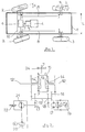
- the vehicle 1, shown in Figure 1 is equipped with an axle with 2-wheel steering, preferably arranged at the front, and an axle with 3 fixed wheels, arranged at the rear.
- the powertrain of the vehicle 1 consists of an engine member 4 of the thermal engine type, coupled to a gearbox 5.
- the gearbox 5 is mechanically linked to a differential mechanism 6 by means of the shaft 7.
- This differential mechanism is of the overlapping type. It provides a classic differential function and, in addition, a skid steering function. Power is transmitted to the front wheels 2 by the differential 6 and it is also transmitted to the rear wheels 3, by means of shafts 8 arranged on each side.
- wheels 2 and 3 can be equipped with a planetary reduction gear 9 incorporated in the hub.
- the front wheels 2 are connected together by a steering bar 10 controlled by a conventional steering system with steering wheel or the like.
- the angular movement of the wheels 2 is limited.
- This angular movement d can be limited to half of what is usually allowed (of the order of 15 to 20 °), relative to the longitudinal axis of the vehicle.
- This low angular clearance makes it possible to maintain a large body width L , at the level of the steering axle, which appreciably improves the transport capacity of the vehicle.
- Such a differential mechanism is similar to the mechanism described in the document FR 2.425.365 in FIG. 5. It is also described in detail in the document FR 2.627.832.
- the mechanism shown in Figure 2 includes, as in the document cited above, a device for controlling the speed difference between the half-shafts 12, 12 ′.
- This mechanism essentially consists of a hydraulic pump 17 connected to the neutral shaft 15 by means of a pair of pinions 18. This hydraulic pump 17 controls the sliding of the differential by means of a nozzle 19 with variable section.
- the differential mechanism also comprises means which constitute a skid steering control.
- These means essentially consist of a hydraulic pump 20 driven by the motor member 4 for example.
- This hydraulic pump 20 supplies, in both directions of rotation, a hydraulic motor 21 which is bypassed by a distributor 22.
- This distributor 22 consists of a distributor with two positions electrically controlled; the first position “closed circuit allows to activate the steering mode by" skid steering ", the second position connecting the HP branch to the BP branch of the pump, associated with the zeroing of its displacement, removes the steering mode
- This "skid steering” motor 21 is coupled to the neutral shaft 15 by means of a pair of pinions 23.
- the vehicle can be steered by means of the steered wheels only 2.
- the distributor 22 short-circuits the motor 21, the hydrostatic transmission is inactive.
- the movement of the gearbox 5 is transmitted to the right and left wheels of the vehicle by the half-shafts 12, 12 ′.
- the vehicle behaves like a vehicle with conventional wheels, fitted with an inter-side differential.
- This differential thanks to the slip control device, and in particular to the hydraulic pump 17 connected to the neutral shaft 15, makes it possible to control the torques on the wheels, by side.
- the steering wheels can be used over the entire speed range of the vehicle, both low speeds and high speeds.
- the distributor 22 When the vehicle is steered in “skid steering” mode, in certain configurations of use, such as in all terrain, the distributor 22 is positioned to close the hydraulic circuit of the engine 21.
- the action on the vehicle steering wheel can act to vary the displacement of the hydraulic pump 20. Depending on the orientation of the displacement variation lever of this pump 20, relative to the neutral point, it can be delivered by an outlet or by the 'other, which allows to rotate the hydraulic motor 21 in one direction or the other.
- the rotation of the hydraulic motor 21, transmitted to the neutral shaft 15 makes it possible, by virtue of the intermediate pinion 16, to motorize the sun pinions 14, 14 ′ with opposite directions of rotation.
- the speed of rotation will be added to one of the output half-shafts and subtracted, by the same value, from the opposite output shaft.
- the difference in rotational speed between the wheels on one side of the vehicle and that of the wheels located on the other side causes a change in the trajectory of the vehicle towards the side where the wheels turn the slowest.
- FIG. 2 shows a brake 24 acting on the shaft 7 disposed at the outlet of the gearbox 5.
- this gearbox 5 is in neutral and the brake 24 is applied, the vehicle is stationary .
- the motorization of the neutral shaft 15 makes it possible to drive the half-shafts 12, 12 ′, in the opposite direction, so as to obtain a pivoting of the vehicle on its central vertical axis.
- the use of the "skid steering” mode can be subject to a speed range of the vehicle going from zero speed to 60 km / hour for example. Beyond this speed, this steering mode is uncoupled by the opening of the distributor 22; the vehicle is then steered by means of the steering mode by orientation of the wheels 2.
- the vehicle can also be steered at low speed using a combination of the two steering modes. It is indeed possible to add to the orientation of the steering wheels 2, a variation in speed of the interior wheels relative to the exterior wheels, so as to reduce the turning radius of the vehicle.
- FIG. 3 shows a vehicle according to a second embodiment.
- the differential mechanism 6 is arranged longitudinally on the vehicle and it retains the same functions.
- the power transmission to the wheels takes place, as shown in FIG. 1, by side, but by means of a transmission system grouped together on the central line of the vehicle.
- the half-shafts 12, 12 ′ of the differential mechanism 6 transmit the power to the right and left sides of the vehicle, respectively, by means of bevel gear 25 arranged in the front 26 and rear 27 axles.
- the half-shaft 12 which, in the figure, transmits power to the rear wheel 3, on the right side, also transmits the power to the front wheel 2 on the right side, by means of an intermediate shaft 28 and a pair of pinions inverters 29.
- the half-shaft 12 ′ which transmits power to the left front wheel 2, also transmits this power to the left rear wheel 3, by means of an intermediate shaft 28 ′ and a couple of reverse gears 29 ′.
- the angular references 25, for each wheel, are grouped in the front 26 and rear 27 axles, back to back.
- Figure 4 a vehicle according to the second embodiment but equipped with a set of means which allows an all-wheel drive configuration (all terrain) or a configuration with a limited number of drive wheels (road travel).
- the power transmission to the wheels takes place, as shown in FIG. 1 or 3, per side, but by means, for certain wheels, of a coupling and uncoupling device allowing operation either of the integral type or of the traction type. .
- This device could be any controlled differential or not existing, but according to a preferred embodiment, this device consists of a multi-plate clutch 30, 30 ′, and a viscocoupler 31, 31 ′ connected in series.
- this device could advantageously be inserted between a group of two wheels per side.
- the clutches 30 and 30 ′ switch automatically to obtain an all-wheel drive transmission. Similarly, when selecting the "steered wheels" mode, the clutches 30 and 30 ′ open, the disconnected wheels and shafts then turn mad as long as the grip is sufficient. On the other hand, as soon as the adhesion is insufficient, if the driving wheels slip, the viscocoupler applies a resistant torque to the driving wheels while it applies a driving torque (equal and opposite) to the free wheels. Everything therefore happens as if the viscocoupler transfers part of the engine coupler from the drive wheels to the freewheels.
- FIG. 5 shows a vehicle according to the second embodiment but equipped with a coupling and uncoupling device allowing operation either of the traction type, or of the propulsion type, or of the integral type.
- this coupling and uncoupling device consists of two multidisk clutches 32, 32 ′ and 33, 33 ′ respectively placed on the rear and front outputs of the differential mechanism 6.
- this device is simple. It suffices to act on the clutch 32, 32 ′ to transmit the power to the rear wheels only (propulsion), while a single action on the clutch 33, 33 ′ only transmits the power to the front wheels (traction).
- the two clutches are automatically switched to obtain an integral type transmission.
Landscapes
- Engineering & Computer Science (AREA)
- Chemical & Material Sciences (AREA)
- Combustion & Propulsion (AREA)
- Transportation (AREA)
- Mechanical Engineering (AREA)
- Arrangement And Driving Of Transmission Devices (AREA)
- Retarders (AREA)
Applications Claiming Priority (2)
| Application Number | Priority Date | Filing Date | Title |
|---|---|---|---|
| FR9016408 | 1990-12-28 | ||
| FR9016408A FR2671043B1 (fr) | 1990-12-28 | 1990-12-28 | Vehicule a direction mixte. |
Publications (2)
| Publication Number | Publication Date |
|---|---|
| EP0493206A1 true EP0493206A1 (de) | 1992-07-01 |
| EP0493206B1 EP0493206B1 (de) | 1994-09-07 |
Family
ID=9403780
Family Applications (1)
| Application Number | Title | Priority Date | Filing Date |
|---|---|---|---|
| EP19910403451 Expired - Lifetime EP0493206B1 (de) | 1990-12-28 | 1991-12-19 | Fahrzeug mit Mischlenkung |
Country Status (4)
| Country | Link |
|---|---|
| EP (1) | EP0493206B1 (de) |
| DE (1) | DE69103873T2 (de) |
| ES (1) | ES2063473T3 (de) |
| FR (1) | FR2671043B1 (de) |
Cited By (11)
| Publication number | Priority date | Publication date | Assignee | Title |
|---|---|---|---|---|
| EP0627335A1 (de) * | 1993-05-24 | 1994-12-07 | ETAT FRANCAIS Représenté par le Délégué Général pour l'Armement | Fahrzeug mit hydrostatischem Getriebe und Lenkung durch lenkbare Räder und Rutschlenkung |
| US6425453B1 (en) | 2000-12-08 | 2002-07-30 | Clark Equipment Company | Transmission on all wheel steer power machine |
| EP1514039A4 (de) * | 2002-05-20 | 2006-06-07 | Folsom Technologies Inc | Hydraulisches differentialgetriebe zur umlenkung von drehmomenten |
| EP1918176A1 (de) | 2006-10-25 | 2008-05-07 | J.C. Bamford Excavators Limited | Achsenanordnung und Fahrzeug |
| ITMI20081468A1 (it) * | 2008-08-05 | 2010-02-06 | Antonio Puddu | Sistema di trasmissione per veicolo a quattro ruote motrici |
| WO2011138548A2 (fr) | 2010-05-05 | 2011-11-10 | Le Moteur Moderne | Systeme de transmission a differentiel de type a arbre neutre comportant un dispositif de freinage regeneratif |
| US8414447B2 (en) | 2011-01-27 | 2013-04-09 | Zf Friedrichshafen Ag | Transmission of a power train for distribution of the drive torque between two output shafts |
| CN107933688A (zh) * | 2017-12-08 | 2018-04-20 | 徐工集团工程机械有限公司 | 一种狭小地域抢险救援消防车 |
| EP3348454A1 (de) * | 2017-01-17 | 2018-07-18 | ZF Friedrichshafen AG | Getriebe für ein rad- und/oder kettenfahrzeug |
| EP4219982A1 (de) * | 2022-01-27 | 2023-08-02 | Polestar Performance AB | Regelbares geschwindigkeitsdifferential |
| CN119022045A (zh) * | 2024-08-19 | 2024-11-26 | 滁州悦达实业有限公司 | 一种转向系统及农用变速箱 |
Families Citing this family (3)
| Publication number | Priority date | Publication date | Assignee | Title |
|---|---|---|---|---|
| FR2706847B1 (de) * | 1993-06-23 | 1995-10-27 | Giat Ind Sa | |
| FR2722464B1 (fr) * | 1994-07-18 | 1996-09-20 | Giat Ind Sa | Systeme de freinage unilateral pour vehicule motorise a roues |
| FR2872771B1 (fr) | 2004-07-07 | 2006-11-10 | Giat Ind Sa | Methode de direction mixte pour vehicule a propulsion electrique |
Citations (7)
| Publication number | Priority date | Publication date | Assignee | Title |
|---|---|---|---|---|
| US1815839A (en) * | 1927-10-01 | 1931-07-21 | Marion Steam Shovel Co | Propelling mechanism for traction operated machines |
| GB1225006A (en) * | 1965-12-22 | 1971-03-17 | Voith Getriebe Kg | A transmission for a track-laying vehicle |
| DE2403123A1 (de) * | 1973-01-24 | 1974-07-25 | Clark Equipment Co | Lenkvorrichtung |
| DE1956243B2 (de) * | 1969-11-08 | 1976-04-29 | Voith Getriebe Kg, 7920 Heidenheim | Einrichtung zur beeinflussung der lastverteilung auf die einzelnen raeder eines strassen- und gelaendefahrzeuges |
| US4420991A (en) * | 1980-03-28 | 1983-12-20 | Zahnradfabrik Friedrichshafen, Ag | Drive system for track-laying vehicle |
| EP0248582A2 (de) * | 1986-05-26 | 1987-12-09 | Toyota Jidosha Kabushiki Kaisha | Differentialgetriebe |
| FR2627832A1 (fr) * | 1988-02-26 | 1989-09-01 | Moteur Moderne Le | Systeme a trains epicycloidaux a controle d'ecart de vitesse entre des arbres d'utilisation |
Family Cites Families (1)
| Publication number | Priority date | Publication date | Assignee | Title |
|---|---|---|---|---|
| JPS5871277A (ja) * | 1981-10-22 | 1983-04-27 | Komatsu Zoki Kk | 走行車両 |
-
1990
- 1990-12-28 FR FR9016408A patent/FR2671043B1/fr not_active Expired - Fee Related
-
1991
- 1991-12-19 ES ES91403451T patent/ES2063473T3/es not_active Expired - Lifetime
- 1991-12-19 DE DE1991603873 patent/DE69103873T2/de not_active Expired - Fee Related
- 1991-12-19 EP EP19910403451 patent/EP0493206B1/de not_active Expired - Lifetime
Patent Citations (7)
| Publication number | Priority date | Publication date | Assignee | Title |
|---|---|---|---|---|
| US1815839A (en) * | 1927-10-01 | 1931-07-21 | Marion Steam Shovel Co | Propelling mechanism for traction operated machines |
| GB1225006A (en) * | 1965-12-22 | 1971-03-17 | Voith Getriebe Kg | A transmission for a track-laying vehicle |
| DE1956243B2 (de) * | 1969-11-08 | 1976-04-29 | Voith Getriebe Kg, 7920 Heidenheim | Einrichtung zur beeinflussung der lastverteilung auf die einzelnen raeder eines strassen- und gelaendefahrzeuges |
| DE2403123A1 (de) * | 1973-01-24 | 1974-07-25 | Clark Equipment Co | Lenkvorrichtung |
| US4420991A (en) * | 1980-03-28 | 1983-12-20 | Zahnradfabrik Friedrichshafen, Ag | Drive system for track-laying vehicle |
| EP0248582A2 (de) * | 1986-05-26 | 1987-12-09 | Toyota Jidosha Kabushiki Kaisha | Differentialgetriebe |
| FR2627832A1 (fr) * | 1988-02-26 | 1989-09-01 | Moteur Moderne Le | Systeme a trains epicycloidaux a controle d'ecart de vitesse entre des arbres d'utilisation |
Non-Patent Citations (1)
| Title |
|---|
| PATENT ABSTRACTS OF JAPAN vol. 7, no. 165 (M-230)(1310), 20 juillet 1983; & JP - A - 58071277 (KOMATSU ZOUKI) 27.04.1983 * |
Cited By (15)
| Publication number | Priority date | Publication date | Assignee | Title |
|---|---|---|---|---|
| EP0627335A1 (de) * | 1993-05-24 | 1994-12-07 | ETAT FRANCAIS Représenté par le Délégué Général pour l'Armement | Fahrzeug mit hydrostatischem Getriebe und Lenkung durch lenkbare Räder und Rutschlenkung |
| US6425453B1 (en) | 2000-12-08 | 2002-07-30 | Clark Equipment Company | Transmission on all wheel steer power machine |
| US6513614B2 (en) | 2000-12-08 | 2003-02-04 | Clark Equipment Company | Transmission on all wheel steer power machine |
| EP1514039A4 (de) * | 2002-05-20 | 2006-06-07 | Folsom Technologies Inc | Hydraulisches differentialgetriebe zur umlenkung von drehmomenten |
| US7832521B2 (en) | 2006-10-25 | 2010-11-16 | J.C. Bamford Excavators Limited | Axle assembly and vehicle |
| EP1918176A1 (de) | 2006-10-25 | 2008-05-07 | J.C. Bamford Excavators Limited | Achsenanordnung und Fahrzeug |
| ITMI20081468A1 (it) * | 2008-08-05 | 2010-02-06 | Antonio Puddu | Sistema di trasmissione per veicolo a quattro ruote motrici |
| WO2011138548A2 (fr) | 2010-05-05 | 2011-11-10 | Le Moteur Moderne | Systeme de transmission a differentiel de type a arbre neutre comportant un dispositif de freinage regeneratif |
| FR2959713A1 (fr) * | 2010-05-05 | 2011-11-11 | Moteur Moderne Le | Systeme de transmission a differentiel de type a arbre neutre comportant un dispositif de freinage regeneratif |
| WO2011138548A3 (fr) * | 2010-05-05 | 2012-08-30 | Le Moteur Moderne | Systeme de transmission a differentiel de type a arbre neutre comportant un dispositif de freinage regeneratif |
| US8414447B2 (en) | 2011-01-27 | 2013-04-09 | Zf Friedrichshafen Ag | Transmission of a power train for distribution of the drive torque between two output shafts |
| EP3348454A1 (de) * | 2017-01-17 | 2018-07-18 | ZF Friedrichshafen AG | Getriebe für ein rad- und/oder kettenfahrzeug |
| CN107933688A (zh) * | 2017-12-08 | 2018-04-20 | 徐工集团工程机械有限公司 | 一种狭小地域抢险救援消防车 |
| EP4219982A1 (de) * | 2022-01-27 | 2023-08-02 | Polestar Performance AB | Regelbares geschwindigkeitsdifferential |
| CN119022045A (zh) * | 2024-08-19 | 2024-11-26 | 滁州悦达实业有限公司 | 一种转向系统及农用变速箱 |
Also Published As
| Publication number | Publication date |
|---|---|
| EP0493206B1 (de) | 1994-09-07 |
| ES2063473T3 (es) | 1995-01-01 |
| FR2671043B1 (fr) | 1995-07-21 |
| FR2671043A1 (fr) | 1992-07-03 |
| DE69103873D1 (de) | 1994-10-13 |
| DE69103873T2 (de) | 1995-01-26 |
Similar Documents
| Publication | Publication Date | Title |
|---|---|---|
| EP0493206B1 (de) | Fahrzeug mit Mischlenkung | |
| EP0445841B1 (de) | Motorrad mit Vorderradantrieb und Lenkung mit Drehstab | |
| US6554085B2 (en) | Multi-wheel vehicle with transmission for driving-steering | |
| JP2004523404A (ja) | ビークル用ステアドライブ | |
| EP0158649A1 (de) | Raupenlastfahrzeug. | |
| CA3044080A1 (fr) | Train de roulement pour vehicule chenille, vehicule chenille incorporant un tel train de roulement et procede de conversion d'un vehicule a roues en vehicule chenille | |
| FR2604663A1 (fr) | Vehicule a quatre roues motrices | |
| EP0013190B2 (de) | Hydraulische Antriebsgruppe für ein Fahrzeug mit mechanischer Leistungsverzweigung beim Lenken | |
| EP1366970A2 (de) | Hydrostatische Antriebsvorrichtung für Gelenktransportwagen | |
| FR2460799A1 (fr) | Dispositif de commande de vehicules automobiles, en particulier de vehicules tout terrain | |
| CH650743A5 (fr) | Bateau mu par l'energie disponible sur un vehicule terrestre. | |
| FR2808575A1 (fr) | Differentiel pour vehicule automobile | |
| WO1981003150A1 (fr) | Vehicule tout terrain | |
| EP4410650B1 (de) | Pedalfahrzeug für kollektiven und kollaborativen transport | |
| FR2864191A1 (fr) | Differentiel asymetrique dissipatif a double embrayage excentre, pour vehicule automobile | |
| FR2509236A1 (fr) | Dispositif de transmission pour un vehicule a plusieurs essieux moteurs | |
| EP0633181B1 (de) | Kraftfahrzeuglenkung durch Herbeiführen eines Geschwindigkeitsunterschiedes zwischen rechts- und linksseitigen Rädern | |
| EP2848497B1 (de) | Schwenkmechanismus für Militärfahrzeug | |
| CA2369543A1 (fr) | Vehicule a pendularite variable guidee | |
| EP0135421B1 (de) | Kompaktes Antriebsaggregat für Fahrzeug mit zwei Triebachsen | |
| EP1352808B1 (de) | Fahrzeug mit mindestens einem Zugmittel und mindestens einem Anhänger | |
| FR2833522A1 (fr) | Vehicule motorise a trois roues | |
| FR2643317A1 (fr) | Vehicule a chassis extensible longitudinalement | |
| FR2622862A1 (fr) | Vehicule articule | |
| JP3008239U (ja) | 運搬作業車 |
Legal Events
| Date | Code | Title | Description |
|---|---|---|---|
| PUAI | Public reference made under article 153(3) epc to a published international application that has entered the european phase |
Free format text: ORIGINAL CODE: 0009012 |
|
| 17P | Request for examination filed |
Effective date: 19920103 |
|
| AK | Designated contracting states |
Kind code of ref document: A1 Designated state(s): DE ES FR GB IT SE |
|
| 17Q | First examination report despatched |
Effective date: 19930827 |
|
| GRAA | (expected) grant |
Free format text: ORIGINAL CODE: 0009210 |
|
| AK | Designated contracting states |
Kind code of ref document: B1 Designated state(s): DE ES FR GB IT SE |
|
| ITF | It: translation for a ep patent filed | ||
| GBT | Gb: translation of ep patent filed (gb section 77(6)(a)/1977) |
Effective date: 19940913 |
|
| REF | Corresponds to: |
Ref document number: 69103873 Country of ref document: DE Date of ref document: 19941013 |
|
| REG | Reference to a national code |
Ref country code: ES Ref legal event code: FG2A Ref document number: 2063473 Country of ref document: ES Kind code of ref document: T3 |
|
| EAL | Se: european patent in force in sweden |
Ref document number: 91403451.7 |
|
| PLBE | No opposition filed within time limit |
Free format text: ORIGINAL CODE: 0009261 |
|
| STAA | Information on the status of an ep patent application or granted ep patent |
Free format text: STATUS: NO OPPOSITION FILED WITHIN TIME LIMIT |
|
| 26N | No opposition filed | ||
| REG | Reference to a national code |
Ref country code: GB Ref legal event code: IF02 |
|
| PGFP | Annual fee paid to national office [announced via postgrant information from national office to epo] |
Ref country code: ES Payment date: 20051201 Year of fee payment: 15 |
|
| PGFP | Annual fee paid to national office [announced via postgrant information from national office to epo] |
Ref country code: SE Payment date: 20051206 Year of fee payment: 15 |
|
| PGFP | Annual fee paid to national office [announced via postgrant information from national office to epo] |
Ref country code: GB Payment date: 20051208 Year of fee payment: 15 Ref country code: FR Payment date: 20051208 Year of fee payment: 15 |
|
| PGFP | Annual fee paid to national office [announced via postgrant information from national office to epo] |
Ref country code: DE Payment date: 20060223 Year of fee payment: 15 |
|
| PG25 | Lapsed in a contracting state [announced via postgrant information from national office to epo] |
Ref country code: SE Free format text: LAPSE BECAUSE OF NON-PAYMENT OF DUE FEES Effective date: 20061220 |
|
| PGFP | Annual fee paid to national office [announced via postgrant information from national office to epo] |
Ref country code: IT Payment date: 20061231 Year of fee payment: 16 |
|
| PG25 | Lapsed in a contracting state [announced via postgrant information from national office to epo] |
Ref country code: DE Free format text: LAPSE BECAUSE OF NON-PAYMENT OF DUE FEES Effective date: 20070703 |
|
| EUG | Se: european patent has lapsed | ||
| GBPC | Gb: european patent ceased through non-payment of renewal fee |
Effective date: 20061219 |
|
| REG | Reference to a national code |
Ref country code: FR Ref legal event code: ST Effective date: 20070831 |
|
| PG25 | Lapsed in a contracting state [announced via postgrant information from national office to epo] |
Ref country code: GB Free format text: LAPSE BECAUSE OF NON-PAYMENT OF DUE FEES Effective date: 20061219 |
|
| REG | Reference to a national code |
Ref country code: ES Ref legal event code: FD2A Effective date: 20061220 |
|
| PG25 | Lapsed in a contracting state [announced via postgrant information from national office to epo] |
Ref country code: FR Free format text: LAPSE BECAUSE OF NON-PAYMENT OF DUE FEES Effective date: 20070102 Ref country code: ES Free format text: LAPSE BECAUSE OF NON-PAYMENT OF DUE FEES Effective date: 20061220 |
|
| PG25 | Lapsed in a contracting state [announced via postgrant information from national office to epo] |
Ref country code: IT Free format text: LAPSE BECAUSE OF NON-PAYMENT OF DUE FEES Effective date: 20071219 |