EP0493208B1 - Kühlfinger für Halbleiterschaltung und kryogenische Anordnung mit solchem Finger - Google Patents
Kühlfinger für Halbleiterschaltung und kryogenische Anordnung mit solchem Finger Download PDFInfo
- Publication number
- EP0493208B1 EP0493208B1 EP91403455A EP91403455A EP0493208B1 EP 0493208 B1 EP0493208 B1 EP 0493208B1 EP 91403455 A EP91403455 A EP 91403455A EP 91403455 A EP91403455 A EP 91403455A EP 0493208 B1 EP0493208 B1 EP 0493208B1
- Authority
- EP
- European Patent Office
- Prior art keywords
- finger
- exchanger
- outer face
- gas
- base
- Prior art date
- Legal status (The legal status is an assumption and is not a legal conclusion. Google has not performed a legal analysis and makes no representation as to the accuracy of the status listed.)
- Expired - Lifetime
Links
Images
Classifications
-
- F—MECHANICAL ENGINEERING; LIGHTING; HEATING; WEAPONS; BLASTING
- F25—REFRIGERATION OR COOLING; COMBINED HEATING AND REFRIGERATION SYSTEMS; HEAT PUMP SYSTEMS; MANUFACTURE OR STORAGE OF ICE; LIQUEFACTION SOLIDIFICATION OF GASES
- F25D—REFRIGERATORS; COLD ROOMS; ICE-BOXES; COOLING OR FREEZING APPARATUS NOT OTHERWISE PROVIDED FOR
- F25D19/00—Arrangement or mounting of refrigeration units with respect to devices or objects to be refrigerated, e.g. infrared detectors
- F25D19/006—Thermal coupling structure or interface
-
- F—MECHANICAL ENGINEERING; LIGHTING; HEATING; WEAPONS; BLASTING
- F25—REFRIGERATION OR COOLING; COMBINED HEATING AND REFRIGERATION SYSTEMS; HEAT PUMP SYSTEMS; MANUFACTURE OR STORAGE OF ICE; LIQUEFACTION SOLIDIFICATION OF GASES
- F25B—REFRIGERATION MACHINES, PLANTS OR SYSTEMS; COMBINED HEATING AND REFRIGERATION SYSTEMS; HEAT PUMP SYSTEMS
- F25B9/00—Compression machines, plants or systems, in which the refrigerant is air or other gas of low boiling point
- F25B9/02—Compression machines, plants or systems, in which the refrigerant is air or other gas of low boiling point using Joule-Thompson effect; using vortex effect
-
- H—ELECTRICITY
- H10—SEMICONDUCTOR DEVICES; ELECTRIC SOLID-STATE DEVICES NOT OTHERWISE PROVIDED FOR
- H10W—GENERIC PACKAGES, INTERCONNECTIONS, CONNECTORS OR OTHER CONSTRUCTIONAL DETAILS OF DEVICES COVERED BY CLASS H10
- H10W40/00—Arrangements for thermal protection or thermal control
- H10W40/30—Arrangements for thermal protection or thermal control wherein the packaged device is completely immersed in a fluid other than air, e.g. immersed in a cryogenic fluid
- H10W40/305—Arrangements for thermal protection or thermal control wherein the packaged device is completely immersed in a fluid other than air, e.g. immersed in a cryogenic fluid the fluid being a liquefied gas, e.g. liquid nitrogen
Definitions
- the present invention firstly relates to a hollow finger for cooling a semiconductor circuit, the wall of which delimits an interior volume intended to receive a cryogenic fluid introduced by the base of the finger, and whose free end has an outer face in thermal contact with the circuit to be cooled.
- Such a finger is used in particular in cryostats intended to maintain a semiconductor radiation detector circuit at an optimal operating temperature, of relatively low value.
- cryostat is used for infrared detectors which are used for night vision or for guiding missiles.
- the finger is of cylindrical shape, at least in the part close to its free end, and it is placed in an enclosure transparent to the radiation to be detected, at least in the area next to the detector.
- a vacuum is created inside the enclosure, to thermally isolate the finger and the outside environment.
- the detector generally comprising a mosaic of elementary detectors, converts the radiation it receives into electrical signals brought outside the enclosure by connections passing through its wall in a hermetic manner, for their exploitation.
- the cryogenic fluid which is used to cool the interior volume of the finger can be a liquefied gas like liquid nitrogen simply poured into the cold finger.
- this cooling mode is limited to the laboratory, and for civil operational systems or military, we prefer to use a fluid produced by a cryogenic machine.
- Two types of such machines are known, on the one hand Joule-Thomson expansion coolers, on the other hand closed cycle mechanical coolers.
- Joule-Thomson expansion coolers use the expansion of a compressed gas, generally nitrogen, to liquefy it.
- the compressed gas first circulates in an exchanger terminated by a diffuser at the outlet from which it expands. After expansion, the gas returns to the exchanger, outside this time, which produces a precooling of the compressed gas which is inside. After a transient period, a jet of liquid gas is obtained at the outlet of the diffuser, which bathes the interior area of the wall of the finger opposite the exterior face in thermal contact with the detector.
- the gas is supplied in principle using cylinders and valves, but the expanded gas can possibly be recovered and recompressed.
- mechanical closed-cycle coolers also use a gas, generally helium, compressed and expanded in the cold zone. They absorb heat at the cold temperature and reject it at the hot temperature in return for the expenditure of a certain energy supplied by a compressor. The operation is carried out according to a determined thermodynamic cycle.
- the known cold fingers whether the cryogenic fluid which they use comes from a Joule-Thomson expansion cooler or from a mechanical closed cycle cooler, have the drawbacks of relatively slow cooling at the start of operation, Random variations in the temperature of the detector in steady state, causing electrical noise which reduces the sensitivity of the detector, and relatively high fluid consumption in steady state.
- the present invention aims to overcome these drawbacks.
- a cooling finger of the type defined above characterized in that it comprises a first part, adjacent to said outer face, the cross section of which decreases away from said outer face .
- the part with variable section is a truncated cone and therefore appears as a funnel when the finger is vertical and its free end is towards the top.
- the cooling of the detector is faster than in known devices.
- the shape of the finger in the vicinity of its free end acts in the manner of a nozzle to ensure better circulation of the liquid and of the expanded gas, which enables faster uniform distribution of the temperature of the wall to be obtained.
- the cylindrical shape of the free end of the finger is the cause of turbulence which causes large variations in pressure and therefore random variations in temperature of the detector, at the start of operation as well as in steady state.
- the particular shape of the finger which makes it possible to reduce the turbulence of the cryogenic fluid, therefore results in a lower and more stable detector temperature in time and in space.
- the part of the finger closest to its base is of reduced transverse dimensions.
- the diameter of the part of the finger closest to its base is thus substantially smaller than the diameter of the face in thermal contact with the detector, whereas in known systems, the diameter of the entire finger is equal to the diameter of the face in thermal contact with the detector, face whose diameter is in principle equal to that of the detector.
- the organs of the cooler are housed, which determine its consumption of fluid, and therefore of energy. The smaller these organs are, the more the fluid consumption is reduced.
- the cryogenic fluid is produced by a Joule-Thomson expansion cooler, provided with an exchanger housed in a second part of the finger close to its base, and the cross section of the second part, as well as the cross section of the exchanger gradually increase as it approaches the base of the finger.
- cryogenic fluid is produced by a closed cycle cooler provided with the exchanger arranged in said volume and there is provided a layer of thermal conductive gas between said outer face and said exchanger.
- said wall is provided with grooves, in its part which corresponds to said outer face, to increase the heat exchange surface with said layer of thermal conductive gas.
- the gas of said layer is helium, the thermal conductivity of which is particularly high.
- said circuit comprises an infrared radiation detector, and a cold diaphragm is provided which is an integral part of said first part.
- Such a cold diaphragm makes it possible to limit the flux of photons generated by the ambient background seen by the detector.
- the integration of the diaphragm in the flared part makes it possible to simplify the manufacture and to eliminate welds or bondings detrimental to the reliability of the assembly.
- the present invention also relates to a cryogenic device characterized in that it comprises a cooling finger of the type defined above.
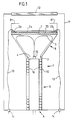
- a cryogenic device here a cryostat, comprises a hermetic enclosure 11 inside which is placed a hollow cooling finger 1, for cooling semiconductor circuits 2 a and 2 b , in thermal contact with an outer face 7 of the finger 1, which constitutes its free end.
- the thermal contact between the outer face 7 and the circuits 2 a and 2 b is provided here by a plate 70.
- Circuit 2 a is a mosaic of elementary infrared detectors intended to receive infrared radiation which pass through a window 12 of the enclosure 11, arranged opposite circuit 2 a .
- the electrical signals at the output of each of the elementary infrared detectors of circuit 2 a are processed in circuits 2 b in particular with a view to reducing the number of connections 13 which bring useful information out of the enclosure for their use. It is important to reduce the number of connections 13 because each of them must be provided with a sealed bushing 14 and poses problems of space.
- each connection 13 is the source of heat losses liable to make it more difficult to cool the free end of the finger 1.
- the finger 1 is formed by a wall 3 which delimits an interior volume 4 which receives a cryogenic fluid at the outlet of the diffuser 15 of a Joule-Thomson expansion cooler.
- the body of finger 1 here has two parts.
- a first part 8, adjacent to the face 7, has the shape of a truncated cone whose cross section gradually decreases away from the face 7.
- a second part 9, cylindrical, extends from the base 6 of the finger to the end, of smallest cross-section, of the conical part 8.
- the Joule-Thomson expansion cooler is provided with an exchanger 10 comprising a conduit wound in a spiral against the wall 3 of the part 9 of the finger 1.
- a cold diaphragm 81 forms an integral part of the conical part 8, that is to say that it is produced at the same time and in the same material as the finger 1.
- This material is for example stainless steel or material known as Kovar.
- the diaphragm 81 has the shape of a crown which masks the periphery of the detector 2 a , and which is connected to the widest end of the conical part 8 via a cylindrical portion.
- the device which has just been described operates as follows.
- the cryogenic fluid here compressed nitrogen delivered by a bottle not shown, is introduced through the base 6 of the finger into the exchanger 10.
- the gas reaches the diffuser 15 disposed in the part the narrowest of the conical part 8, and it relaxes in the interior volume of this conical part.
- the expanded gas is then channeled between the wall 3 and a wall 16 to circulate around the duct of the exchanger 10, to cool the compressed gas which circulates therein.
- the diffuser 15 delivers a jet of liquid nitrogen which sprinkles the entire inner part of the end face 7.
- the conical shape of the part 8 allows laminar and non-turbulent flow ejected liquid, and a guide of the expanded gases to the exchanger 10.
- this shape allows to have, at the face 7, a lower pressure than that in the vicinity of the inlet of the expanded gases in the 'exchanger 10, which is favorable for the proper functioning of the assembly.
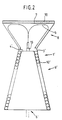
- a variant 1 ′ of the finger 1 comprises a first part 8 identical to the part 8 of the finger 1, the diffuser 15 sprinkling the inner part of the face 7, supporting the detector carrier plate 70.
- a second part 9 ′, closest to the base 6 ′ of the finger 1 ′, is of cross section which increases progressively as it approaches the base 6 ′.
- the part 9 ′ is a truncated cone, and the finger 1 ′ is therefore formed of two truncated cones 8 and 9 ′ connected by their narrowest parts. This makes it possible to give the exchanger 10 ′ a flared shape like the part 9, thus increasing the surface of exchange with the expanded gases, in the zone where these are at relatively low pressure.
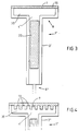
- such a cooler is a machine in which cooling is obtained from a thermodynamic cycle based on the compression and decompression of a gas, in particular helium, using a heat exchanger or regenerator.
- the exchanger is designated by the reference 20.
- the must 1 ⁇ always includes a first part 8 adjacent to the outer face 7, whose cross section decreases away from this outer face.
- the part 8 of the finger of FIG. 3 decreases in a relatively abrupt way to avoid creating an excessively large conical volume, behaving like a dead volume coming to reduce performance and disrupt cooler operation.
- the volume between the outer face 7 and the exchanger 20 is filled with helium which thus forms a layer, the high thermal conductivity makes it possible to standardize the temperature of the plate 70.
- helium which thus forms a layer
- the flaring of the part 8 is not necessarily as abrupt as in FIG. 3, and it is determined to improve the heat exchanges between the plate 70 without degrading the thermodynamic efficiency of the cooler.
Landscapes
- Engineering & Computer Science (AREA)
- Physics & Mathematics (AREA)
- Mechanical Engineering (AREA)
- Thermal Sciences (AREA)
- General Engineering & Computer Science (AREA)
- Chemical & Material Sciences (AREA)
- Combustion & Propulsion (AREA)
- Radiation Pyrometers (AREA)
- Photometry And Measurement Of Optical Pulse Characteristics (AREA)
- Containers, Films, And Cooling For Superconductive Devices (AREA)
Claims (7)
- Hohler Kühlzapfen (1, 1′, 1˝) für einen Halbleiterschaltkreis (2a, 2b), dessen Wandung (3, 3′, 3˝) ein Innenvolumen (4, 4′, 4˝) abgrenzt, welches zur Aufnahme eines Tieftemperaturfluids (5) bestimmt ist, das durch das Unterteil (6, 6′, 6˝) des Zapfens eingeleitet wird, und dessen freier Endabschnitt eine Außenseite (7) in thermischen Kontakt mit dem zu kühlenden Schaltkreis (2a, 2b) aufweist, dadurch gekennzeichnet, daß der Zapfen benachbart zur Außenseite (7) einen ersten Abschnitt (8) aufweist, dessen Querschnittsfläche mit zunehmendem Abstand von der Außenseite (7) abnimmt.
- Kühlzapfen nach Anspruch 1, dadurch gekennzeichnet, daß das Tieftemperaturfluid (5) durch eine Joule-Thomson-Entspannungskühlvorrichtung geliefert wird, die mit einem Wärmetauscher (10′) versehen ist, welcher in einem zweiten Abschnitt (9) des Zapfens in der Nähe seines Unterteils (6) untergebracht ist, wobei der Querschnitt des zweiten Abschnitts (9′) sowie der Querschnitt des Wärmetauschers (10′) mit abnehmendem Abstand zum Unterteil (6′) des Zapfens allmählich zunehmen.
- Kühlzapfen nach Anspruch 1, dadurch gekennzeichnet, daß das Tieftemperaturfluid durch eine Kühlvorrichtung mit geschlossenem Kreislauf erzeugt wird, die mit einem Wärmetauscher (20) versehen ist, welcher in dem Volumen (4˝) untergebracht ist, wobei zwischen der Außenseite (7) und dem Wärmetauscher (20) eine Schicht (30) thermisch leitenden Gases vorhanden ist.
- Kühlfinger nach Anspruch 3, dadurch gekennzeichnet, daß die Wandung (3˝) in ihrem der Außenseite (7) entsprechendem Abschnitt mit Nuten (72) versehen ist, um die Oberfläche für den Wärmetausch mit der Schicht thermisch leitenden Gases zu vergrößern.
- Kühlzapfen nach Anspruch 3 oder 4, dadurch gekennzeichnet, daß das Gas der Schicht (30) Helium ist.
- Kühlzapfen nach einem der Ansprüche 1 bis 5, dadurch gekennzeichnet, daß die Schaltung einen Detektor (2a) für Infrarotstrahlung aufweist, wobei eine kalte Blende (81) vorhanden ist, die mit dem ersten Abschnitt (8) ein Teil bildet.
- Tieftemperatureinrichtung, dadurch gekennzeichnet, daß sie einen Kühlzapfen nach einem der Ansprüche 1 bis 6 aufweist.
Applications Claiming Priority (2)
| Application Number | Priority Date | Filing Date | Title |
|---|---|---|---|
| FR9016454 | 1990-12-28 | ||
| FR9016454A FR2671230B1 (fr) | 1990-12-28 | 1990-12-28 | Doigt de refroidissement d'un circuit semi-conducteur et dispositif cryogenique pourvu d'un tel doigt. |
Publications (2)
| Publication Number | Publication Date |
|---|---|
| EP0493208A1 EP0493208A1 (de) | 1992-07-01 |
| EP0493208B1 true EP0493208B1 (de) | 1995-08-09 |
Family
ID=9403816
Family Applications (1)
| Application Number | Title | Priority Date | Filing Date |
|---|---|---|---|
| EP91403455A Expired - Lifetime EP0493208B1 (de) | 1990-12-28 | 1991-12-19 | Kühlfinger für Halbleiterschaltung und kryogenische Anordnung mit solchem Finger |
Country Status (4)
| Country | Link |
|---|---|
| EP (1) | EP0493208B1 (de) |
| DE (1) | DE69112010T2 (de) |
| ES (1) | ES2077200T3 (de) |
| FR (1) | FR2671230B1 (de) |
Families Citing this family (5)
| Publication number | Priority date | Publication date | Assignee | Title |
|---|---|---|---|---|
| US6140141A (en) * | 1998-12-23 | 2000-10-31 | Sun Microsystems, Inc. | Method for cooling backside optically probed integrated circuits |
| FR2834127B1 (fr) | 2001-12-26 | 2005-01-14 | Sagem | Photodetecteur refroidi |
| FR2856522B1 (fr) * | 2003-06-20 | 2005-08-19 | Sagem | Photodetecteur refroidi |
| FR2860637B1 (fr) * | 2003-10-01 | 2005-12-02 | Sagem | Dispositif de support d'un detecteur |
| CN108895696B (zh) * | 2018-06-08 | 2020-06-09 | 上海理工大学 | 具有锯齿形微通道节流制冷器的复合冷却装置及设备 |
Family Cites Families (4)
| Publication number | Priority date | Publication date | Assignee | Title |
|---|---|---|---|---|
| US4344302A (en) * | 1981-06-08 | 1982-08-17 | Hughes Aircraft Company | Thermal coupling structure for cryogenic refrigeration |
| US4950181A (en) * | 1988-07-28 | 1990-08-21 | Ncr Corporation | Refrigerated plug-in module |
| FR2638023B1 (fr) * | 1988-10-13 | 1992-07-31 | Telecommunications Sa | Dispositif cryostatique pour detecteur de rayonnements |
| DE3851335D1 (de) * | 1988-12-05 | 1994-10-06 | Heinz Karl Diedrich | Vakuumbehälter zum kryogenischen Kühlen einer Packung für eine elektronische Anordnung. |
-
1990
- 1990-12-28 FR FR9016454A patent/FR2671230B1/fr not_active Expired - Fee Related
-
1991
- 1991-12-19 ES ES91403455T patent/ES2077200T3/es not_active Expired - Lifetime
- 1991-12-19 EP EP91403455A patent/EP0493208B1/de not_active Expired - Lifetime
- 1991-12-19 DE DE69112010T patent/DE69112010T2/de not_active Expired - Fee Related
Also Published As
| Publication number | Publication date |
|---|---|
| FR2671230A1 (fr) | 1992-07-03 |
| EP0493208A1 (de) | 1992-07-01 |
| FR2671230B1 (fr) | 1993-04-16 |
| DE69112010D1 (de) | 1995-09-14 |
| DE69112010T2 (de) | 1996-04-11 |
| ES2077200T3 (es) | 1995-11-16 |
Similar Documents
| Publication | Publication Date | Title |
|---|---|---|
| US6621071B2 (en) | Microelectronic system with integral cryocooler, and its fabrication and use | |
| EP0614059B1 (de) | Kühler mit einem Schwingrohrkaltkopf | |
| EP1630531B1 (de) | Bauelement zur Detektion elektromagnetischer Strahlung, insbesondere Infrarot, optische Baugruppe für Infrarotabbildung mit integriertem solchen Bauelement und dessen Herstellungsverfahren | |
| EP3196947B1 (de) | Kühlvorrichtung, die einen verbesserten kryostatfinger umfasst | |
| EP0947787A1 (de) | Vorrichtung für eine thermische Verbindung in einer kryogenen Maschine | |
| FR2553577A1 (fr) | Boitier pour un composant optoelectronique a semi-conducteurs | |
| EP0493208A1 (de) | Kühlfinger für Halbleiterschaltung und kryogenische Anordnung mit solchem Finger | |
| FR3008825A1 (fr) | Doigt froid ameliore et dispositif de detection comportant le doigt froid | |
| FR2703440A1 (fr) | Refroidisseur miniature de type Stirling pour détecteurs à infrarouge. | |
| FR2586793A1 (fr) | Procede et appareil de refrigeration magnetique | |
| FR2914050A1 (fr) | Refrigerateur a basse ou tres basse temperature et procede de refrigeration | |
| EP0059272A1 (de) | Kryogene Kühlvorrichtung mit verbesserter thermischer Verbindung | |
| FR2634063A1 (fr) | Interface microsonde laser pour spectrometre de masse | |
| FR2878945A1 (fr) | Dispositif de refroidissement | |
| WO2003056632A1 (fr) | Photodetecteur refroidi | |
| FR2723435A1 (fr) | Systeme de refroidisseur cryogenique a bout froid soude | |
| EP0258093A1 (de) | Joule-Thomson-Kühler und mit diesem Kühler versehener Kryostat | |
| EP4291862B1 (de) | System zur detektion elektromagnetischer strahlung und kühlverfahren | |
| FR2540278A1 (fr) | Dispositif de stockage d'energie thermique | |
| EP0494001A1 (de) | Kühlfinger für Halbleiterschaltung und kryogenische Anordnung mit solchem Finger | |
| EP1489665B1 (de) | Gekühlter Photodetektor | |
| FR2587444A1 (fr) | Ligne de transfert de gaz liquefie comportant un ecran thermique muni d'un echangeur | |
| EP0305257A1 (de) | Verfahren und Vorrichtung zur Kryokühlung eines Objekts | |
| FR2725779A1 (fr) | Dispositif cryogenique pour equipements optroniques et/ou electroniques et equipements comprenant un tel dispositif | |
| EP0338920B1 (de) | Joule-Thomson-Kühler mit einem Wärmetauscher aus poröser Masse |
Legal Events
| Date | Code | Title | Description |
|---|---|---|---|
| PUAI | Public reference made under article 153(3) epc to a published international application that has entered the european phase |
Free format text: ORIGINAL CODE: 0009012 |
|
| AK | Designated contracting states |
Kind code of ref document: A1 Designated state(s): DE ES GB IT |
|
| 17P | Request for examination filed |
Effective date: 19921229 |
|
| 17Q | First examination report despatched |
Effective date: 19941021 |
|
| GRAA | (expected) grant |
Free format text: ORIGINAL CODE: 0009210 |
|
| AK | Designated contracting states |
Kind code of ref document: B1 Designated state(s): DE ES GB IT |
|
| REF | Corresponds to: |
Ref document number: 69112010 Country of ref document: DE Date of ref document: 19950914 |
|
| ITF | It: translation for a ep patent filed | ||
| REG | Reference to a national code |
Ref country code: ES Ref legal event code: FG2A Ref document number: 2077200 Country of ref document: ES Kind code of ref document: T3 |
|
| GBT | Gb: translation of ep patent filed (gb section 77(6)(a)/1977) |
Effective date: 19951120 |
|
| PLBE | No opposition filed within time limit |
Free format text: ORIGINAL CODE: 0009261 |
|
| STAA | Information on the status of an ep patent application or granted ep patent |
Free format text: STATUS: NO OPPOSITION FILED WITHIN TIME LIMIT |
|
| 26N | No opposition filed | ||
| REG | Reference to a national code |
Ref country code: GB Ref legal event code: IF02 |
|
| PGFP | Annual fee paid to national office [announced via postgrant information from national office to epo] |
Ref country code: ES Payment date: 20071207 Year of fee payment: 17 |
|
| PGFP | Annual fee paid to national office [announced via postgrant information from national office to epo] |
Ref country code: IT Payment date: 20071212 Year of fee payment: 17 |
|
| PGFP | Annual fee paid to national office [announced via postgrant information from national office to epo] |
Ref country code: GB Payment date: 20071129 Year of fee payment: 17 |
|
| PGFP | Annual fee paid to national office [announced via postgrant information from national office to epo] |
Ref country code: DE Payment date: 20071129 Year of fee payment: 17 |
|
| GBPC | Gb: european patent ceased through non-payment of renewal fee |
Effective date: 20081219 |
|
| PG25 | Lapsed in a contracting state [announced via postgrant information from national office to epo] |
Ref country code: DE Free format text: LAPSE BECAUSE OF NON-PAYMENT OF DUE FEES Effective date: 20090701 |
|
| PG25 | Lapsed in a contracting state [announced via postgrant information from national office to epo] |
Ref country code: GB Free format text: LAPSE BECAUSE OF NON-PAYMENT OF DUE FEES Effective date: 20081219 |
|
| REG | Reference to a national code |
Ref country code: ES Ref legal event code: FD2A Effective date: 20081220 |
|
| PG25 | Lapsed in a contracting state [announced via postgrant information from national office to epo] |
Ref country code: ES Free format text: LAPSE BECAUSE OF NON-PAYMENT OF DUE FEES Effective date: 20081220 |
|
| PG25 | Lapsed in a contracting state [announced via postgrant information from national office to epo] |
Ref country code: IT Free format text: LAPSE BECAUSE OF NON-PAYMENT OF DUE FEES Effective date: 20081219 |