EP0493941B1 - Support pour moteur actionné par ondes de vibration - Google Patents
Support pour moteur actionné par ondes de vibration Download PDFInfo
- Publication number
- EP0493941B1 EP0493941B1 EP91311841A EP91311841A EP0493941B1 EP 0493941 B1 EP0493941 B1 EP 0493941B1 EP 91311841 A EP91311841 A EP 91311841A EP 91311841 A EP91311841 A EP 91311841A EP 0493941 B1 EP0493941 B1 EP 0493941B1
- Authority
- EP
- European Patent Office
- Prior art keywords
- vibration
- supporting member
- supporting
- end portion
- vibrating body
- Prior art date
- Legal status (The legal status is an assumption and is not a legal conclusion. Google has not performed a legal analysis and makes no representation as to the accuracy of the status listed.)
- Expired - Lifetime
Links
- 238000006073 displacement reaction Methods 0.000 claims description 15
- 238000005452 bending Methods 0.000 claims description 8
- 230000003068 static effect Effects 0.000 claims description 4
- 239000012858 resilient material Substances 0.000 claims 1
- 238000010168 coupling process Methods 0.000 description 15
- 230000008878 coupling Effects 0.000 description 14
- 238000005859 coupling reaction Methods 0.000 description 14
- 238000010586 diagram Methods 0.000 description 7
- 230000000694 effects Effects 0.000 description 3
- 230000007935 neutral effect Effects 0.000 description 3
- 230000015572 biosynthetic process Effects 0.000 description 2
- 238000006243 chemical reaction Methods 0.000 description 2
- 238000003754 machining Methods 0.000 description 2
- 239000000463 material Substances 0.000 description 2
- 230000002093 peripheral effect Effects 0.000 description 2
- 238000010008 shearing Methods 0.000 description 2
- 238000003466 welding Methods 0.000 description 2
- 239000000853 adhesive Substances 0.000 description 1
- 230000001070 adhesive effect Effects 0.000 description 1
- 230000002411 adverse Effects 0.000 description 1
- 230000005684 electric field Effects 0.000 description 1
- 238000009413 insulation Methods 0.000 description 1
- 239000011295 pitch Substances 0.000 description 1
- 230000000644 propagated effect Effects 0.000 description 1
- 230000002787 reinforcement Effects 0.000 description 1
- 238000003786 synthesis reaction Methods 0.000 description 1
- 230000002463 transducing effect Effects 0.000 description 1
Images


Classifications
-
- H—ELECTRICITY
- H02—GENERATION; CONVERSION OR DISTRIBUTION OF ELECTRIC POWER
- H02N—ELECTRIC MACHINES NOT OTHERWISE PROVIDED FOR
- H02N2/00—Electric machines in general using piezoelectric effect, electrostriction or magnetostriction
- H02N2/10—Electric machines in general using piezoelectric effect, electrostriction or magnetostriction producing rotary motion, e.g. rotary motors
- H02N2/16—Electric machines in general using piezoelectric effect, electrostriction or magnetostriction producing rotary motion, e.g. rotary motors using travelling waves, i.e. Rayleigh surface waves
- H02N2/163—Motors with ring stator
Definitions
- the present invention relates to a vibration wave driven motor which causes a vibrating body and a member being in contact with the aforesaid vibrating body to exert relative motion by the traveling vibration wave generated by the vibrating body. More particularly, the invention relates to a supporting device capable of supporting the vibrating body to be fixed to fixing members without any interference to its vibration.
- the vibration wave driven motor which utilizes traveling vibration waves has been in practical use recently, and the summary of its principle is given below.
- piezoelectric element group A and piezoelectric element group B there are fixed two groups of plural piezoelectric elements (hereinafter referred to as piezoelectric element group A and piezoelectric element group B) arranged in the peripheral direction to form a stator. These piezoelectric elements are arranged in each of the groups A and B at pitches of ⁇ /2 with alternately inverted stretches. Also, there is arranged a deviation of ⁇ /4 times an odd number between the groups A and B. For both of the A and B group piezoelectric elements, electrode films are provided respectively.
- standing wave A an out-of-plane vibration
- standing wave A a flexural vibration such as having antinode positions in the central portions of each of the piezoelectric elements in the aforesaid group A and at every other points ⁇ /2 away therefrom as well as node positions in the central points between the aforesaid antinode positions.
- the antinode and node positions thereof are deviated by ⁇ /4 with respect to the aforesaid standing wave A. If an a.c. voltage of same frequency with time phase difference of ⁇ /4 is applied to both of the groups A and B simultaneously, then the flexural vibration having a traveling wave (wavelength ⁇ ) which travels in the circumferential direction is generated as a result of the synthesis of the two standing waves. At this juncture, each of the points on the other face of the above-mentioned vibrating body which has a thickness is caused to create a kind of elliptic motion.
- the vibrating body for supporting the traveling vibration wave driven motor because there is no point in the vibrating body, which is not displaced, i.e., there is no node of the vibration therein. Accordingly, the vibrating body is fixed to a fixing member through a flexible material such as felt.
- EP-A-0360199 discloses a vibration wave driven apparatus comprising a vibration member for generating a travelling wave and a support arrangement for supporting the vibration member.
- the support arrangement comprises a first support member arranged parallel to the direction of travel of the travelling wave and supported at its centre.
- Two second support members are arranged perpendicular to the direction of travel of the travelling wave at ends of the first support member and in contact with the vibration member. This arrangement is however of reduced efficiency because the torsional displacement of the vibration member is not followed.
- the present invention provides a vibration wave driven apparatus comprising:
- One embodiment of the present invention provides a vibration wave driven apparatus having a supporting device for supporting a vibrating body at one or plural locations where the aforesaid vibrating body is caused to generate traveling waves by applying an alternating electric field to an electromechanical energy transducing element which is connected to the vibrating body thereby to move relatively the aforesaid vibrating body and a contacting member which is in contact under pressure with the aforesaid vibrating body.
- the supporting device has a first supporting member which extends in the direction substantially perpendicular to the traveling direction of the traveling vibration wave and one end of which is coupled to the aforesaid vibrating body or contacting member, and a second supporting member which extends in the traveling direction of the traveling vibration wave and one end of which is coupled to the other end of the aforesaid first supporting member and the other end of which is connected to a fixing portion.
- Fig. 1 is a perspective view schematically illustrating a first embodiment of the supporting device for a vibration wave driven motor according to the present invention
- Fig. 2 is a perspective view showing the detail thereof.
- what differs from the known vibration wave driven motor will be referred to in the description set forth below.
- Supporting devices 20 is arranged to support the known circular vibrating body 1, which is vibrated by the traveling wave having a wavelength ⁇ , at three locations as shown in Fig. 2, and the devices are respectively provided on the outer periphery of the vibrating body 1.
- the vibrating body 1 is arranged to obtain a strong driving force by lowering the position of the neutral axis of vibration, for example, with the formation of plural projections on the side which is in contact with the known traveling body 1A (Fig. 4), and on the opposite face of the projective surface, the known piezoelectric element 1' is bonded by adhesives. Then, by applying the known a.c. voltage to the two-phase piezoelectric element group formed on this piezoelectric element 1', the vibrating body 1 is caused to generate an out-of-plane mode traveling wave with a wavelength ⁇ in the circumferential direction.
- a reference numeral 2 designates a first supporting member which extends from the end face of the vibrating body 1 in the direction at right angles or almost right angles to the traveling direction of the traveling wave, and in the present embodiment, the supporting member is of a resilient rod type having an effective length l 1 .
- This effective length l 1 is defined to be a length thereby to allow the first supporting member to vibrate following the torsional displacement of the vibrating body 1.
- a reference numeral 3 designates a second supporting member which is connected to the rod type resilient member 2 having an effective length of l 2 extending in parallel or almost in parallel to the traveling direction of the traveling wave generated in the vibrating body 1, and the other end thereof is fixed to a fixing section 4.
- This length l 2 is defined to be a length thereby to allow the second supporting member to vibrate following the amplitude of the traveling wave as well as the torsion of the first supporting member around its axis at the connecting portion of the first supporting member and second supporting member.
- the first supporting member does not satisfy the aforesaid conditions due to its rigidity, for example, the aforesaid second body should be able to satisfy the aforesaid conditions and the aforesaid conditions required for the first supporting member as well.
- the operation is performed to support the device by the utilization of the resilient deformation of the first and second supporting members 2 and 3 without producing any adverse effect on the traveling wave.
- the description will be made thereof separately according to the functions represented by the first and second supporting members. In this respect, the details of the principle will also be described hereunder.
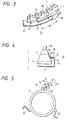
- FIG. 3 illustrates a second embodiment according to the present invention.
- Fig. 4 is a cross-sectional view illustrating the junction of the supporting member and vibrating body.
- Fig. 5 is a plan view showing the supporting member.
- the supporting member is produced from a plate by a press or other machining and formed by bending the portions indicated by broken lines in Fig. 5.
- the supporting member 21 is constructed by a set of three similar members of a circular arc type, which are integrally coupled by a base 11.
- a reference numeral 13 designates a first supporting member corresponding to the first supporting member 2 shown in Fig. 2; 14, a second supporting member corresponding to the second supporting member 3 shown in Fig. 2; and 11 and 15, fixing portions.
- the supporting member coupling portion 12 formed by bending the leading end of the first supporting member 13 is connected.
- This coupling method is implemented by a bonding, spot welding, laser welding, or the like.
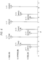
- Fig. 6 is a diagram showing the relationships between the typical beam vibration modes and constant ⁇ . However, in this diagram, the respective cases are shown, in which with one end being fixed (displacement: zero, deflection angle: zero), (a) becomes a free end (bending moment: zero, shearing force: zero); (b), antinode end (deflection angle: zero, shearing force: zero); and (c), node end (displacement: zero, bending moment: zero) depending on the boundary conditions of the remaining one end.
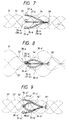
- Fig. 7, Fig. 8, and Fig. 9 are the diagrams each showing the relationship between the vibration (displacement) of the second supporting member 14 and the traveling wave.
- Fig. 7 illustrates the case where the second supporting member 14 becomes antinode at the coupling position to the vibrating body 1, which represents the case of the lowest mode order indicated by (b-1) in Fig. 6.
- the traveling wave of the vibrating body 1 is illustrated by the lines of a sinusoidal waveform type, and as its typical examples, the representations are made for phase 0° (dashed line 31), phase 90° (dotted line 32), phase 180° (two-dot chain line 33), and phase 270° (broken line 34).
- the one end of the second supporting member 14 is shown as the fixed end 39 (corresponding to the fixing portion 11 or 15 in Fig. 3 through Fig. 5).
- Reference marks 35-a, 36-a, 37-a, and 38-a designate the positions of the coupling portion 12 to the vibrating body 1 at the phases 0° through 270°; 35-b, 36-b, 37-b, and 38-b, the vibrating modes of the second supporting member 14 at the phases 0° through 270°.
- the coupling portion 12 designated by the reference mark 36-a (38-a) does not show any deformation associated with the traveling wave 32 (34). Accordingly, the traveling wave is blocked by the torsional force of the supporting member 14. It is therefore necessary to weaken this torsional force with the torsional deformation of the first supporting member 13 by defining the length l 1 of the supporting member 13 as described earlier. In other words, the torsional rigidity of the first supporting member 13 should be reduced.
- Fig. 8 illustrates the case where the second supporting member 14 becomes node at the coupling position to the vibrating body 1, which shows the case of the lowest mode order indicated by (c-1) in Fig. 6.
- Each portion at the phases 0° through 270° of the traveling wave is the same as shown in Fig. 7 and indicated by the same numbers (marks) with ' (dash).
- the deformation of the second supporting member 14 follows the torsional force of the traveling wave at the coupling portion to the vibrating body 1.
- the traveling wave at each of the phases 31', 32', 33', and 34' is fluctuated vertically because the displacement of the second supporting member 14 is zero at the coupling portion. Accordingly, the vertical vibration is given to the moving member (not shown) which is in contact under pressure with the vibrating body 1 to lower the motor efficiency due to the slipping of the contacting portion or to create a problem of noise generation.
- Fig. 9 illustrates the case where the second supporting member 14 is deformed intermediately between the antinode and node at the coupling positions to the vibrating body 1, which represents the vibrating modes indicated by the reference marks (b-1) and (c-1) in Fig. 6, and the affecting degrees of the respective modes are determined by ⁇ .
- the representation is made by the mark " (two dashes) attached to the elements having the same functions or lines indicating the same contents.
- the deformation of the second supporting member 14 follows not only the torsion but displacement of the vibrating body 1, i.e., the amplitude of the vibrating body 1, at the coupling portions to the first and second supporting members.
- Fig. 10 is a partially enlarged view showing a third embodiment.
- Fig. 11 is a cross-sectional view illustrating the junction of the supporting member and vibrating body.
- Fig. 12 is a plan view showing the supporting member.
- a supporting member 47 is produced from a plate by a press or other machining and formed by bending it at portions indicated by broken lines in Fig. 12.
- the supporting member 47 is constructed by three sets of a similar member of a circular arc type which are integrally coupled by a base 46.
- a reference numeral 42 designates a first supporting member; 43, a second supporting member; 44 and 46, fixing portions; and 45, a bending portion for reinforcement.
- a groove 40-a is provided for mounting the supporting member, and the coupling portion 41 of the supporting member is fitted thereinto for the junction.
- the first supporting member 42 is of a shape extending in the thrust direction and is arranged substantially perpendicular to the traveling direction of the traveling wave.
- each dimension such as l 1 and l 2 is determined on the basis of the same principle in the second embodiment.
- the vibrating body is supported by the three sets of the supporting member, but as its principle shows, the numbers, directions, and combinations thereof are arbitrary.
- the coupling portions of the vibrating body to the supporting member are not limited to the shape represented in the present embodiment, and the shapes can be of a hole, groove, projection, flange, or other type. Further, its coupling position is not confined to the vicinity of the neutral axis of the peripheral side of the vibrating body. The same effect can be obtained also in the inner side of the periphery or the bottom face of the non-neutral axis (including the plane of piezoelectric element), projective portion, or bottom face of the groove portion.
- the present invention is applicable to a linear type vibration wave driven motor as well as to the ring type motor.
- the vibrating body is supported.
- the traveling waves of the vibrating body are propagated to the movable member (not shown) which is in contact under pressure therewith, it may be possible to apply the same supporting structure as shown in each of the above-embodiments to the coupling portion of the output shafts of the vibrating body and the movable member.
- a vibration wave driven apparatus comprising a device for supporting vibration member according to the present invention as claimed is provided with a first supporting member which is arranged in the direction essentially perpendicular to the traveling direction of the traveling wave and a second supporting member which is arranged essentially in parallel to the aforesaid traveling direction, and by defining the length of each of them as described earlier, it is possible for them to support the vibration member reliably without any loss of the vibrating energy as well as to enhance the vibration wave driven apparatus efficiency. Furthermore, the supporting structure can be made small so that the apparatus is constructed compactly as a whole.
Landscapes
- General Electrical Machinery Utilizing Piezoelectricity, Electrostriction Or Magnetostriction (AREA)
Claims (10)
- Appareil actionné par ondes vibratoires comportant :caractérisé en ce queun élément à vibration (1, 40) destiné à générer une onde progressive se déplaçant dans une première direction ; etdes moyens de support (20, 2, 3, 12, 13, 14, 41, 42, 43, 45) destinés à supporter ledit élément (1, 40) à vibration ;lesdits moyens de support (20, 2, 3, 12, 13, 14, 15, 41, 42, 43, 44, 45) comprennent un premier élément de support (2, 12, 13, 41, 42) et un second élément de support (3, 14, 43) ;ledit premier élément de support (2, 12, 13, 41, 42) ayant une première partie extrême (12, 41) et une seconde partie extrême (13, 42), ladite première partie extrême (12, 41) étant couplée à l'élément à vibration (1, 40), ledit premier élément de support (2, 12, 13, 41, 42) étant disposé dans une direction sensiblement normale à ladite première direction, et ledit premier élément de support (2, 12, 13, 41, 42) ayant une longueur prédéterminée (l1), de manière qu'une vibration dans cet élément suive un déplacement en torsion dudit élément à vibration (1, 41) provoqué par ladite onde progressive ; etledit second élément de support (3, 14, 43) ayant une première partie extrême couplée à ladite seconde partie extrême (13, 42) dudit premier élément de support (2, 12, 13, 41, 42) et une seconde partie extrême fixée à un élément (11, 15, 44, 46) de fixation, ledit second élément de support (3, 14, 43) étant agencé sensiblement dans ladite première direction, ledit second élément (3, 14, 43) de support ayant en outre une longueur prédéterminée (l2), de manière qu'une vibration dans cet élément suive une amplitude de ladite onde progressive et la vibration dans ladite seconde partie extrême (13, 42) dudit premier élément de support (2, 12, 13, 41, 42) provoquée par ledit déplacement en torsion dudit élément à vibration (1, 40).
- Appareil actionné par ondes vibratoires selon la revendication 1, dans lequel ledit premier élément de support (2, 12, 13, 41, 42) est disposé dans une direction sensiblement normale à ladite première direction et sensiblement normale à une direction de vibration dudit élément (1, 40) à vibration, et est soumis à une torsion entre ladite première partie extrême (12, 41) et ladite seconde partie extrême (13, 42).
- Appareil actionné par ondes vibratoires selon la revendication 1, dans lequel ledit premier élément de support (2, 12, 13, 41, 42) est disposé dans une direction sensiblement normale à ladite première direction et sensiblement parallèle à une direction de vibration dudit élément (1, 40) à vibration, et est soumis à une flexion entre ladite première partie extrême (12, 41) et ladite seconde partie extrême (13, 42).
- Appareil actionné par ondes vibratoires selon l'une quelconque des revendications précédentes, dans lequel ledit premier élément de support (12, 13, 41, 42) et ledit second élément de support (14, 43) sont structurés de façon intégrée.
- Appareil actionné par ondes vibratoires selon l'une quelconque des revendications précédentes, comportant en outre
un élément de contact placé en contact de frottement avec l'élément à vibration (1, 41) et actionné par ladite onde progressive. - Appareil actionné par ondes vibratoires selon la revendication 5, dans lequel ledit second élément de support (3, 14, 43) est formé d'une matière élastique et est disposé de façon à exercer une pression entre ledit élément vibrant (1, 40) et ledit élément de contact en utilisant la déformation élastique statique dudit second élément de support (3, 14, 43).
- Appareil actionné par ondes vibratoires selon l'une quelconque des revendications précédentes, dans lequel ledit élément (1, 40) à vibration est de forme sensiblement circulaire.
- Appareil actionné par ondes vibratoires selon l'une quelconque des revendications précédentes, comportant plusieurs desdits moyens de support espacés (20, 23, 12, 13, 14, 41, 42, 43, 45) destinés à supporter ledit élément à vibration (1, 40) en plusieurs emplacements.
- Appareil actionné par ondes vibratoires selon l'une quelconque des revendications 5 à 8, dans lequel un côté dudit élément à vibration (1, 40) qui est en contact avec ledit élément de contact est pourvu de plusieurs saillies.
- Appareil actionné par ondes vibratoires selon l'une quelconque des revendications 4 à 9, dans lequel ledit premier élément de support (12, 13, 41, 42) et ledit second élément de support (14, 43) sont formés de façon intégrée par un travail à la presse.
Applications Claiming Priority (2)
| Application Number | Priority Date | Filing Date | Title |
|---|---|---|---|
| JP2405834A JPH04222475A (ja) | 1990-12-25 | 1990-12-25 | 振動波モータの支持装置 |
| JP405834/90 | 1990-12-25 |
Publications (2)
| Publication Number | Publication Date |
|---|---|
| EP0493941A1 EP0493941A1 (fr) | 1992-07-08 |
| EP0493941B1 true EP0493941B1 (fr) | 1998-04-29 |
Family
ID=18515443
Family Applications (1)
| Application Number | Title | Priority Date | Filing Date |
|---|---|---|---|
| EP91311841A Expired - Lifetime EP0493941B1 (fr) | 1990-12-25 | 1991-12-20 | Support pour moteur actionné par ondes de vibration |
Country Status (4)
| Country | Link |
|---|---|
| US (1) | US5264753A (fr) |
| EP (1) | EP0493941B1 (fr) |
| JP (1) | JPH04222475A (fr) |
| DE (1) | DE69129327T2 (fr) |
Families Citing this family (9)
| Publication number | Priority date | Publication date | Assignee | Title |
|---|---|---|---|---|
| JPH0421374A (ja) * | 1990-05-15 | 1992-01-24 | Canon Inc | 振動波モータ及びプリンタ |
| JPH05252764A (ja) * | 1992-03-05 | 1993-09-28 | Nikon Corp | 超音波モータ |
| US5319278A (en) * | 1992-06-05 | 1994-06-07 | Nec Corporation | Longitudinal-torsional resonance ultrasonic motor with improved support structure |
| FR2695767B1 (fr) * | 1992-09-17 | 1994-10-21 | Mecanique Appliquee Lab | Moteur piézo-électrique rotatif présentant une liaison stator-boîtier améliorée. |
| DE19757528C2 (de) * | 1997-12-23 | 2000-08-10 | Bosch Gmbh Robert | Lagerung für einen Schwingungsantrieb |
| TW571505B (en) * | 2001-08-09 | 2004-01-11 | Asulab Sa | Piezoelectric motor |
| US7332029B2 (en) * | 2002-01-18 | 2008-02-19 | Neuro Probe Incorporated | Crystal forming apparatus and method for using same |
| CN106165288B (zh) * | 2014-04-02 | 2019-05-21 | Pcb电机公司 | 定子和电机 |
| JP6995660B2 (ja) * | 2018-02-15 | 2022-01-14 | キヤノン株式会社 | 振動波モータを備えた駆動装置 |
Family Cites Families (9)
| Publication number | Priority date | Publication date | Assignee | Title |
|---|---|---|---|---|
| FR2127184A5 (fr) * | 1971-02-26 | 1972-10-13 | Cepe | |
| CH581405A5 (fr) * | 1974-03-29 | 1976-10-29 | Suisse Horlogerie | |
| US4025806A (en) * | 1975-07-14 | 1977-05-24 | Societe Suisse Pour L'industrie Horlogere Management Services S.A. | Suspension and package for piezo-electric resonators |
| US4410827A (en) * | 1980-04-24 | 1983-10-18 | Kabushiki Kaisha Suwa Seikosha | Mode coupled notched tuning fork type quartz crystal resonator |
| JPS6096183A (ja) * | 1983-10-26 | 1985-05-29 | Canon Inc | 振動波モータ |
| US4649311A (en) * | 1984-04-02 | 1987-03-10 | Canon Kabushiki Kaisha | Vibration wave motor |
| JPS62213585A (ja) * | 1986-03-12 | 1987-09-19 | Canon Inc | 振動波モ−タ |
| JPS63136983A (ja) * | 1986-11-26 | 1988-06-09 | Canon Inc | 振動波モ−タ |
| JP2612050B2 (ja) * | 1988-09-19 | 1997-05-21 | キヤノン株式会社 | 振動波モータ |
-
1990
- 1990-12-25 JP JP2405834A patent/JPH04222475A/ja active Pending
-
1991
- 1991-12-20 US US07/810,904 patent/US5264753A/en not_active Expired - Lifetime
- 1991-12-20 DE DE69129327T patent/DE69129327T2/de not_active Expired - Fee Related
- 1991-12-20 EP EP91311841A patent/EP0493941B1/fr not_active Expired - Lifetime
Also Published As
| Publication number | Publication date |
|---|---|
| JPH04222475A (ja) | 1992-08-12 |
| EP0493941A1 (fr) | 1992-07-08 |
| US5264753A (en) | 1993-11-23 |
| DE69129327D1 (de) | 1998-06-04 |
| DE69129327T2 (de) | 1998-09-03 |
Similar Documents
| Publication | Publication Date | Title |
|---|---|---|
| US4580073A (en) | Vibration wave motor with plural projection vibrator | |
| US4587452A (en) | Vibration wave motor having a vibrator of non-uniform elastic modulus | |
| US5134334A (en) | Ultrasonic linear motor | |
| US4692652A (en) | Vibration wave motor | |
| JP2993702B2 (ja) | 振動波駆動装置 | |
| EP1122878B1 (fr) | Element d'entraînement piézoélectrique pour moteurs à ultrasons | |
| EP0598710B1 (fr) | Dispositf fonctionnant au moyen d'ondes vibratoires et imprimante du type à jet utilisant un tel dispositif | |
| JP2612050B2 (ja) | 振動波モータ | |
| US5264753A (en) | Supporting device for vibration wave driven motor | |
| JP4435695B2 (ja) | 圧電モータの動作方法および固定子を有する中空円筒形の発振器の形状をなす圧電モータ | |
| JPH0510912B2 (fr) | ||
| US5698930A (en) | Ultrasonic wave motor and method of manufacture | |
| KR930009211A (ko) | 초음파 모우터 | |
| KR100318861B1 (ko) | 평판형선형초음파모터 | |
| JPH0421374A (ja) | 振動波モータ及びプリンタ | |
| JP2507083B2 (ja) | 超音波モ―タ | |
| JPH0270277A (ja) | 超音波モータ | |
| JPH08149862A (ja) | 超音波振動子 | |
| JPH0632570B2 (ja) | 振動波モ−タ | |
| JPS63268476A (ja) | 振動波モ−タ | |
| JP2625653B2 (ja) | 振動波モータ | |
| JPH0552137B2 (fr) | ||
| JP2672154B2 (ja) | 振動波駆動装置 | |
| JPH09117166A (ja) | 超音波モータ | |
| JP4654583B2 (ja) | 振動波モータ |
Legal Events
| Date | Code | Title | Description |
|---|---|---|---|
| PUAI | Public reference made under article 153(3) epc to a published international application that has entered the european phase |
Free format text: ORIGINAL CODE: 0009012 |
|
| AK | Designated contracting states |
Kind code of ref document: A1 Designated state(s): DE FR GB |
|
| 17P | Request for examination filed |
Effective date: 19921125 |
|
| 17Q | First examination report despatched |
Effective date: 19950526 |
|
| GRAG | Despatch of communication of intention to grant |
Free format text: ORIGINAL CODE: EPIDOS AGRA |
|
| GRAG | Despatch of communication of intention to grant |
Free format text: ORIGINAL CODE: EPIDOS AGRA |
|
| GRAH | Despatch of communication of intention to grant a patent |
Free format text: ORIGINAL CODE: EPIDOS IGRA |
|
| GRAH | Despatch of communication of intention to grant a patent |
Free format text: ORIGINAL CODE: EPIDOS IGRA |
|
| GRAA | (expected) grant |
Free format text: ORIGINAL CODE: 0009210 |
|
| AK | Designated contracting states |
Kind code of ref document: B1 Designated state(s): DE FR GB |
|
| REF | Corresponds to: |
Ref document number: 69129327 Country of ref document: DE Date of ref document: 19980604 |
|
| EN | Fr: translation not filed | ||
| EN | Fr: translation not filed |
Free format text: BO98/39 PAGES:245, IL Y A LIEU DE SUPPRIMER: LA MENTION DE LA NON REMISE DE CETTE TRADUCTION LA MENTION DE LA REMISE DE CETTE TRADUCTION EST PUBLIEE DANS LE PRESENT BOPI |
|
| ET | Fr: translation filed | ||
| PLBE | No opposition filed within time limit |
Free format text: ORIGINAL CODE: 0009261 |
|
| STAA | Information on the status of an ep patent application or granted ep patent |
Free format text: STATUS: NO OPPOSITION FILED WITHIN TIME LIMIT |
|
| 26N | No opposition filed | ||
| REG | Reference to a national code |
Ref country code: GB Ref legal event code: IF02 |
|
| PGFP | Annual fee paid to national office [announced via postgrant information from national office to epo] |
Ref country code: DE Payment date: 20081231 Year of fee payment: 18 |
|
| PGFP | Annual fee paid to national office [announced via postgrant information from national office to epo] |
Ref country code: GB Payment date: 20081224 Year of fee payment: 18 |
|
| PGFP | Annual fee paid to national office [announced via postgrant information from national office to epo] |
Ref country code: FR Payment date: 20081222 Year of fee payment: 18 |
|
| GBPC | Gb: european patent ceased through non-payment of renewal fee |
Effective date: 20091220 |
|
| REG | Reference to a national code |
Ref country code: FR Ref legal event code: ST Effective date: 20100831 |
|
| PG25 | Lapsed in a contracting state [announced via postgrant information from national office to epo] |
Ref country code: FR Free format text: LAPSE BECAUSE OF NON-PAYMENT OF DUE FEES Effective date: 20091231 |
|
| PG25 | Lapsed in a contracting state [announced via postgrant information from national office to epo] |
Ref country code: DE Free format text: LAPSE BECAUSE OF NON-PAYMENT OF DUE FEES Effective date: 20100701 |
|
| PG25 | Lapsed in a contracting state [announced via postgrant information from national office to epo] |
Ref country code: GB Free format text: LAPSE BECAUSE OF NON-PAYMENT OF DUE FEES Effective date: 20091220 |