EP0493986A2 - Appareil de transmission et réception numérique pour un casque d'écoute sans fil - Google Patents
Appareil de transmission et réception numérique pour un casque d'écoute sans fil Download PDFInfo
- Publication number
- EP0493986A2 EP0493986A2 EP91312106A EP91312106A EP0493986A2 EP 0493986 A2 EP0493986 A2 EP 0493986A2 EP 91312106 A EP91312106 A EP 91312106A EP 91312106 A EP91312106 A EP 91312106A EP 0493986 A2 EP0493986 A2 EP 0493986A2
- Authority
- EP
- European Patent Office
- Prior art keywords
- data
- sound signal
- transmitting
- signal
- receiving
- Prior art date
- Legal status (The legal status is an assumption and is not a legal conclusion. Google has not performed a legal analysis and makes no representation as to the accuracy of the status listed.)
- Granted
Links
Images




Classifications
-
- H—ELECTRICITY
- H04—ELECTRIC COMMUNICATION TECHNIQUE
- H04N—PICTORIAL COMMUNICATION, e.g. TELEVISION
- H04N5/00—Details of television systems
- H04N5/44—Receiver circuitry for the reception of television signals according to analogue transmission standards
- H04N5/60—Receiver circuitry for the reception of television signals according to analogue transmission standards for the sound signals
-
- H—ELECTRICITY
- H04—ELECTRIC COMMUNICATION TECHNIQUE
- H04R—LOUDSPEAKERS, MICROPHONES, GRAMOPHONE PICK-UPS OR LIKE ACOUSTIC ELECTROMECHANICAL TRANSDUCERS; ELECTRIC HEARING AIDS; PUBLIC ADDRESS SYSTEMS
- H04R5/00—Stereophonic arrangements
- H04R5/04—Circuit arrangements, e.g. for selective connection of amplifier inputs/outputs to loudspeakers, for loudspeaker detection, or for adaptation of settings to personal preferences or hearing impairments
-
- H—ELECTRICITY
- H04—ELECTRIC COMMUNICATION TECHNIQUE
- H04B—TRANSMISSION
- H04B10/00—Transmission systems employing electromagnetic waves other than radio-waves, e.g. infrared, visible or ultraviolet light, or employing corpuscular radiation, e.g. quantum communication
- H04B10/11—Arrangements specific to free-space transmission, i.e. transmission through air or vacuum
- H04B10/114—Indoor or close-range type systems
-
- H—ELECTRICITY
- H04—ELECTRIC COMMUNICATION TECHNIQUE
- H04R—LOUDSPEAKERS, MICROPHONES, GRAMOPHONE PICK-UPS OR LIKE ACOUSTIC ELECTROMECHANICAL TRANSDUCERS; ELECTRIC HEARING AIDS; PUBLIC ADDRESS SYSTEMS
- H04R2420/00—Details of connection covered by H04R, not provided for in its groups
- H04R2420/07—Applications of wireless loudspeakers or wireless microphones
-
- H—ELECTRICITY
- H04—ELECTRIC COMMUNICATION TECHNIQUE
- H04R—LOUDSPEAKERS, MICROPHONES, GRAMOPHONE PICK-UPS OR LIKE ACOUSTIC ELECTROMECHANICAL TRANSDUCERS; ELECTRIC HEARING AIDS; PUBLIC ADDRESS SYSTEMS
- H04R5/00—Stereophonic arrangements
- H04R5/033—Headphones for stereophonic communication
Definitions
- the present invention relates in general to radio transmitting and receiving apparatus, and more particularly to transmitting and receiving apparatus for a radio headphone.
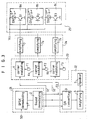
- the illustrated transmitting apparatus comprises a first amplifying circuit 33 including amplifiers 31 and 32 for amplifying respectively a left sound signal L/S and a right sound signal R/S from headphone output of a television set or an audio set by a predetermined amplification degree, a frequency modulating circuit 35 including frequency moculators 35a and 35b for frequency-modulating respectively output signals from the amplifiers 31 and 32 in the first amplifying circuit 33, a first band-pass filtering circuit 36 including band-pass filters 36a and 36b for filtering respectively output signals from the frequency modulators 35a and 35b in the frequency modulating circuit 35 to pass only frequency components of desired band width, and a radio transmitting circuit 37 including a transistor Q4 and a radio transmitting light-emitting diode D5, for transmitting output signals from the band-pass filters 36a and 36b in the first band-pass filtering circuit 36 with infrared rays carrying the
- the illustrated transmitting apparatus comprises a radio receiving circuit 38 including a transistor Q5 and a radio receiving light-receiving diode D8, for receiving signals transmitted from the radio transmitting circuit 37 in the transmitting apparatus and amplifying the received signals by a predetermined amplification degree, a second band-pass filtering circuit 41 including band-pass filters 39 and 40 for filtering respectively output signals from the radio receiving circuit 38 to pass only frequency components of desired band width, a demodulating circuit 44 including demodulators 42 and 43 for demodulating respectively output signals from the band-pass filters 39 and 40 in the second band-pass filtering circuit 41, a second amplifying circuit 47 including amplifiers 45 and 46 for amplifying respectively output signals from the demodulators 42 and 43 in the demodulating circuit 44 by a predetermined amplification degree, and an aural sound output circuit 52 including a switch SW1, resistors R3 and R4, power amplifiers 48 and 49 and headphone speakers
- the left sound signal L/S and the right sound signal R/S through the headphone output of the television set or audio set are weak in level.
- the left sound signal L/S and the right sound signal R/S are amplified by a predetermined amplification degree respectively by the amplifiers 31 and 32 in the first amplifying circuit 33.
- These amplified signals from the amplifiers 31 and 32 are frequency-modulated respectively by the frequency modulators 35a and 35b in the frequency modulating circuit 35 and the frequency-modulated signals from the frequency modulators 35a and 35b are then applied to the band-pass filters 36a and 36b in the first band-pass filtering circuit 36.
- the band-pass filters 36a and 36b Upon receiving the frequency-modulated signals from the frequency modulators 35a and 35b, the band-pass filters 36a and 36b filter respectively the received signals to pass only frequency components of desired band width. Then, the output signals from the band-pass filters 36a and 36b are transmitted to the radio receiving light-receiving diode D8 in the radio receiving circuit 38 in the receiving apparatus through the radio transmitting light-emitting diode D5 in the radio transmitting circuit 37.
- a diode D7 emits a light signal which is indicative of signal transmission.
- a LED driver 34 functions to drive the diode D7.
- the sound signals inputted through the radio receiving light-receiving diode D8 in the radio receiving circuit 38 are amplified respectively by a predetermined amplification degree by the transistor Q5 in the radio receiving circuit 39.
- the band-pass filters 39 and 40 in the second band-pass filtering circuit 41 filter respectively the amplified signals from the radio receiving circuit 38 to pass only frequency components of desired band width.
- the demodulators 42 and 43 demodulate respectively the output signals from the band-pass filters 39 and 40 into the original sound signals, or the left and right sound signals. Then, the demodulated sound signals are amplified by the amplifiers 45 and 46 in the second amplifying circuit 47.
- the resistor R1 and the capacitor C1 and the resistor R2 and the capacitor C2 operate respectively as a low-pass filter.
- the amplified left and right sound signals from the amplifiers 45 and 46 are inputted to the power amplifiers 48 and 49 in mono or stereo in accordance with a selection of the switch SW1.
- the power amplifiers 48 and 49 amplify the received signals respectively by an aural sound level and output the amplified sound signals as aural sound signals through the radio headphone speakers 50 and 51.
- the conventional transmitting and receiving apparatus for the radio headphone of the analog type has a disadvantage, in that the apparatus is susceptible to a noise. For this reason, when the apparatus transmits the sound signals utilizing the infrared ray, a malfunction thereof may occur according to a direction of the TV set or audio set. Also, there may occur an interference due to an infrared ray signal from other systems.
- the present invention has been made in view of the above problem, and it is an object of the present invention to provide transmitting and receiving apparatus for a radio headphone of the digital type, which processes sound signals from a television set or an audio set in a frequency modulation (FM) manner, transmits the FM processed sound signals by wireless in a digital transmission manner and receives the transmitted sound signals by wireless in a digital reception manner.
- FM frequency modulation
- transmitting and receiving apparatus for a radio headphone, comprising: transmitting means for demodulating a received broadcasting sound signal into a digital sound signal, frequency-modulating the digital sound signal in accordance with predetermined carrier frequencies corresponding to contents of channel data, and transmitting the frequency-modulated digital sound signal with an infrared ray carrying the signal; and receiving means for receiving the signal transmitted from said transmitting means, demodulating the received signal into the original digital sound signal, converting the demodulated digital sound signal into an analog sound signal, and outputting the analog sound signal.
- a transmitter for a radio headphone comprising: demodulating means for demodulating a received broadcasting sound signal into a digital sound signal, and dividing the digital sound signal into three channel data, sound data, data for a synchronization of the sound data and data indicative of whether the sound data is in mono or in stereo; modulating means for frequency-modulating the three channel data from said demodulating means in accordance with predetermined carrier frequencies corresponding to the three channel data; and transmitting means for transmitting output data from said modulating means externally.
- a receiver for a radio headphone comprising: data receiving means for receiving data transmitted from external transmitting means; envelope detecting means for dividing the data received by said data receiving means into data by channel and detecting envelopes of respective channel data; and output means for outputting an output signal from said envelope detecting means as an analog sound signal.
- the transmitting apparatus comprises a demodulating circuit 21 including a quadrature phase shift key (QPSK) demodulator 1 and a sound demodulator 2, for receiving a broadcasting sound signal transmitted in a QPSK transmission manner, demodulating the received broadcasting sound signal into a digital sound signal and dividing the digital sound signal into three channel data, a first aural sound output circuit 22 including a D/A converter 3, a first amplifier 4 and a speaker 5, for converting the digital sound signal from the demodulating circuit 21 into an analog signal, amplifying the analog signal by a predetermined amplification degree and outputting the amplified signal through the speaker 5, a frequency modulating circuit 23 including carrier frequency modulators 6a through 6c and frequency oscillators F1 through F3, for frequency-modulating respectively the three channel data from the demodulating circuit 21, an amplifying circuit 24 including amplifiers 7a through 7c, for amplifying
- QPSK quadrature phase shift key
- the receiving apparatus comprises a radio receiving circuit 26 including a radio receiving light-receiving diode D4 and a preamplifier 9, for receiving signals transmitted from the radio transmitting circuit 25 in the transmitting apparatus and amplifying the received signals by a predetermined amplification degree, a band-pass filtering circuit 27 including band-pass filters 10a through 10c for filtering respectively output signals from the radio receiving circuit 26 to pass only frequency components of desired band width corresponding to respective channel data, an envelope detecting circuit 28 including envelope detectors 11a through 11c, for detecting envelopes of respective channel data from output signals from the band-pass filtering circuit 27, a D/A converting circuit 12 for converting output signals from the envelope detecting circuit 28 into analog sound signals, and a second aural sound output circuit 29 including power amplifiers 13a and 13b and speakers 14a and 14b, for amplifying analog sound signals
- the D/A converting circuit 12 includes a timing controller 15 for controlling a timing of an output signal from the envelope detecting circuit 28, a digital data latch 16 for latching an output signal from the timing controller 15, a right channel data latch 17 for latching right channel data of an output signal from the digital data latch 16, a left channel data latch 18 for latching left channel data of the output signal from the digital data latch 16, a D/A converter 12a for converting digital data from the left channel data latch 18 into the left analog sound signal, and a D/A converter 12b for converting digital data from the right channel data latch 17 into the right analog sound signal.
- the television set receives digital sound signal S0 transmitted in the QPSK transmission manner (digital transmission manner) from a broadcasting station, in the transmitting apparatus, the digital sound signal S0 is demodulated into a digital signal by the QPSK demodulator 1 in the demodulating circuit 21.
- the digital signal from the QPSK demodulator 1 is demodulated into a digital sound signal and this digital sound signal is divided into digital sound data S1, timing data S2 and digital channel information data S3, by the sound demodulator 2 in the demodulating circuit 21.
- the D/A converter 3 converts the digital sound data S1, timing data S2 and digital channel information data S3 from the demodulating circuit 21 into an analog signal. Then, the analog signal from the D/A converter 3 is amplified by an aural sound level by the first amplifier 4 and the amplified signal is outputted as an aural sound signal through the speaker 5 in the television set.
- the digital sound data S1 is sound data value transmitted from the broadcasting station
- the timing data S2 is clock data for a synchronization of the digital sound data S1
- the digital channel information data S3 indicates whether the digital sound data S1 is a mono signal or a stereo signal.
- the digital sound data S1, timing data S2 and digital channel information data S3 from the demodulating circuit 21 are inputted to the frequency modulating circuit 23.
- the digital sound data S1, timing data S2 and digital channel information data S3 are frequency-modulated respectively by the carrier frequency modulators 6a through 6c in accordance with carrier frequencies from the frequency oscillators F1 through F3, as shown in Fig. 6d.
- the carrier modulation the user can directly adjust the frequency oscillators F1 through F3 to vary the modulating frequencies. For this reason, there can be prevented an interference due to an infrared ray signal from other systems at the same place.
- the digital sound data S1, timing data S2 and digital channel information data S3 from the frequency modulating circuit 23 are amplified respectively by a predetermined transmission level by the amplifiers 7a through 7c in the amplifying circuit 24. Then, the amplified data from the amplifying circuit 24 is transmitted to the receiving apparatus with infrared rays carrying the data by the infrared transmitters 8a through 8c in the radio transmitting circuit 25.
- the radio receiving circuit 26 receives the digital sound data S1, timing data S2 and digital channel information data S3 transmitted from the radio transmitting circuit 25 in the transmitting apparatus by the radio receiving light-receiving diode D4 therein and amplifies the received data by a predetermined amplification degree by the preamplifier 9 therein.
- the amplified signal from the radio receiving circuit 26 is applied to the band-pass filtering circuit 27.
- the band-pass filters 10a through 10c in the band-pass filtering circuit 27 filter respectively the amplified signal from the radio receiving circuit 26 to pass only frequency components of desired band width corresponding to the digital sound data S1, timing data S2 and digital channel information data S3.
- the envelope detectors 11a through 11c in the envelope detecting circuit 28 detect envelopes of respective corresponding data, i.e., the digital sound data S1, timing data S2 and digital channel information data S3 from the output signals from the band-pass filtering circuit 27 and output the detected envelopes of respective data to the D/A converting circuit 12.
- the D/A converting circuit 12 converts the detected envelopes of the digital sound data S1, timing data S2 and digital channel information data S3 from the envelope detecting circuit 28 into analog sound signals and outputs the analog sound signals to the second aural sound output circuit 29. Then, in the second aural sound output circuit 29, the analog sound signals from the D/A converter 12 are amplified respectively by an aural sound level by the power amplifiers 13a and 13b and the amplified signals are outputted as aural sound signals through the speakers 14a and 14b.
- the timing controller 15 in the D/A converter 12 controls a timing of the digital sound data S1 synchronously with the timing data S2. Then, the digital sound data S1 from the timing controller 15 is latched into the digital data latch 16. The digital sound data S1 in the digital data latch 16 is then latched into the left channel data latch 18 or the right channel data latch 17 or both of them in accordance with a content of the digital channel information data S3. Then, the D/A converter 12a converts the digital data from the left channel data latch 18 into the left analog sound signal S4 and the D/A converter 12b converts the digital data from the right channel data latch 17 into the right analog sound signal S5. These analog sound signals S4 and S5 are applied to the second aural sound output circuit 29.
- the transmitting and receiving apparatus for the radio headphone of the digital type which processes sound signals from the television set or audio set in a frequency modulation (FM) manner, transmits the FM processed sound signals by wireless in a digital transmission manner and receives the transmitted sound signals by wireless in a digital reception manner. Therefore, the user can listen to the noiseless sound through the radio headphone. Also, since the user can directly adjust the modulating frequencies, there can be prevented an interference due to an infrared ray signal from other systems at the same place.
- FM frequency modulation
Landscapes
- Engineering & Computer Science (AREA)
- Signal Processing (AREA)
- Physics & Mathematics (AREA)
- Acoustics & Sound (AREA)
- Electromagnetism (AREA)
- Computer Networks & Wireless Communication (AREA)
- Multimedia (AREA)
- Optical Communication System (AREA)
- Headphones And Earphones (AREA)
- Stereophonic System (AREA)
- Transmitters (AREA)
- Circuits Of Receivers In General (AREA)
Applications Claiming Priority (2)
| Application Number | Priority Date | Filing Date | Title |
|---|---|---|---|
| KR1019900022593A KR920014231A (ko) | 1990-12-31 | 1990-12-31 | 무선헤드폰 송 수신회로 |
| KR2259390 | 1990-12-31 |
Publications (3)
| Publication Number | Publication Date |
|---|---|
| EP0493986A2 true EP0493986A2 (fr) | 1992-07-08 |
| EP0493986A3 EP0493986A3 (en) | 1993-03-03 |
| EP0493986B1 EP0493986B1 (fr) | 1995-12-20 |
Family
ID=19309059
Family Applications (1)
| Application Number | Title | Priority Date | Filing Date |
|---|---|---|---|
| EP91312106A Expired - Lifetime EP0493986B1 (fr) | 1990-12-31 | 1991-12-31 | Appareil de transmission et réception numérique pour un casque d'écoute sans fil |
Country Status (5)
| Country | Link |
|---|---|
| US (1) | US5483367A (fr) |
| EP (1) | EP0493986B1 (fr) |
| JP (1) | JPH04296197A (fr) |
| KR (1) | KR920014231A (fr) |
| DE (1) | DE69115670T2 (fr) |
Cited By (5)
| Publication number | Priority date | Publication date | Assignee | Title |
|---|---|---|---|---|
| EP0655879A1 (fr) * | 1993-11-26 | 1995-05-31 | Colin Eric Mason | Commande d'éclairage |
| EP0690598A3 (fr) * | 1994-06-30 | 1997-10-01 | Sony Corp | Système de transmission "QPSK" infrarouge |
| WO2000005920A1 (fr) * | 1998-07-21 | 2000-02-03 | New Transducers Ltd | Haut-parleur numerique |
| US6272446B1 (en) | 1995-12-22 | 2001-08-07 | Bruel & Kjaer Sound & Vibration Measurement A/S | System and a method for measuring a continuous signal |
| GB2397186A (en) * | 2003-01-07 | 2004-07-14 | Punch Video Inc | LCD display with an infrared transmission interface for transmitting audio signals in stereo |
Families Citing this family (21)
| Publication number | Priority date | Publication date | Assignee | Title |
|---|---|---|---|---|
| US5757530A (en) * | 1996-11-20 | 1998-05-26 | Talking Signs, Inc. | Signal transmitter with automatic output control and systems utilizing the same |
| DE19710750A1 (de) * | 1997-03-14 | 1998-10-01 | Siemens Ag | Einrichtung zur akustischen Wiedergabe drahtlos übertragener Audioinformationen mit einer zugeordneten Empfangseinrichtung |
| JP2000041294A (ja) * | 1998-07-23 | 2000-02-08 | Sony Corp | ヘッドホンおよびその送信回路 |
| KR20010077210A (ko) * | 2000-02-01 | 2001-08-17 | 서승정 | 귀마개 기능을 구비한 알에프송수신기 장치 |
| US20020081982A1 (en) * | 2000-11-03 | 2002-06-27 | Lobeman Group, Llc | Portable ear devices |
| US7076204B2 (en) * | 2001-10-30 | 2006-07-11 | Unwired Technology Llc | Multiple channel wireless communication system |
| US8103009B2 (en) | 2002-01-25 | 2012-01-24 | Ksc Industries, Inc. | Wired, wireless, infrared, and powerline audio entertainment systems |
| US7346332B2 (en) | 2002-01-25 | 2008-03-18 | Ksc Industries Incorporated | Wired, wireless, infrared, and powerline audio entertainment systems |
| US7853341B2 (en) | 2002-01-25 | 2010-12-14 | Ksc Industries, Inc. | Wired, wireless, infrared, and powerline audio entertainment systems |
| US20040086141A1 (en) * | 2002-08-26 | 2004-05-06 | Robinson Arthur E. | Wearable buddy audio system |
| DE10251164A1 (de) * | 2002-10-31 | 2004-05-19 | Schneider, Gerd Peter | Vorrichtung und Verfahren zur drahtlosen Energieübertragung |
| US7483538B2 (en) | 2004-03-02 | 2009-01-27 | Ksc Industries, Inc. | Wireless and wired speaker hub for a home theater system |
| US7327919B1 (en) | 2004-06-25 | 2008-02-05 | Jimmy Ko | Fiber optic audio cable |
| US7657041B1 (en) * | 2005-05-19 | 2010-02-02 | Jimmy Ko | Laser audio preamplifier, volume control, and multiplexer |
| TWI500276B (zh) * | 2010-03-22 | 2015-09-11 | Unwired Technology Llc | 雙模編碼器、包括此編碼器之系統、及用以產生紅外線信號之方法 |
| GB201104924D0 (en) | 2011-03-24 | 2011-05-04 | Crawley Alan M | Improvements in headphones |
| US10045118B2 (en) | 2012-07-02 | 2018-08-07 | Fox Digital Enterprises, Inc. | Integrated antenna for receiving television broadcasts |
| US8903102B2 (en) * | 2012-07-02 | 2014-12-02 | Fox Digital Enterprises, Inc. | Integrated earbud antenna for receiving television broadcasts |
| TWI581582B (zh) * | 2013-05-02 | 2017-05-01 | 國富發科技有限公司 | 紅外線接收電路及其接收方法 |
| US10390165B2 (en) * | 2016-08-01 | 2019-08-20 | Magic Leap, Inc. | Mixed reality system with spatialized audio |
| US10749607B2 (en) * | 2017-07-06 | 2020-08-18 | Tyco Fire & Security Gmbh | Integrated infra-red receiver and low/high-frequency receiver in portable transponder device |
Family Cites Families (12)
| Publication number | Priority date | Publication date | Assignee | Title |
|---|---|---|---|---|
| US3727062A (en) * | 1972-03-10 | 1973-04-10 | Zenith Radio Corp | Acousto-optic information translation system with reference beam for control purposes |
| JPS5312214A (en) * | 1976-07-21 | 1978-02-03 | Maeden Kk | Wireless headphone for listening audio frequency electric signal |
| WO1984001679A1 (fr) * | 1982-10-22 | 1984-04-26 | Ericsson Telefon Ab L M | Procede de transfert d'un canal d'informations supplementaires au travers d'un milieu de transmission |
| GB8410671D0 (en) * | 1984-04-26 | 1984-05-31 | British Telecomm | Transmitting stereo audio programmes |
| JPS61198935A (ja) * | 1985-02-28 | 1986-09-03 | Toshiba Corp | 光伝送方式 |
| JPS63284955A (ja) * | 1987-05-15 | 1988-11-22 | Mitsubishi Electric Corp | 光伝送方式 |
| US5136411A (en) * | 1987-12-11 | 1992-08-04 | General Instrument Corporation | Dynamically responsive CATV system with shared fiber optic link |
| US4899388A (en) * | 1988-01-13 | 1990-02-06 | Koss Corporation | Infrared stereo speaker system |
| US4882773A (en) * | 1988-05-05 | 1989-11-21 | Donald A. Streck | Audio microphone system with digital output and volume control feedback input |
| US4941208A (en) * | 1988-09-08 | 1990-07-10 | Gte Laboratories Incorporated | High performance subcarrier multiplexed optical communication system with modulation index exceeding unity |
| JPH0286384A (ja) * | 1988-09-22 | 1990-03-27 | Pioneer Electron Corp | 動画像情報サービスシステム及び該システム用ヘッドエンド装置 |
| US4959827A (en) * | 1989-03-30 | 1990-09-25 | Laser Communications, Inc. | Laser signal mixer circuit |
-
1990
- 1990-12-31 KR KR1019900022593A patent/KR920014231A/ko not_active Ceased
-
1991
- 1991-12-27 JP JP3346221A patent/JPH04296197A/ja active Pending
- 1991-12-31 DE DE69115670T patent/DE69115670T2/de not_active Expired - Fee Related
- 1991-12-31 US US07/815,200 patent/US5483367A/en not_active Expired - Fee Related
- 1991-12-31 EP EP91312106A patent/EP0493986B1/fr not_active Expired - Lifetime
Cited By (5)
| Publication number | Priority date | Publication date | Assignee | Title |
|---|---|---|---|---|
| EP0655879A1 (fr) * | 1993-11-26 | 1995-05-31 | Colin Eric Mason | Commande d'éclairage |
| EP0690598A3 (fr) * | 1994-06-30 | 1997-10-01 | Sony Corp | Système de transmission "QPSK" infrarouge |
| US6272446B1 (en) | 1995-12-22 | 2001-08-07 | Bruel & Kjaer Sound & Vibration Measurement A/S | System and a method for measuring a continuous signal |
| WO2000005920A1 (fr) * | 1998-07-21 | 2000-02-03 | New Transducers Ltd | Haut-parleur numerique |
| GB2397186A (en) * | 2003-01-07 | 2004-07-14 | Punch Video Inc | LCD display with an infrared transmission interface for transmitting audio signals in stereo |
Also Published As
| Publication number | Publication date |
|---|---|
| KR920014231A (ko) | 1992-07-30 |
| DE69115670D1 (de) | 1996-02-01 |
| DE69115670T2 (de) | 1996-05-02 |
| EP0493986B1 (fr) | 1995-12-20 |
| US5483367A (en) | 1996-01-09 |
| JPH04296197A (ja) | 1992-10-20 |
| EP0493986A3 (en) | 1993-03-03 |
Similar Documents
| Publication | Publication Date | Title |
|---|---|---|
| EP0493986B1 (fr) | Appareil de transmission et réception numérique pour un casque d'écoute sans fil | |
| US4980665A (en) | Remote control repeater | |
| US6895252B2 (en) | Economical extension of the operating distance of an RF remote link accommodating information signals having differing carrier frequencies | |
| JP2001078168A (ja) | 表示装置、信号送受信装置、無線伝送装置及び信号送受信方法 | |
| US20020191252A1 (en) | Economical extension of the operating distance of an RF remote link accommodating IR remote controls having differing IR carrier frequencies | |
| KR100751409B1 (ko) | 무선 헤드폰을 이용한 음향제어장치 및 그 무선 헤드폰 | |
| HUP9900797A2 (hu) | Automatikus zajzár rádióvevő készülékhez | |
| US3971986A (en) | Remote control system for radio receiver | |
| US5960090A (en) | Process and device for wireless transmission | |
| KR20030030729A (ko) | 음파를 이용한 송/수신장치 | |
| KR20020063937A (ko) | 무선 텔레비젼 방송 청취기 | |
| JP2602691Y2 (ja) | ワイヤレススピーカー装置 | |
| KR100199012B1 (ko) | 무선 헤드폰을 위한 디지털 송신장치 및 디지털수신장치 | |
| KR200370925Y1 (ko) | 무선 헤드폰 송수신 장치 | |
| US4468537A (en) | Sound system having suppression of AM stereophonic receiving circuit-induced noise | |
| KR19990011630U (ko) | 다목적 무선 송수신장치 | |
| JPH0424673Y2 (fr) | ||
| KR200391084Y1 (ko) | 스테레오 무선 헤드폰의 채널 세팅장치 | |
| JPH02284533A (ja) | 赤外線リモートコントロール装置 | |
| JPS632492B2 (fr) | ||
| KR900008787A (ko) | 와이어레스 사운드 어답터 수신기 | |
| JPH0759025A (ja) | テレビジョン受信機 | |
| JPH06252671A (ja) | オーディオ装置 | |
| KR920008671A (ko) | 브이씨알의 무선을 이용한 헤드폰 | |
| JPS62109476A (ja) | Tv中継放送装置における自動利得制御回路 |
Legal Events
| Date | Code | Title | Description |
|---|---|---|---|
| PUAI | Public reference made under article 153(3) epc to a published international application that has entered the european phase |
Free format text: ORIGINAL CODE: 0009012 |
|
| AK | Designated contracting states |
Kind code of ref document: A2 Designated state(s): DE FR GB |
|
| PUAL | Search report despatched |
Free format text: ORIGINAL CODE: 0009013 |
|
| AK | Designated contracting states |
Kind code of ref document: A3 Designated state(s): DE FR GB |
|
| 17P | Request for examination filed |
Effective date: 19930701 |
|
| 17Q | First examination report despatched |
Effective date: 19940621 |
|
| GRAA | (expected) grant |
Free format text: ORIGINAL CODE: 0009210 |
|
| AK | Designated contracting states |
Kind code of ref document: B1 Designated state(s): DE FR GB |
|
| REF | Corresponds to: |
Ref document number: 69115670 Country of ref document: DE Date of ref document: 19960201 |
|
| RAP2 | Party data changed (patent owner data changed or rights of a patent transferred) |
Owner name: LG ELECTRONICS INC. |
|
| ET | Fr: translation filed | ||
| PLBE | No opposition filed within time limit |
Free format text: ORIGINAL CODE: 0009261 |
|
| STAA | Information on the status of an ep patent application or granted ep patent |
Free format text: STATUS: NO OPPOSITION FILED WITHIN TIME LIMIT |
|
| 26N | No opposition filed | ||
| REG | Reference to a national code |
Ref country code: GB Ref legal event code: IF02 |
|
| PGFP | Annual fee paid to national office [announced via postgrant information from national office to epo] |
Ref country code: FR Payment date: 20081212 Year of fee payment: 18 |
|
| PGFP | Annual fee paid to national office [announced via postgrant information from national office to epo] |
Ref country code: DE Payment date: 20090123 Year of fee payment: 18 |
|
| PGFP | Annual fee paid to national office [announced via postgrant information from national office to epo] |
Ref country code: GB Payment date: 20090122 Year of fee payment: 18 |
|
| GBPC | Gb: european patent ceased through non-payment of renewal fee |
Effective date: 20091231 |
|
| REG | Reference to a national code |
Ref country code: FR Ref legal event code: ST Effective date: 20100831 |
|
| PG25 | Lapsed in a contracting state [announced via postgrant information from national office to epo] |
Ref country code: FR Free format text: LAPSE BECAUSE OF NON-PAYMENT OF DUE FEES Effective date: 20091231 |
|
| PG25 | Lapsed in a contracting state [announced via postgrant information from national office to epo] |
Ref country code: DE Free format text: LAPSE BECAUSE OF NON-PAYMENT OF DUE FEES Effective date: 20100701 |
|
| PG25 | Lapsed in a contracting state [announced via postgrant information from national office to epo] |
Ref country code: GB Free format text: LAPSE BECAUSE OF NON-PAYMENT OF DUE FEES Effective date: 20091231 |