EP0494576A1 - Verfahren und Vorrichtung zur Kontrolle des Kompressionsgrades, angewendet von einem Knoten eines Datenkommunikationsnetzwerkes - Google Patents
Verfahren und Vorrichtung zur Kontrolle des Kompressionsgrades, angewendet von einem Knoten eines Datenkommunikationsnetzwerkes Download PDFInfo
- Publication number
- EP0494576A1 EP0494576A1 EP91480191A EP91480191A EP0494576A1 EP 0494576 A1 EP0494576 A1 EP 0494576A1 EP 91480191 A EP91480191 A EP 91480191A EP 91480191 A EP91480191 A EP 91480191A EP 0494576 A1 EP0494576 A1 EP 0494576A1
- Authority
- EP
- European Patent Office
- Prior art keywords
- node
- data compression
- equal
- compression
- capability
- Prior art date
- Legal status (The legal status is an assumption and is not a legal conclusion. Google has not performed a legal analysis and makes no representation as to the accuracy of the status listed.)
- Granted
Links
Images
Classifications
-
- H—ELECTRICITY
- H04—ELECTRIC COMMUNICATION TECHNIQUE
- H04L—TRANSMISSION OF DIGITAL INFORMATION, e.g. TELEGRAPHIC COMMUNICATION
- H04L69/00—Network arrangements, protocols or services independent of the application payload and not provided for in the other groups of this subclass
- H04L69/04—Protocols for data compression, e.g. ROHC
-
- H—ELECTRICITY
- H04—ELECTRIC COMMUNICATION TECHNIQUE
- H04L—TRANSMISSION OF DIGITAL INFORMATION, e.g. TELEGRAPHIC COMMUNICATION
- H04L9/00—Cryptographic mechanisms or cryptographic arrangements for secret or secure communications; Network security protocols
- H04L9/40—Network security protocols
-
- H—ELECTRICITY
- H04—ELECTRIC COMMUNICATION TECHNIQUE
- H04L—TRANSMISSION OF DIGITAL INFORMATION, e.g. TELEGRAPHIC COMMUNICATION
- H04L69/00—Network arrangements, protocols or services independent of the application payload and not provided for in the other groups of this subclass
- H04L69/24—Negotiation of communication capabilities
Definitions
- This invention relates generally to data communication systems and networks and specifically to a method and a system for controlling data compression over communication links in the network established between two or more communicating stations or nodes.
- Compression over communication links between two stations is commonly employed to increase the speed of transmission and to reduce the effective cost of the communication network charges, i.e. the time for transmission of a message.
- many modems use compression on the data communication link tying the modems together. If the two modems are to compress data over the link connecting them, then it must be agreed in advance exactly what form of compression algorithm is to be used. This is easily provided if the modems themselves come from the same manufacturer and are preset to provide a uniform compression or decompression on all data passing through them. But compression coordination in a network constructed of elements from many diverse manufacturers is not so easily coordinated.
- Yet another object of the present invention is to provide an improved communication apparatus and a system utilizing a compression negotiation apparatus and method for establishing the optimal degree of compression over one or more links in the communicating network.
- the present invention is realized in a preferred embodiment in which the data communication nodes in a given communications route between a primary terminal (or Primary Logical Unit “PLU) desiring to send data to a target terminal (a Secondary Logical Unit “SLU") called a "secondary terminal" is set forth.
- a primary terminal or Primary Logical Unit "PLU) desiring to send data to a target terminal (a Secondary Logical Unit “SLU") called a "secondary terminal"
- PLU Primary Logical Unit
- SLU Secondary Logical Unit
- a control protocol and logical process is invoked at each node to select the maximum degree of mutually supportable compression to be implemented by the communicating adjacent stations with one another.
- Each node or station implements sufficient registers, decision logic (such as a processor) and/or comparison and control gating means to receive incoming indicators from adjacent communicating nodes or stations, to compare their indicated compression capabilities with its own (or others), and to reach logical conclusions as to what mode of compression should be adopted with and/or communicated to other adjacent communicating nodes to establish a uniform degree of compression over a link defined by two or more such nodes.
- decision logic such as a processor
- comparison and control gating means to receive incoming indicators from adjacent communicating nodes or stations, to compare their indicated compression capabilities with its own (or others), and to reach logical conclusions as to what mode of compression should be adopted with and/or communicated to other adjacent communicating nodes to establish a uniform degree of compression over a link defined by two or more such nodes.
- messages are exchanged between nodes or stations utilizing some common communication messaging protocol and architecture such as IBM's standard, frame-formatted communications practiced over Systems Network Architected (SNA) communications systems, as an example.
- SNA Systems Network
- Each node or station is capable of being an initiating node for commencement of a communication intended for another "target" node or station.
- These two nodes so designated are termed the "primary node” and the “secondary node” or, alternatively, the "communication link terminal nodes”.
- Intervening nodes are simply communication link nodes. Since each node may have a different data compression capability, and the different compression capabilities range in power from a high degree to relatively low degree, or even none, it is desirable in the preferred embodiment to communicate among the nodes prior to the beginning of a full data communication. This is done in order to establish, for a given data communication session, the highest degree of mutually supportable data compression and decompression over the maximum capable portion of the communication path.
- Sublinks existing between intervening nodes between the primary and secondary stations will also be required to negotiate a non-conflicting degree of compression and decompression which is not either duplicative of the data compression (or decompression) to be conducted by the link terminal stations or of lower compression than that which will be carried out by the link terminal nodes or stations.
- the degree of compression to be implemented for a given communication session is negotiated amongst the communicating nodes involved in the session path by having the initiating "upstream" link terminal (or PLU) that desires to begin transmission to a target "downstream” link terminal node (or SLU) initiate a message containing an indicator of the PLU's highest data compression capability. This, in turn, is received by the next "downstream" communication station or node in the network over the route which is to be followed for a given communication. At such a station, the incoming indication of the existing "upstream" compression capability is compared with the receiving station's own compression capability.
- an indication is sent downstream to the next adjacent communication node or station indicating the greater of either the receiving node's communication compression capability or that which it received from upstream. This process is continued throughout the network until the indicator message finally reaches the destination target terminal or "link terminal node".
- a return message is generated by that station indicating the lesser communication compression capability of either that which it received from upstream or that which it possesses as its own highest capability. This message is transmitted upstream toward the initiating link terminal. This message upstream is compared at any intervening nodes with the indication that the intervening node received from upstream.
- each terminal station is able to determine what degree of compression it should utilize with its neighbors for the maximum degree of compression that may be obtained over the entire or the longest part of the path between the two link terminal nodes.
- Each station is thus enabled to set its mode of data compression to be used with each of its neighbors.
- Other decisions by intervening nodes such as not to engage in data compression or decompression but merely transmit received data directly through to the next station downstream, are also made on the basis of the information exchanged.
- each node or station is defined by the type of compression capability which it supports.
- a "session" is established for a given station or node that represents one terminus of a link. The session specifies that a given node wishes to communicate with a target node or station. The "target” represents the other terminus of a link.
- link terminal nodes may comprise any node in a network as the "initiator” and any other node as the "target”.
- the communication link definition will thus have dynamic terminal points, depending upon the given session which has been established.
- SNA nodes or stations exchange session "requests” and “response messages” utilizing a well-known and highly documented frame format, the content of which identifies the sender or initiating node and targeted receiver node by address.
- the degree of compression to be utilized for a given session is negotiated at the establishment of the session between the two logical units or nodes and that will be the link terminal nodes and any intervening or sub-link nodes.
- the session path i.e. the route over the communication network that be followed, may vary, even for communication sessions having the same termini. The path may differ even from one session to the next between the same terminal and the scope of compression may also differ.
- the node capability for compressing or decompressing may change at a new session.
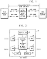
- the compression negotiation phase at bind time in an SNA communications environment is necessary to establish the duration or time span that a given compression will be employed between appropriate nodes on the path existing between the link termini. The outcome of a bind negotiation that might typically exist is shown in Figure 1.
- node or station 1 is designated, in accordance with SNA architectural principles, as the primary logical unit, or PLU. This is the initiator of a given session and would ordinarily be understood to be a terminal desiring to send a data message to a given target or node which would be the secondary logical unit, SLU, representing, for the purposes of this session definition, the other link terminal node.
- a communications link will thus exist over a pathway existing from node 1, the PLU, to node 3, the SLU, and encompassing, perhaps, intervening or intermediate nodes 2 such as shown in Figure 1.
- Each node will have its own inherent or native data compression capability depending upon the type of node or station that it is and how it has been configured.
- the compression capabilities could range from zero, or no capability upwards to SCB (string control byte) capability, to string control byte with small table Lempel-Ziv algorithmic capability (abbreviated ST) which includes SCB capability, and, finally, to large table Lempel-Ziv algorithm compression capability (abbreviated as LT) which is deemed to be capable of handling both small table Lempel-Ziv algorithm (ST) and SCB compression as well.
- SCB string control byte
- ST small table Lempel-Ziv algorithmic capability
- LT large table Lempel-Ziv algorithm compression capability
- Sublinks for the overall route or path represented from the link termini PLU1 and SLU3 in Figure 1, exist between stations 1 and 2 and 2 and 3, 3 and 2 and 2 and 1, each sublink comprising two nodes.
- Various degrees of compression may be practiced by communicating pairs of nodes as is evident.
- node 1 could communicate using SCB compression to node 2 which, due to its higher capability, is capable of handling compressed communications from PLU node 1 or SLU node 3.
- node 2 has a higher capability of compression that it may utilize with node 3 which has the capability to accept data so compressed from node 2.
- link terminal node 1 of Figure 1 which is to initiate a communication session with the target link terminal node 3.
- These nodes are designated in SNA parlance as the "primary logical unit” (PLU) and the "secondary logical unit” (SLU) between whom requests for session initiation and responses flow.
- Intervening node 2 is not a link terminal nodes since the link being established is between node 1 and node 3. Node 2 is, however, an intervening or intermediate node that may participate in data compression or decompression if that is advantageous.
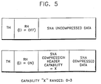
- a message is initiated by link terminal node 1 in a format such as that shown in Figure 5 for SNA message communication with a compression indicator capable of showing compression capabilities from 0 to 3, with a "1" indicating that it has the capability, for example as shown in Figure 1, to conduct SCB compression as its highest degree of capability.
- Message M2 is thus transmitted from node 1 downstream, or in a "first" direction, to the next adjacent node.
- the message M2 will be addressed, of course, to the intended target node 3, but it will be received enroute as message M1 by the intervening node 2 where the compression control indicator in the SNA header of Figure 5 will be observed and compared with the capability for compression which is supported by node 2.
- a message M2 will be generated and sent by each node such as by node 2 downstream as a new "M2" message toward the target node 3.
- the message M2 will contain an indicator for the greatest degree of compression represented either by that capability exhibited by node 2 or that which it received in the "M1" message sent as "M2" from the link terminal node 1.
- the highest degree of compression capability is communicated to the next adjacent downstream station by each station involved in the overall link between node 1 and node 3 in this example.
- the comparison is also made between the capability indicated as the highest degree supportable over the link between node 1 and node 3 and the capability of compression implemented at node 3.
- a return message M4 is generated and sent back upstream where it is received as M3 at node 2.
- M3 designates the upstream direction or a "second" direction opposite to that in which the initiation messages were propagated.
- M3 and M4 are thus, "response" messages.
- M3 contains an indicator for the compression capability which is the lesser of node 3's own capability or that which it received from the upstream direction. This process propagates back upstream to node 2 where a comparison is made between the compression degree indicator received from node 3 and that received from the upstream partner for node 2.
- node 2 is capable of handling communications from node 1 in the maximum degree of compression that node 1 is capable of supporting.
- node 1 will send an indicator showing a capability of "SCB" compression which will be received in message M1 by node 2.
- Node 2 has small table Lempel-Ziv compression capability (ST) and will indicate that capability via a new message M2 sent downstream to node 3.
- Node 3 is a link terminal and thus will not propagate messages further downstream in this session.
- Node 3 will compare its capability with the indication received as message M1 from upstream.
- node 3 also has ST capability.
- the rule of comparison is that node terminal link 3 should send the lower capability of either its own or that which it received. In this case, the capabilities are equal, so an indicating message is sent back upstream indicating ST capability.
- node 2 which also has ST compression capability, the message is compared to the capability received from its upstream partner, namely node 1, which indicated SCB capability.
- the lesser capability of that which was received from downstream and that which was received from upstream is transmitted back upstream to node 1.
- node 1 will receive an indication that SCB compression may be supported over the link to its neighbor node 2 downstream.
- Node 1 will set its mode control logic to compress and decompress utilizing SCB compression on all transmissions and receptions which it receives from or transmits to the link.
- Node 2 will set its mode of operation for "M1" reception from the upstream node, node 1, to SCB compression decoding or decompression, but will set its mode of communication "M2" with the downstream node or nodes as ST compression since it has learned that ST compression can be supported over the link between it and the target node 3. If another intervening node (not shown) were to exist having no compression capability, it would, nevertheless, have compared its capability against that received from upstream and from downstream and would have adopted a mode of raw or "no" compression or decompression, i.e. "straight transmission" for communications destined through it.
- a node should not participate in any compression or decompression unless some advantageous result such as a higher degree of compression over a sublink (such as between node 2 and node 3 or node 3 and node 2) might be obtained.
- Node 3 having received from upstream a message "M1" indicating that ST compression capability exists over its receiving side link, adopts a mode for decompression and compression of ST rather than the lesser degree of compression of which it is capable, i.e. SCB compression.
- the intermediate nodes should drop out of doing any compression or decompression since the left and right partners of such nodes can handle one another's compression and decompression without the help or aid of the intermediate node.
- each node must include, at a minimum, a register for storing a compression capability indicator pertinent to that node's inherent highest capability and other registers to store the indicators which it may receive from upstream or downstream partners.
- a comparator circuit and a mode control circuit are also required as is evident from the foregoing discussion. All of these elements are shown schematically in Figure 3 and in more detail in Figure 4 as noted above.
- the overall node logical elements for compression capability indication and indication message generation are shown as follows.
- M1 is the received message sent as M2 by the next upstream node to the present node.
- M2 is thus the downstream propagated message from any node and is shown for node 2 as contained in a register for M2 designated register 6.
- upstream received messages are sent by any node as messages M4 from a register 7 and upstream bound messages are received incoming as messages M3 and stored in a register 8.
- the mode's own degree of compression capability is stored in a register 9 and control logic 10 interfaces to all of the registers 5 through 9 as well as the mode control registers 11 and 12 which indicate the degree of compression or decompression to be employed with messages received from left or right, i.e. upstream or downstream partners.
- control logic includes message generation and mode control mechanisms that most appropriately are implemented in a program process to be performed by a microprocessor or the like, but which may be equally well implemented in program logic arrays or hard logic.
- the control logic 10 is only schematically indicated in Figure 3 as details of implementation will be apparent from the process flows which will be given later and the more detailed schematic implementation to be given.
- messages received at a node as coming from upstream are designated M1 but they are sent by the upstream node as a downstream message M2.
- upstream messages are sent as messages M4 and are received at a receiver node as incoming upstream messages M3.
- the M designations are arbitrary and are used for convenience in generating the logical tables for selecting the mode control and for determining what message should be generated and sent.
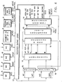
- FIG 4 the detailed logic contained in each node for doing the compression capability comparisons and controlling the mode setting operation and for generating the messages M2 or M4 to be communicated upstream and downstream are shown as follows:
- the registers 5 through 12 from Figure 3 are shown at the top of Figure 4.
- Register gating logic 13 under control of the processor logic 10 and control register 14 are shown.
- Incoming messages M1 and M3 are shown by arrows directed to the registers 5 and 8 while outbound messages are shown by the arrows directed outward from registers 7 and 6.
- the gating logic 13 is controlled by gating signals from control register 14 as set by mode selection logic from the processor 10 to control gating of the contents of register 9 into register 7 or the contents of register 8 into register 7 after logical comparisons have been made.
- Control register 14 also supplies mode control gating signals to the left and right mode control registers 11 and 12 respectively.
- the possible settings for the mode control registers 11 and 12 include 0 for no compression, 1 for SCB compression, 2 for small table Lempel-Ziv and 3 for large table Lempel-Ziv in this example.
- Logic also controls whether the values 0 through 3 loaded into the registers 11 and 12 come from the values represented in M1 or M3 or from the node's own register 9 for both the left and right mode control registers 11 and 12 in accordance with logical rules of decision that will be discussed in greater detail later.
- the control register 14 also provides gating selection signals to the selectors 15 and 16 to select input from register gating logic 13 as either M1 or M3 into selector 15 or M3 or the highest compression capability value into selector 16.
- the outputs of the selectors 15 and 16 are controlled into the comparator 17 by control signals from the processor logic 10 where comparisons are made between M1, M3 and the highest node compression capability value which the node has.
- the output of the comparator 17 indicates whether the comparison between the selected inputs finds them equal to each other, one greater than the other or one less than the other as indicated by the three output lines from comparator 17 to the mode register selector 18.
- Mode register selector 18 supplies the selection signals under control of the logic unit 10 as shown by the control line connecting the made register selector 18 with the input selector gates 15 and 16. The results of the chosen comparison of inputs is provided to the logic or processor unit 10 from the selector 18. In processor 10 the logical sequence of choices is made depending upon rules that will be described and a final mode selection and control setting signals are fed to the control register 14 and to the mode in gating controls as shown.
- the control processor 10 may operate a controlling program to enable it to perform the compression negotiation routine and mode setting functions. Simple logical tests are performed and then, based upon the outcome, the processor controls the gating of appropriate signals to the input or output registers and control registers.
- the small signals shown as "M1RDY” and “M3RDY” as inputs to the register selector 18 indicate that message M1 or M3 has arrived at the inputs and is ready for selection and comparison.
- the processor 10 first selects M1 inputs for comparison and then M3, awaiting the actual receipt of the messages prior to processing their contents. The processor will reset the selections once M3 and M1 registers have been gated to the selections determined by the processor and set into the control register 14.
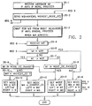
- the process begins in box 20-1 upon the receipt of an incoming M2 message from upstream at a given node. This will be received and is indicated as the receive message "M1".
- a comparison is performed between the incoming M1 and the node's own highest compression capability from register 9 as shown in box 20-2 and, as also shown in box 20-2, the downstream message M2 is generated, set into the M2 register 6 and sent as M2 downstream.
- the rule of generation employed in the comparison is that M2 will represent the highest capability represented either by the receive message M1 or that possessed by the node in its register 9.
- the message M2 will be a message such as shown in Figure 5 in which the SNA compression header has a capability indicator set to a value in the range of from 0 to 3 in the present example.
- the range of compression capabilities ranges from none which is indicated by a 0 to a high of 3 for a large table Limpel-Ziv compression algorithm, but it will be understood that such a designation is arbitrary and is illustrative only of the preferred embodiment.
- the processor enters a wait mode after sending message M2 when it waits for the arrival of message M3 from its right or downstream neighbor as shown in box 20-3.
- M3 is received and stored in a message register 8. If no message M3 is received or if, indeed, there is no right neighbor and the present node is the terminal link node, the flow proceeds with the assumption that message M3 was received with a value the same as M2 and the further processing tests are performed.
- Box 20-4 shows the receipt in register 8 of the upstream message M3 from the downstream or right neighbor.
- box 20-5 A comparison is made is box 20-5 between the incoming upstream message M1 and that received downstream to determine if they are equal and if the answer is "yes", the flow continues as shown to box 20-6 where message M4 is generated with a value equal to that found in message M3 and is propagated upstream while the modes of operation are set into register 11 and 12 with a value of 0, i.e. no compression or decompression to be conducted in this instance.
- test in box 20-5 indicates that M1 and M3 do not contain equal values
- the flow proceeds to box 20-7 where the comparison question is asked whether M1 is greater than M3.
- one of the output legs to box-8 or 20-9 is taken where further comparisons are conducted as shown which will lead either to additional comparison in 20-10 or the setting of the mode and message control registers in boxes 20-11, 12 or 13 as indicated by the flow arrows.
- any node failing to receive a message M3 will substitute in the comparison against its own capability the value which it would have generated for sending downstream, i.e. it loops the incoming message M1 to the M3 input in a logically equivalent manner.
- the specific communication technique practiced over the network of nodes is not a limiting or pertinent factor in the present invention.
- the invention concerns itself with the overall system of data communication utilizing the highest degree of supportable compression and with methods for negotiating what that degree of compression should be over each link and sublink.
- nodes having a higher degree of capability are sublinks in an overall link between a target and an initiating node, they may nevertheless participate in their own inherently higher capability with one another, provided only that they are capable of supporting lesser degrees of compression with neighbors.
- the most desirable network compression techniques employed will be those which are at least "upwardly compatible". This is meant to state that each station having a higher degree of compression capability should nevertheless, i.e. capable of handling communications at a lower degree of compression capability.
- Such hierarchically related compression capabilities have been demonstrated in the preferred embodiment, but numerous other selections of compression capability are capable of achieving the same hierarchical compatibility as will be apparent to those of skill in the art.
Landscapes
- Engineering & Computer Science (AREA)
- Computer Security & Cryptography (AREA)
- Computer Networks & Wireless Communication (AREA)
- Signal Processing (AREA)
- Compression, Expansion, Code Conversion, And Decoders (AREA)
- Communication Control (AREA)
- Data Exchanges In Wide-Area Networks (AREA)
- Small-Scale Networks (AREA)
Applications Claiming Priority (2)
| Application Number | Priority Date | Filing Date | Title |
|---|---|---|---|
| US638928 | 1991-01-09 | ||
| US07/638,928 US5131016A (en) | 1991-01-09 | 1991-01-09 | Communications network data compression control system and method |
Publications (2)
| Publication Number | Publication Date |
|---|---|
| EP0494576A1 true EP0494576A1 (de) | 1992-07-15 |
| EP0494576B1 EP0494576B1 (de) | 1996-10-02 |
Family
ID=24562025
Family Applications (1)
| Application Number | Title | Priority Date | Filing Date |
|---|---|---|---|
| EP91480191A Expired - Lifetime EP0494576B1 (de) | 1991-01-09 | 1991-12-20 | Verfahren und Vorrichtung zur Kontrolle des Kompressionsgrades, angewendet von einem Knoten eines Datenkommunikationsnetzwerkes |
Country Status (4)
| Country | Link |
|---|---|
| US (1) | US5131016A (de) |
| EP (1) | EP0494576B1 (de) |
| JP (1) | JP2522870B2 (de) |
| DE (1) | DE69122487D1 (de) |
Cited By (12)
| Publication number | Priority date | Publication date | Assignee | Title |
|---|---|---|---|---|
| GB2271253A (en) * | 1992-10-03 | 1994-04-06 | Ibm | Data compression at a video conference computer workstation |
| GB2271252A (en) * | 1992-10-03 | 1994-04-06 | Ibm | Data compression in a computer workstation |
| EP0860966A3 (de) * | 1997-02-20 | 1998-11-18 | Kabushiki Kaisha Toshiba | Verteiltes Netzwerkrechnersystem und Datenaustauschgerät |
| EP0883270A1 (de) * | 1997-06-03 | 1998-12-09 | Kabushiki Kaisha Toshiba | Verteiltes Netzwerkrechnersystem |
| WO2001001633A1 (en) * | 1999-06-29 | 2001-01-04 | Nokia Corporation | Apparatus and method for selectably operating radio device in alternate operating mode |
| WO2001005176A1 (en) * | 1999-07-14 | 2001-01-18 | Qualcomm Incorporated | Independant synchronisation of ppp links on um and rm interfaces |
| WO2001005177A1 (en) * | 1999-07-14 | 2001-01-18 | Qualcomm Incorporated | SELECTIVELY FRAMING AND UNFRAMING PPP PACKETS DEPENDING ON NEGOTIATED OPTIONS ON THE Um AND Rm INTERFACES |
| EP0975117A3 (de) * | 1998-07-17 | 2003-07-16 | Siemens Information and Communication Networks Inc. | System und Verfahren zur Optimierung der Übertragungssignalqualität |
| US6697336B1 (en) * | 1998-10-30 | 2004-02-24 | Telefonaktiebolaget Lm Ericsson (Publ) | Method to configure a communication link for a data transmission |
| US6721555B1 (en) * | 1999-02-19 | 2004-04-13 | Qualcomm Incorporated | System and method for facilitating device authentication in a wireless communications system |
| WO2005076569A1 (en) * | 2004-01-30 | 2005-08-18 | Nokia Corporation | Method and system for multiplexing of compressed control and user-plane messages |
| WO2006019380A1 (en) * | 2004-07-19 | 2006-02-23 | Thomson Licensing S.A. | Non-similar video codecs in video conferencing system |
Families Citing this family (27)
| Publication number | Priority date | Publication date | Assignee | Title |
|---|---|---|---|---|
| FR2670973B1 (fr) * | 1990-12-19 | 1994-04-15 | Ouest Standard Telematique Sa | Systeme de transmission par paquets a compression de donnees, procede et equipement correspondant. |
| US5392344A (en) * | 1991-10-03 | 1995-02-21 | At&T Corp. | Communications network class-of-service routing |
| US5524110A (en) * | 1993-11-24 | 1996-06-04 | Intel Corporation | Conferencing over multiple transports |
| US5574934A (en) * | 1993-11-24 | 1996-11-12 | Intel Corporation | Preemptive priority-based transmission of signals using virtual channels |
| CA2145921A1 (en) * | 1994-05-10 | 1995-11-11 | Vijay Pochampalli Kumar | Method and apparatus for executing a distributed algorithm or service on a simple network management protocol based computer network |
| CA2186795A1 (en) * | 1995-11-17 | 1997-05-18 | Cormac John Sreenan | Resource management system for a broadband multipoint bridge |
| US5850526A (en) * | 1996-02-07 | 1998-12-15 | Kingston Technology Co. | LAN station for determining the destination LAN station is capable of decompressing by comparing destination address to block of addresses assigned by a LAN manufacturer |
| US7543018B2 (en) * | 1996-04-11 | 2009-06-02 | Aol Llc, A Delaware Limited Liability Company | Caching signatures |
| US6112250A (en) * | 1996-04-11 | 2000-08-29 | America Online, Inc. | Recompression of files at an intermediate node in a network system |
| GB9621243D0 (en) * | 1996-10-11 | 1996-11-27 | Nokia Mobile Phones Ltd | Dect/gcm interworking |
| JP3834897B2 (ja) * | 1996-11-26 | 2006-10-18 | ソニー株式会社 | 情報信号伝送装置 |
| US6115394A (en) * | 1998-03-04 | 2000-09-05 | Ericsson Inc. | Methods, apparatus and computer program products for packet transport over wireless communication links |
| US5956490A (en) * | 1998-06-30 | 1999-09-21 | Motorola, Inc. | Method, client device, server and computer readable medium for specifying and negotiating compression of uniform resource identifiers |
| EP1411700B8 (de) * | 1999-08-06 | 2006-08-30 | Matsushita Electric Industrial Co., Ltd. | Datenübertragungsverfahren, -vorrichtung und Datenempfangsvorrichtung |
| US6826153B1 (en) | 2000-09-13 | 2004-11-30 | Jeffrey Kroon | System and method of increasing the message throughput in a radio network |
| US6816458B1 (en) * | 2000-09-13 | 2004-11-09 | Harris Corporation | System and method prioritizing message packets for transmission |
| US6826152B1 (en) * | 2000-09-13 | 2004-11-30 | Harris Corporation | System and method of conserving bandwidth in the transmission of message packets |
| US6801571B1 (en) * | 2000-10-11 | 2004-10-05 | Motorola, Inc. | Method and apparatus for optimizing data compression in a wireless digital access system |
| US7382730B2 (en) * | 2000-11-16 | 2008-06-03 | Cisco Technology, Inc. | Two-pass method and apparatus for achieving maximal data compression for a modem relay mode of operation in a voice frame network |
| SE0004736D0 (sv) * | 2000-12-20 | 2000-12-20 | Ericsson Telefon Ab L M | Mapping system and method |
| US7010727B1 (en) * | 2001-06-15 | 2006-03-07 | Nortel Networks Limited | Method and system for negotiating compression techniques to be utilized in packet data communications |
| TWI250724B (en) * | 2002-10-11 | 2006-03-01 | Ericsson Telefon Ab L M | Method and communication system for packeting messaging, and header compressor unit |
| US7324533B1 (en) | 2003-02-25 | 2008-01-29 | Cisco Technology, Inc. | Using modem profiles to improve connectivity, connect timing, and compression performance on a modem relay (MR) gateway |
| SE0402396D0 (sv) * | 2004-10-05 | 2004-10-05 | Ericsson Telefon Ab L M | Refresh of cached terminal capabilities data |
| US7885294B2 (en) * | 2007-08-23 | 2011-02-08 | Cisco Technology, Inc. | Signaling compression information using routing protocols |
| EP2209265B1 (de) * | 2007-10-31 | 2015-08-26 | Fujitsu Limited | Kommunikationsverfahren und kommunikationsendgerät, datentransfereinrichtung und steuerung |
| KR101500677B1 (ko) * | 2014-01-13 | 2015-03-18 | 이화여자대학교 산학협력단 | 선택적 데이터 압축 알고리즘을 사용하는 애드혹 네트워크 시스템 및 애드혹 네트워크에서 데이터를 전송하는 방법 |
Citations (3)
| Publication number | Priority date | Publication date | Assignee | Title |
|---|---|---|---|---|
| US4058672A (en) * | 1976-11-10 | 1977-11-15 | International Telephone And Telegraph Corporation | Packet-switched data communications system |
| WO1984000266A1 (en) * | 1982-06-25 | 1984-01-19 | Western Electric Co | End-to-end information memory arrangement in a line controller |
| EP0332345A2 (de) * | 1988-03-11 | 1989-09-13 | AT&T Corp. | Kodizes mit Unterdrückung von mehreren Codierungen/Decodierungen über eine Verbindung |
Family Cites Families (4)
| Publication number | Priority date | Publication date | Assignee | Title |
|---|---|---|---|---|
| US4679187A (en) * | 1985-04-22 | 1987-07-07 | International Business Machines Corp. | Adaptive trunk-compression system with constant grade of service |
| JP2713883B2 (ja) * | 1986-02-07 | 1998-02-16 | 株式会社日立製作所 | 時分割交換機 |
| US4890282A (en) * | 1988-03-08 | 1989-12-26 | Network Equipment Technologies, Inc. | Mixed mode compression for data transmission |
| US4899147A (en) * | 1988-06-03 | 1990-02-06 | Unisys Corporation | Data compression/decompression apparatus with throttle, start-up and backward read controls |
-
1991
- 1991-01-09 US US07/638,928 patent/US5131016A/en not_active Expired - Fee Related
- 1991-10-14 JP JP3265096A patent/JP2522870B2/ja not_active Expired - Fee Related
- 1991-12-20 DE DE69122487T patent/DE69122487D1/de not_active Expired - Lifetime
- 1991-12-20 EP EP91480191A patent/EP0494576B1/de not_active Expired - Lifetime
Patent Citations (3)
| Publication number | Priority date | Publication date | Assignee | Title |
|---|---|---|---|---|
| US4058672A (en) * | 1976-11-10 | 1977-11-15 | International Telephone And Telegraph Corporation | Packet-switched data communications system |
| WO1984000266A1 (en) * | 1982-06-25 | 1984-01-19 | Western Electric Co | End-to-end information memory arrangement in a line controller |
| EP0332345A2 (de) * | 1988-03-11 | 1989-09-13 | AT&T Corp. | Kodizes mit Unterdrückung von mehreren Codierungen/Decodierungen über eine Verbindung |
Cited By (17)
| Publication number | Priority date | Publication date | Assignee | Title |
|---|---|---|---|---|
| GB2271252A (en) * | 1992-10-03 | 1994-04-06 | Ibm | Data compression in a computer workstation |
| GB2271253A (en) * | 1992-10-03 | 1994-04-06 | Ibm | Data compression at a video conference computer workstation |
| EP0860966A3 (de) * | 1997-02-20 | 1998-11-18 | Kabushiki Kaisha Toshiba | Verteiltes Netzwerkrechnersystem und Datenaustauschgerät |
| US5966451A (en) * | 1997-02-20 | 1999-10-12 | Kabushiki Kaisha Toshiba | Distributed network computing system, and data exchange apparatus and method and storage medium used in this system |
| EP0883270A1 (de) * | 1997-06-03 | 1998-12-09 | Kabushiki Kaisha Toshiba | Verteiltes Netzwerkrechnersystem |
| EP0975117A3 (de) * | 1998-07-17 | 2003-07-16 | Siemens Information and Communication Networks Inc. | System und Verfahren zur Optimierung der Übertragungssignalqualität |
| US6697336B1 (en) * | 1998-10-30 | 2004-02-24 | Telefonaktiebolaget Lm Ericsson (Publ) | Method to configure a communication link for a data transmission |
| US6721555B1 (en) * | 1999-02-19 | 2004-04-13 | Qualcomm Incorporated | System and method for facilitating device authentication in a wireless communications system |
| US6477156B1 (en) | 1999-06-29 | 2002-11-05 | Nokia Corporation | Apparatus, and associated method, for selectably operating radio device in alternate operating mode |
| WO2001001633A1 (en) * | 1999-06-29 | 2001-01-04 | Nokia Corporation | Apparatus and method for selectably operating radio device in alternate operating mode |
| WO2001005177A1 (en) * | 1999-07-14 | 2001-01-18 | Qualcomm Incorporated | SELECTIVELY FRAMING AND UNFRAMING PPP PACKETS DEPENDING ON NEGOTIATED OPTIONS ON THE Um AND Rm INTERFACES |
| US6377556B1 (en) | 1999-07-14 | 2002-04-23 | Qualcomm Incorporated | Method and apparatus to resynchronize ppp on um interface without affecting ppp on a rm interface and to resynchronize ppp on a rm interface without affecting ppp on a um interface |
| WO2001005176A1 (en) * | 1999-07-14 | 2001-01-18 | Qualcomm Incorporated | Independant synchronisation of ppp links on um and rm interfaces |
| US6625164B1 (en) | 1999-07-14 | 2003-09-23 | Qualcomm, Incorporated | Selectively framing and unframing PPP packets depending on negotiated options on the Um and Rm interfaces |
| WO2005076569A1 (en) * | 2004-01-30 | 2005-08-18 | Nokia Corporation | Method and system for multiplexing of compressed control and user-plane messages |
| US7627692B2 (en) | 2004-01-30 | 2009-12-01 | Nokia Corporation | Multiplexing of compressed control and user-plane messages |
| WO2006019380A1 (en) * | 2004-07-19 | 2006-02-23 | Thomson Licensing S.A. | Non-similar video codecs in video conferencing system |
Also Published As
| Publication number | Publication date |
|---|---|
| JPH05160835A (ja) | 1993-06-25 |
| DE69122487D1 (de) | 1996-11-07 |
| EP0494576B1 (de) | 1996-10-02 |
| US5131016A (en) | 1992-07-14 |
| JP2522870B2 (ja) | 1996-08-07 |
Similar Documents
| Publication | Publication Date | Title |
|---|---|---|
| US5131016A (en) | Communications network data compression control system and method | |
| CA2035213C (en) | Modem having speed notifying means | |
| US5179555A (en) | High speed data compression and transmission for wide area network connections in LAN/bridging applications | |
| US4905282A (en) | Feature negotiation protocol and dynamically adjustable retraining sequence for a high speed half duplex modem | |
| US4953210A (en) | Feature negotiation protocol for a synchronous modem | |
| US9654419B2 (en) | Fabric channel control apparatus and method | |
| US7412245B2 (en) | Dynamic wireless meshing network for supporting load balance and flow control | |
| US20230085423A1 (en) | Packet communication system, and its transmitting apparatus, receiving apparatus, and program | |
| JPH05300145A (ja) | パス設定経路探索方法及びそれに用いる多重化装置 | |
| EP1673910B1 (de) | Inband-aushandlung in einzel-transkompressions-szenarien-verwandten anwendungen | |
| EP0333615B1 (de) | Verfahren zur Feststellung der Gruppennummer für eine Netztrecke | |
| WO1992004790A1 (en) | High speed data compression and transmission for wide area network connections in lan/bridging applications | |
| JPH05260120A (ja) | 非同期型時分割多重方式による伝送リンク上で可変長データブロックにより通信情報を伝送する方法及びシステム | |
| EP1249984A2 (de) | Kommunikationsdurchgangssystem | |
| JP2001320439A (ja) | ファイル転送方法、及びそのシステム | |
| US6778555B1 (en) | Voice over packet system configured to connect different facsimile transmission protocols | |
| CN114302449B (zh) | 信息传输方法及装置 | |
| US7573836B2 (en) | Switch system and loop transfer method | |
| JP3227857B2 (ja) | データ伝送方式 | |
| JP2924449B2 (ja) | リンク選択方式 | |
| JPH11196128A (ja) | 通信ネットワークシステム、及びそれに用いられる受信確認方法 | |
| Cosell et al. | Telnet issues | |
| JP2000049836A (ja) | リング状ネットワークのデータ伝送システム | |
| JP2003234778A (ja) | パケット交換原理によるデータ通信システム | |
| JP2529862B2 (ja) | 多線条リング形ネットワ−ク |
Legal Events
| Date | Code | Title | Description |
|---|---|---|---|
| PUAI | Public reference made under article 153(3) epc to a published international application that has entered the european phase |
Free format text: ORIGINAL CODE: 0009012 |
|
| AK | Designated contracting states |
Kind code of ref document: A1 Designated state(s): DE FR GB |
|
| 17P | Request for examination filed |
Effective date: 19921119 |
|
| 17Q | First examination report despatched |
Effective date: 19950207 |
|
| GRAG | Despatch of communication of intention to grant |
Free format text: ORIGINAL CODE: EPIDOS AGRA |
|
| GRAH | Despatch of communication of intention to grant a patent |
Free format text: ORIGINAL CODE: EPIDOS IGRA |
|
| GRAH | Despatch of communication of intention to grant a patent |
Free format text: ORIGINAL CODE: EPIDOS IGRA |
|
| GRAA | (expected) grant |
Free format text: ORIGINAL CODE: 0009210 |
|
| AK | Designated contracting states |
Kind code of ref document: B1 Designated state(s): DE FR GB |
|
| REF | Corresponds to: |
Ref document number: 69122487 Country of ref document: DE Date of ref document: 19961107 |
|
| PG25 | Lapsed in a contracting state [announced via postgrant information from national office to epo] |
Ref country code: DE Effective date: 19970103 |
|
| ET | Fr: translation filed | ||
| PLBE | No opposition filed within time limit |
Free format text: ORIGINAL CODE: 0009261 |
|
| STAA | Information on the status of an ep patent application or granted ep patent |
Free format text: STATUS: NO OPPOSITION FILED WITHIN TIME LIMIT |
|
| 26N | No opposition filed | ||
| PGFP | Annual fee paid to national office [announced via postgrant information from national office to epo] |
Ref country code: FR Payment date: 20011218 Year of fee payment: 11 |
|
| REG | Reference to a national code |
Ref country code: GB Ref legal event code: IF02 |
|
| PGFP | Annual fee paid to national office [announced via postgrant information from national office to epo] |
Ref country code: GB Payment date: 20021202 Year of fee payment: 12 |
|
| PG25 | Lapsed in a contracting state [announced via postgrant information from national office to epo] |
Ref country code: FR Free format text: LAPSE BECAUSE OF NON-PAYMENT OF DUE FEES Effective date: 20030901 |
|
| REG | Reference to a national code |
Ref country code: FR Ref legal event code: ST |
|
| PG25 | Lapsed in a contracting state [announced via postgrant information from national office to epo] |
Ref country code: GB Free format text: LAPSE BECAUSE OF NON-PAYMENT OF DUE FEES Effective date: 20031220 |
|
| GBPC | Gb: european patent ceased through non-payment of renewal fee |
Effective date: 20031220 |