EP0495511B1 - Drahtschneidefunkenerosionsmaschine - Google Patents
Drahtschneidefunkenerosionsmaschine Download PDFInfo
- Publication number
- EP0495511B1 EP0495511B1 EP92100740A EP92100740A EP0495511B1 EP 0495511 B1 EP0495511 B1 EP 0495511B1 EP 92100740 A EP92100740 A EP 92100740A EP 92100740 A EP92100740 A EP 92100740A EP 0495511 B1 EP0495511 B1 EP 0495511B1
- Authority
- EP
- European Patent Office
- Prior art keywords
- wire electrode
- speed
- tension
- output
- comparison result
- Prior art date
- Legal status (The legal status is an assumption and is not a legal conclusion. Google has not performed a legal analysis and makes no representation as to the accuracy of the status listed.)
- Expired - Lifetime
Links
Images


Classifications
-
- B—PERFORMING OPERATIONS; TRANSPORTING
- B23—MACHINE TOOLS; METAL-WORKING NOT OTHERWISE PROVIDED FOR
- B23H—WORKING OF METAL BY THE ACTION OF A HIGH CONCENTRATION OF ELECTRIC CURRENT ON A WORKPIECE USING AN ELECTRODE WHICH TAKES THE PLACE OF A TOOL; SUCH WORKING COMBINED WITH OTHER FORMS OF WORKING OF METAL
- B23H7/00—Processes or apparatus applicable to both electrical discharge machining and electrochemical machining
- B23H7/02—Wire-cutting
- B23H7/08—Wire electrodes
- B23H7/10—Supporting, winding or electrical connection of wire-electrode
-
- B—PERFORMING OPERATIONS; TRANSPORTING
- B23—MACHINE TOOLS; METAL-WORKING NOT OTHERWISE PROVIDED FOR
- B23H—WORKING OF METAL BY THE ACTION OF A HIGH CONCENTRATION OF ELECTRIC CURRENT ON A WORKPIECE USING AN ELECTRODE WHICH TAKES THE PLACE OF A TOOL; SUCH WORKING COMBINED WITH OTHER FORMS OF WORKING OF METAL
- B23H7/00—Processes or apparatus applicable to both electrical discharge machining and electrochemical machining
- B23H7/02—Wire-cutting
- B23H7/08—Wire electrodes
- B23H7/10—Supporting, winding or electrical connection of wire-electrode
- B23H7/104—Wire tension control
Definitions
- the present invention relates to a device for accurately controlling the tension of a wire electrode in a wirecut electrical discharge machine.
- Fig. 1 illustrates a wire electrode driving system (JP-A-3-264 213) for a conventional wirecut electrical discharge machine.
- the conventional wirecut electrical discharge machine includes numerous parts, namely, a workpiece 1, a wire electrode 2 for machining the workpiece 1, a wire bobbin 3 where the wire electrode 2 is spooled, a torque motor 4 attached to the shaft of the wire bobbin 3, brake rollers 5a and 5b for applying tension on the wire electrode 2, a brake motor 6 directly connected with the brake roller 5a, a tachometer 7 for detecting the speed of the brake motor 6, an upper pulley 8 for supporting the wire electrode 2 above the workpiece 1 and changing the running direction thereof, a lower pulley 9 for supporting the wire electrode 2 under the workpiece 1 and changing the running direction thereof, wire electrode recovery rollers 10a and 10b for driving the wire electrode 2, a constant-speed motor 11 directly connected with the wire electrode pinch roller 10a, an NC unit 12 for providing tension and running speed command values for the wire electrode 2, a comparator
- the wire electrode 2 which is spooled off the wire bobbin 3, is fed through a gap between the pair of brake rollers 5a and 5b where tension is applied.
- the running direction of the wire electrode 2 is then changed by the upper pulley 8 which is located above the workpiece 1.
- the wire electrode 2 is supplied to a machining area where the workpiece 1 can be machined.
- the running direction is again changed by the lower pulley 9 placed under the workpiece 1.
- the wire electrode 2 is wound around the pair of recovery rollers 10a and 10b which act to pull the wire electrode 2 through the machine.
- the wire bobbin 3 is driven by the torque motor 4 to apply tension of about 200 grams to the wire electrode 2 so that the wire electrode 2 does not slack between the wire bobbin 3 and the brake rollers 5a and 5b.
- the brake roller 5a is furnished with the brake motor 6 to tension the wire electrode 2 in the machine.
- the brake roller 5a is coupled to the brake motor 6 which controls the torque with which the brake roller 5a moves in accordance with the tension command value provided by the NC unit 12.
- the speed of the wire electrode 2 through the brake rollers 5a and 5b is detected as a voltage by the tachometer 7 installed on the brake motor 6.
- the voltage detected by the tachometer 7 includes an alternating-current (AC) component and a direct-current (DC) component.
- the output of the tachometer 7 is compared by the comparator 13 with the speed command value for the wire electrode 2 given by the NC unit 12, provided that the output of the tachometer 7 is compensated by the amplifier 14 in order to match the characteristic of the particular tachometer 7 output with that of the running speed command value provided by the NC unit 12.
- the output of the comparator 13 and the tension command value provided by the NC unit 12 are operated on by the compensator 15.
- the pinch roller 10a is coupled to the constant-speed motor 11.
- the speed of the constant-speed motor 11 determines the running speed of the wire electrode 2 through the machine in accordance with the running speed command value provided by the NC unit 12.
- the conventional wirecut electrical discharge machine is configured to keep the tension of the wire electrode 2 stable relative to dynamically varying tension (an AC component).
- the dynamically varying tension is, for example, a tension variation caused by the natural frequency of the wire system due to a disturbance, such as a machining counterforce.
- the tension variation causes the wire recovery speed through the pinch roller 10a and take up roller 10b to be higher than the speed of the wire electrode 2 through the brake rollers 5a and 5b
- the tension of the wire electrode 2 increases. Consequently, the comparator 13 outputs a positive signal, and the compensator 15 functions to reduce the tension.
- the tension variation causes the recovery speed of the wire electrode 2 at the pinch roller 10a and take up roller 10b to be lower than the speed of the wire electrode 2 at the brake rollers 5a and 5b
- the tension of the wire electrode system is decreased and the comparator 13 gives a negative signal so that the compensator 15 operates to raise the tension.
- the dynamically varying tension is controlled to be constant.
- the tension of the wire electrode 2 changes if a difference is produced between the running speed of the wire electrode 2 through the brake rollers 5a and 5b and the speed command value from the NC unit 12.
- the conventional machine cannot completely eliminate statically varying tension (the DC component) which occurs when the wire electrode stretches.
- the DC component the DC component which occurs when the wire electrode stretches.
- the wire electrode 2 stretches, causing the running speed of the wire electrode 2 at the brake rollers 5a and 5b to be lower than that at the pinch roller 10a and take up roller 10b.
- the DC component of a voltage difference equivalent to the running speed difference is generated in the comparator 13.
- the compensator 15 undesirably operates to reduce the tension in accordance with the DC component.
- the generated voltage characteristic is not proportionate to the tachometer speed, a difference occurs between the voltage provided by the tachometer and the speed command value for the wire electrode, which changes the tension of the wire electrode. Further, if the tachometer output characteristic is not matched extremely accurately with the running speed command value, a DC component of the voltage difference is produced in the comparator 13 and changes the set tension of the wire electrode 2, leading to difficulty in the adjustment of the amplifier.
- the running performance of the wire electrode 2 employed for machining the workpiece in the wirecut electrical discharge machine has great influence on machining accuracy, and in particular, the tension of the wire electrode 2 is an essential factor in determining the running performance.
- the tension of the wire electrode is ordinarily set to a slightly higher value, to the extent that the wire electrode will not be broken. Therefore, if the tension of the wire electrode running system falls below the set value, problems will arise, e.g., the desired machining accuracy cannot be achieved. Conversely, if the tension of the wire electrode running system rises above the set value, the wire electrode will be broken or other problems may occur.
- Another conventional wirecut electrical discharge apparatus (FR-A-24 27 870) comprises control means supplying control commands to pulling means and to tensioning means, respectively.
- the tensioning means as well as the pulling means are provided with speed sensors for detecting the speed of the wire electrode upstream and downstream of a machining area.
- the output signals of the speed sensors are compared in a logic unit the output of which representing the tension of the wire electrode are supplied to the control means for actualizing the control commands output from the control means.
- a further conventional wirecut electrical discharge apparatus includes detecting means for detecting the initial tension of a wire electrode. The detected initial tension is compared with a corresponding command value. The result of this comparison is used for controlling the initial tension break in order to cause both values to accord with each other.
- the object of the present invention is to provide a wirecut electrical discharge machine which allows the tension of a wire electrode to be kept constant dynamically as well as statically. Further, it is an object of the present invention to provide a method for controlling tension of a wire electrode in a wirecut electrical discharge apparatus.
- Accurate control of the tension of a wire electrode in a wirecut electrical discharge machine can be achieved by eliminating a direct current component of a speed difference signal between a breaking section and a recovery section of the machine.
- the direct current component of the speed signal which is eliminated is associated with the stretching of the wire electrode while under tension.
- the tension can be maintained constant by compensating the tension command signal in response to an alternating current component of the speed signal.
- Fig. 2 illustrates a wirecut electrical discharge machine according to a first embodiment of the present invention.
- the elements of the wirecut electrical discharge machine are shown, namely, a workpiece 1, a wire electrode 2 for machining the workpiece 1, a wire bobbin 3 around which the wire electrode 2 is spooled, a torque motor 4 mounted on the shaft of the wire bobbin 3, brake rollers 5a and 5b for applying tension on the wire electrode 2, a brake motor 6 directly connected with the brake roller 5a, a tachometer 7 for detecting the speed of the brake motor 6, an upper pulley 8 for supporting the wire electrode 2 above the workpiece 1 and changing the running direction thereof, a lower pulley 9 for supporting the wire electrode 2 under the workpiece 1 and changing the running direction thereof, wire electrode pinch roller 10a and take up roller 10b for running the wire electrode 2, a constant-speed motor 11 directly connected with the wire electrode pinch roller 10a, a numerical control unit 12 (hereinafter "NC unit") for providing tension and running speed command values for the wire
- the wire electrode 2 which is spooled off the wire bobbin 3, passes between the pair of brake rollers 5a and 5b where tension is applied.
- the brake rollers 5a and 5b together with the brake motor 6 form a braking section of the machine.
- the braking section applies tension to the wire electrode 2.
- the running direction of the wire electrode 2 is then changed by the upper pulley 8 which is placed above the workpiece 1.
- the wire electrode 2 is supplied to a machining area where the workpiece 1 can be machined.
- the running direction is again changed by the lower pulley 9 placed under the workpiece 1.
- the wire electrode 2 is wound around the pair of pinch roller 10a and take up roller 10b which act to pull the wire electrode 2 through the machine.
- the pinch roller 10a and take up roller 10b together with the constant-speed motor 11 form a wire receiving section.
- the wire bobbin 3 is coupled to the torque motor 4 to apply tension of approximately 200 grams on the wire electrode 2 so that the wire electrode 2 does not slack between the wire bobbin 3 and the brake rollers 5a and 5b.
- the brake roller 5a is coupled to the brake motor 6 to apply tension to the wire electrode 2 in the machine.
- the brake motor 6 controls the torque with which the brake roller 5a moves in accordance with the tension command value provided by the NC unit 12.
- the pinch roller 10a is coupled to the constant-speed motor 11.
- the speed of the constant-speed motor 11 determines the running speed of the wire electrode 2 through the machine in accordance with the running speed command value provided by the NC unit 12, e.g., a voltage level applied to the constant-speed motor 11.
- the speed of the wire electrode 2 through the braking section is detected as a voltage by the tachometer 7 which is coupled to the brake motor 6.
- the output of the tachometer 7, which includes AC and DC components, is compared by the comparator 13 with the running speed command value of the wire electrode 2 provided by the NC unit 12.
- the output of the comparator 13 passes through the filter 16 where its DC component is removed.
- the compensator 15 then compensates the tension command value for the wire electrode 2 in accordance with the output of the filter 16.
- the dynamically varying tension can thereafter be controlled in a conventional manner.
- the error of the speed difference signal of the comparator 13 produced statically is removed by the filter 16.
- the filter 16 For example, when tension is applied on the wire electrode 2, the wire electrode 2 stretches, causing a difference between the running speed of the wire electrode 2 in the braking section and that of the wire electrode 2 in the wire recovery section, and then generating the DC component of a voltage equivalent to the difference in the comparator 13.
- the set tension of the wire electrode 2 remains unchanged.
- the set tension of the wire electrode 2 remains the same if there is a difference between the output characteristic of the tachometer 7 and the running speed command value for the wire electrode 2.
- the amplifier 14 can also be easily adjusted such that it matches the characteristics of the running speed command value provided by the NC unit 12.
- Fig. 3 illustrates an embodiment of the filter 16.
- the filter 16 illustrated in Fig. 3 is a high-pass filter which includes a resistor 20, a capacitor 21, and an operational amplifier 22.
- Fig. 4 is a diagram illustrating a second embodiment of the present invention.
- the second embodiment operates the same as the first embodiment except that the speed of the wire electrode 2 through the wire recovery section is detected directly with a tachometer 17.
- the tachometer 17 is mounted on the shaft end of the constant-speed motor 11. Further, the speed of the wire electrode 2 detected by the tachometer 17 is used in the comparator 13 instead of the running speed command value from the NC unit 12.
- the filter 16 is not limited to the high-pass filter illustrated in Fig. 3, but may be any device that reduces gain in the low-frequency range, e.g., a phase lead compensating circuit or a band-pass filter.
- the brake motor 6 of the braking section which is utilized to apply tension may be a DC motor, an AC motor or other braking device.
- the tachometer 7 employed for detecting the speed of the wire electrode 2 through the braking section may be replaced by an encoder and the output of the encoder may be converted from a frequency to a voltage, thus producing a similar effect.
- the speed of the wire electrode 2 in the braking section is detected through the direct connection of the brake roller 5a and the brake motor 6, the speed of the wire electrode 2 may be detected by any other method if that speed is detected in the vicinity of the braking section.
- Fig. 5 is a diagram of a wirecut electrical discharge machine according to a third embodiment of the present invention.
- an integrator 16' and a comparator 17 are provided instead of the filter 16 which appears in the first embodiment.
- the integrator 16' integrates the output of the comparator 13 and feeds back the result to the comparator 17.
- the comparator 17 compares the output of the tachometer 7 with the output from the integrator 16', and outputs a difference signal which is supplied to the comparator 13 through the amplifier 14.
- Fig. 6 is a graph illustrating operation of the integrator 16' of the third embodiment.
- Fig. 6 illustrates the operation of the integrator 16' and shows a voltage waveform at point P in Fig. 5.
- a time period marked A in Fig. 6 indicates a voltage waveform where there is no integrator 16', and a time period marked B indicates a voltage waveform where the integrator 16' has been inserted.
- the comparator 17 and the integrator 16' operate to provide negative feedback which removes the DC component from the output of the tachometer, so that the set tension of the wire electrode 2 remains unchanged.
- Fig. 7 is a graph illustrating a relationship between a tension command value and the tension of the wire electrode.
- the continuous line shown in Fig. 7 indicates an ideal curve and the broken line indicates a curve achieved by the conventional machine.
- the output of the comparator 13 i.e., the speed difference signal
- the output of the comparator 13 is output without a DC component after a length of time equivalent to the time constant T of the integrator 16' has elapsed (see region B in Fig. 6).
- primary control is unaffected by setting the time constant to a much longer value than the cycle of the speed difference signal. Namely, in the graph shown in Fig. 7, the tension coincides with the ideal curve even when the tension command value for the wire electrode is increased.
- the output signal of the integrator 16' can be fed back at the output of the NC unit 12, instead of at the output of tachometer 7, to produce the same effect.
- the second embodiment illustrated in Fig. 4 can be used to modify the third embodiment just as it does the first embodiment.
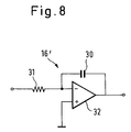
- Fig. 8 illustrates an embodiment of the integrator 16'.
- the integrator 16' illustrated in Fig. 8 is a an integrator circuit which includes a capacitor 30, a resistor 31, and an operational amplifier 32.
- integrator 16' and the filter 16 which operate to remove the direct current component from the speed difference signal are shown as analog circuits in Figs. 3 and 8, such analog circuits can be replaced by digital software processing using a digital processor (e.g., microprocessor) to produce the same effect.
- a digital processor e.g., microprocessor
Landscapes
- Chemical & Material Sciences (AREA)
- Chemical Kinetics & Catalysis (AREA)
- Electrochemistry (AREA)
- Engineering & Computer Science (AREA)
- Mechanical Engineering (AREA)
- Electrical Discharge Machining, Electrochemical Machining, And Combined Machining (AREA)
Claims (11)
- Elektrische Drahtschnittentladungsvorrichtung, umfassend:
eine Steuereinrichtung (12) zum Liefern eines Spannungsbefehls und eines Drahtgeschwindigkeitsbefehls;
eine Spannungsanlegungseinrichtung (5a, 5b) zum Anlegen einer Spannung an eine Drahtelektrode (2) entsprechend dem Spannungsbefehl von der Steuereinrichtung (12);
eine erste Geschwindigkeitserfassungseinrichtung (7) zum Erfassen einer Geschwindigkeit der Drahtelektrode (2) an der Spannungs-Anlegungseinrichtung (5a, 5b);
eine erste Vergleichseinrichtung (13) zum Vergleichen eines Werts anzeigend die Drahtelektrodengeschwindigkeit an einer stromabwärts gelegenen Posistion, die sich stromabwärts eines Arbeitsbereichs befindet, mit einem Wert auf Grundlage des Ausgangs der ersten Geschwindigkeitserfassungseinrichtung (7);
gekennzeichnet durch
eine Entfernungseinrichtung (16; 16', 17) zum Entfernen einer Gleichstromkomponente des Ausgangs der ersten Vergleichseinrichtung (13) zur Erzeugung eines ersten Vergleichsergebnisses; und
eine Kompensationseinrichtung (15) zum Kompensieren des Spannungsbefehls von der Steuereinrichtung (12) für die Spannungsanlegungseinrichtung (5a, 5b) auf Grundlage einer Wechselstromkomponente des ersten Vergleichsergebnisses. - Vorrichtung nach Anspruch 1, dadurch
gekennzeichnet, daß
der Drahtelektroden-Geschwindigkeitsbefehl von der Steuereinrichtung (12) an die erste Vergleichseinrichtung (13) als der Wert stellvertretend für die Drahtelektrodengeschwindigkeit an der stromabwärts gelegenen Position angelegt wird. - Vorrichtung nach Anspruch 1, dadurch
gekennzeichnet, daß
eine Zieheinrichtung (10a, 10b) zum Ziehen der Drahtelektrode (2) auf Grundlage des Drahtelektrodenbefehls von der Steuereinrichtung (12) und eine zweite Geschwindigkeitserfassungseinrichtung (27) zum Erfassen einer Geschwindigkeit der Drahtelektrode (2) an der Zieheinrichtung (10a, 10b) vorgesehen sind; und daß der Ausgang der zweiten Geschwindigkeitserfassungseinrichtung (27) an die Vergleichseinrichtung (13) als der Wert stellvertretend für die Drahtelektrodengeschwindigkeit an der stromabwärts gelegenen Position angelegt wird. - Vorrichtung nach Anspruch 1, 2 oder 3, dadurch
gekennzeichnet, daß
die Entfernungseinrichtung ein Hochpassfilter (16) umfaßt, dessen Ausgang an die Kompensationseinrichtung (15) angelegt ist. - Vorrichtung nach Anspruch 1, 2 oder 3, dadurch
gekennzeichnet, daß
die Entfernungseinrichtung umfaßt: eine Integrationseinrichtung (16') zum Integrieren des ersten Vergleichsergebnisses, das von der ersten Vergleichseinrichtung (13) ausgegeben wird, und eine zweite Vergleichseinrichtung (17) zum Vergleichen des Ausgangs der ersten Geschwindigkeitserfassungseinrichtung (7) mit dem Ausgang der Integrationseinrichtung (16');
wobei die erste Vergleichseinrichtung (13) einen Wert auf Grundlage des Ausgangs der zweiten Vergleichseinrichtung (17) mit einem Signal stellvertretend für die Drahtelektrodengeschwindigkeit an der stromabwärts gelegenen Position vergleicht. - Verfahren zum Steuern der Spannung einer Drahtelektrode in einer elektrischen Drahtschnittentladungsvorrichtung, wobei das Verfahren die folgenden Schritte umfaßt:(a) Empfangen eines Spannungs-Befehls und eines Drahtelektrodengeschwindigkeits-Befehls;(b) Anlegen einer Spannung an eine Drahtelektrode (2) auf Grundlage des Spannungs-Befehls;(c) Bestimmen der Geschwindigkeit der Drahtelektrode (2) an einer stromaufwärts gelegenen Position, die stromaufwärts von einem Arbeitsbereich liegt; und(d) Vergleichen der im Schritt (c) bestimmten Geschwindigkeit der Drahtelektrode (2) mit einem Wert stellvertretend für die Geschwindigkeit der Drahtelektrode an einer stromabwärts gelegenen Position, die stromabwärts eines Arbeitsbereichs liegt, um ein erstes Vergleichsergebnis zu erzeugen;gekennzeichnet durch
den folgenden Schritt:(e) Kompensieren des im Schritt (b) verwendeten Spannungs-Befehls auf Grundlage einer Wechselstromkomponente des ersten Vergleichsergebnisses. - Verfahren nach Anspruch 6, dadurch
gekennzeichnet, daß
der Drahtgeschwindigkeitsbefehl im Schritt (d) als der Wert stellvertretend für die Geschwindigkeit der Drahtelektrode an der stromabwärts gelegenen Position verwendet wird. - Verfahren nach Anspruch 6, dadurch
gekennzeichnet, daß
die Elektrode gemäß dem Drahtelektroden-Geschwindigkeitsbefehl gezogen wird; daß die Geschwindigkeit der Drahtelektrode an der stromabwärts gelegenen Position, die sich stromabwärts des Arbeitsbereichs befindet, bestimmt wird; und daß die Geschwindigkeit der Drahtelektrode an der stromaufwärts gelegenen Position im Schritt (d) mit der Geschwindigkeit der Drahtelektrode an der stromabwärts gelegenen Position verglichen wird. - Verfahren nach Anspruch 6, 7 oder 8, dadurch
gekennzeichnet, daß
der Kompensationsschritt die folgenden Schritte umfaßt:(e1) Entfernen einer Gleichstromkomponente des ersten Vergleichsergebnisses zur Erzeugung eines angepaßten Vergleichsergebnisses; und(e2) Kompensieren des Spannungs-Befehls auf Grundlage des angepaßten Vergleichsergebnisses. - Verfahren nach Anspruch 9, dadurch
gekennzeichnet, daß
der Entfernungsschritt (e1) den folgenden Schritt umfaßt: Herausfiltern der Gleichstromkomponente aus dem ersten Vergleichsergebnis und beibehalten der Wechselstromkomponente als das angepaßte Vergleichsergebnis. - Verfahren nach Anspruch 9, dadurch
gekennzeichnet, daß
der Entfernungsschritt (e1) den Schritt eines Integrierens des ersten Vergleichsergebnisses umfaßt.
Applications Claiming Priority (2)
| Application Number | Priority Date | Filing Date | Title |
|---|---|---|---|
| JP3003637A JP2692386B2 (ja) | 1991-01-17 | 1991-01-17 | ワイヤ放電加工装置 |
| JP3637/91 | 1991-01-17 |
Publications (3)
| Publication Number | Publication Date |
|---|---|
| EP0495511A2 EP0495511A2 (de) | 1992-07-22 |
| EP0495511A3 EP0495511A3 (en) | 1993-01-27 |
| EP0495511B1 true EP0495511B1 (de) | 1995-09-06 |
Family
ID=11563000
Family Applications (1)
| Application Number | Title | Priority Date | Filing Date |
|---|---|---|---|
| EP92100740A Expired - Lifetime EP0495511B1 (de) | 1991-01-17 | 1992-01-17 | Drahtschneidefunkenerosionsmaschine |
Country Status (5)
| Country | Link |
|---|---|
| US (1) | US5216217A (de) |
| EP (1) | EP0495511B1 (de) |
| JP (1) | JP2692386B2 (de) |
| KR (1) | KR940003943B1 (de) |
| DE (1) | DE69204475T2 (de) |
Families Citing this family (16)
| Publication number | Priority date | Publication date | Assignee | Title |
|---|---|---|---|---|
| US5856695A (en) * | 1991-10-30 | 1999-01-05 | Harris Corporation | BiCMOS devices |
| WO1998039128A1 (fr) * | 1997-03-07 | 1998-09-11 | Sodick Co., Ltd. | Systeme et procede d'usinage par decharge pour le decoupage par fil-electrode |
| JP3883690B2 (ja) * | 1998-03-04 | 2007-02-21 | 株式会社ソディック | ワイヤ放電加工機のワイヤ電極張力制御装置及びその方法並びに張力制御回路のフィルタの決定及び調整設定方法 |
| JP2007111777A (ja) * | 2005-10-18 | 2007-05-10 | Matsushita Electric Ind Co Ltd | サーボシステム |
| JP4168076B2 (ja) * | 2007-03-08 | 2008-10-22 | ファナック株式会社 | ワイヤ電極張力制御機能を有するワイヤカット放電加工機 |
| JP5241916B2 (ja) * | 2009-04-07 | 2013-07-17 | 三菱電機株式会社 | ワイヤ放電加工機のワイヤ走行系保全システム |
| JP5088975B2 (ja) * | 2010-10-19 | 2012-12-05 | 株式会社ソディック | ワイヤ放電加工装置 |
| JP5220179B2 (ja) * | 2011-12-09 | 2013-06-26 | 株式会社ソディック | ワイヤ放電加工機 |
| US20150290733A1 (en) * | 2012-10-30 | 2015-10-15 | Mitsubishi Electric Corporation | Wire electrical discharge machining apparatus, machining control device, and machining control program |
| CN104339046A (zh) * | 2014-10-28 | 2015-02-11 | 苏州市宝玛数控设备有限公司 | 一种运丝稳定的电火花线切割机构 |
| CN104339053A (zh) * | 2014-10-28 | 2015-02-11 | 苏州市宝玛数控设备有限公司 | 一种电极丝恒张力走丝机构 |
| CN104308304A (zh) * | 2014-10-28 | 2015-01-28 | 苏州市宝玛数控设备有限公司 | 一种电火花线切割机床走丝机构 |
| JP6133917B2 (ja) * | 2015-03-06 | 2017-05-24 | ファナック株式会社 | 張力の検出値を補正する機能を有するワイヤ放電加工機 |
| EP3290370B1 (de) * | 2016-08-31 | 2019-01-30 | Aumann Espelkamp GmbH | Drahtlaufvorrichtung |
| WO2018092181A1 (ja) * | 2016-11-15 | 2018-05-24 | 三菱電機株式会社 | ワイヤ放電加工機 |
| RS67252B1 (sr) | 2019-05-20 | 2025-10-31 | Schleuniger Ag | Postupak za kočenje najmanje jednog obrtnog valjka uređaja za ispravljanje, mašine za obradu kablova sa uređajem za ispravljanje |
Family Cites Families (10)
| Publication number | Priority date | Publication date | Assignee | Title |
|---|---|---|---|---|
| US3781490A (en) * | 1973-06-01 | 1973-12-25 | Ibm | Web tension and speed control in a reel-to-reel web transport |
| US4298781A (en) * | 1978-06-08 | 1981-11-03 | Inoue-Japax Research Incorporated | Wire-cut electroerosion machine and method of operating same |
| JPS59149259A (ja) * | 1983-02-08 | 1984-08-27 | Norihisa Sakabe | ウエブ巻戻し装置における起動時ウエブ張力の自動制御方法 |
| JPS61226468A (ja) * | 1985-04-01 | 1986-10-08 | Hitachi Ltd | 線巻き装置 |
| JPS63256316A (ja) * | 1987-04-13 | 1988-10-24 | Mitsubishi Electric Corp | ワイヤ放電加工装置 |
| JPH01199726A (ja) * | 1988-02-03 | 1989-08-11 | Fanuc Ltd | ワイヤ張力,断線検出制御装置 |
| JP2578357B2 (ja) * | 1988-05-27 | 1997-02-05 | 三菱電機株式会社 | 放電加工制御装置 |
| JPH0241826A (ja) * | 1988-07-28 | 1990-02-13 | Fanuc Ltd | ワイヤ張力制御方式 |
| JPH02152726A (ja) * | 1988-12-02 | 1990-06-12 | Mitsubishi Electric Corp | ワイヤ放電加工機のワイヤ供給装置 |
| JP2571711B2 (ja) * | 1989-01-10 | 1997-01-16 | 三菱電機株式会社 | ワイヤ放電加工機のワイヤ供給装置 |
-
1991
- 1991-01-17 JP JP3003637A patent/JP2692386B2/ja not_active Expired - Fee Related
- 1991-09-03 KR KR1019910015339A patent/KR940003943B1/ko not_active Expired - Fee Related
-
1992
- 1992-01-17 EP EP92100740A patent/EP0495511B1/de not_active Expired - Lifetime
- 1992-01-17 US US07/821,808 patent/US5216217A/en not_active Expired - Lifetime
- 1992-01-17 DE DE69204475T patent/DE69204475T2/de not_active Expired - Lifetime
Also Published As
| Publication number | Publication date |
|---|---|
| EP0495511A3 (en) | 1993-01-27 |
| DE69204475D1 (de) | 1995-10-12 |
| JP2692386B2 (ja) | 1997-12-17 |
| KR940003943B1 (ko) | 1994-05-09 |
| DE69204475T2 (de) | 1996-03-14 |
| US5216217A (en) | 1993-06-01 |
| KR920014551A (ko) | 1992-08-25 |
| EP0495511A2 (de) | 1992-07-22 |
| JPH04261716A (ja) | 1992-09-17 |
Similar Documents
| Publication | Publication Date | Title |
|---|---|---|
| EP0495511B1 (de) | Drahtschneidefunkenerosionsmaschine | |
| US4982816A (en) | Speed control system for elevators | |
| US5166490A (en) | Wire cut electric discharge machining apparatus | |
| US4760233A (en) | Drilling confirming apparatus of electric discharge machining system | |
| US4864091A (en) | Servocontrol device for an erosion machine | |
| JP2003266247A (ja) | ワイヤ放電加工機のワイヤ張力制御装置 | |
| EP0667203A1 (de) | System zur drahtspannungssteuerung | |
| EP0335599A2 (de) | Geschwindigkeitsregelgerät mit einem Umrichter | |
| EP0602490A2 (de) | Verfahren und Vorrichtung zur Schlupfkompensation einer Induktionsmaschine | |
| JP2723451B2 (ja) | ワイヤ放電加工装置 | |
| JPH01121128A (ja) | ワイヤ放電加工装置 | |
| JP2935583B2 (ja) | エレベータ用インバータの速度制御装置 | |
| SU821245A1 (ru) | Способ управлени тиристорнымРЕгул ТОРОМ TOKA ВОзбуждЕНи СЕРиЕС-НОгО Т гОВОгО дВигАТЕл | |
| JPH0593389A (ja) | 抄紙機用電動機の制御装置 | |
| SU1395579A1 (ru) | Устройство дл регулировани нат жени длинномерного материала при перемотке | |
| KR100212495B1 (ko) | 권선기 장력제어 장치 | |
| JPH07118940A (ja) | 紡機におけるスライバ斑制御装置 | |
| JPH0725529A (ja) | 張力制御装置 | |
| JP2594968B2 (ja) | 誘導電動機の駆動制御装置 | |
| JPS6326272A (ja) | 非消耗電極式自動溶接におけるア−ク長制御方法およびその装置 | |
| JPS6156823A (ja) | 放電加工装置の電極送り制御方法 | |
| JPH0453787B2 (de) | ||
| KR0166915B1 (ko) | 모터의 속도 및 위상 제어장치 | |
| JP2002144153A (ja) | 放電加工装置 | |
| JPH1014281A (ja) | 電動機の制御装置 |
Legal Events
| Date | Code | Title | Description |
|---|---|---|---|
| PUAI | Public reference made under article 153(3) epc to a published international application that has entered the european phase |
Free format text: ORIGINAL CODE: 0009012 |
|
| AK | Designated contracting states |
Kind code of ref document: A2 Designated state(s): CH DE LI |
|
| PUAL | Search report despatched |
Free format text: ORIGINAL CODE: 0009013 |
|
| AK | Designated contracting states |
Kind code of ref document: A3 Designated state(s): CH DE LI |
|
| 17P | Request for examination filed |
Effective date: 19930225 |
|
| 17Q | First examination report despatched |
Effective date: 19940317 |
|
| GRAA | (expected) grant |
Free format text: ORIGINAL CODE: 0009210 |
|
| AK | Designated contracting states |
Kind code of ref document: B1 Designated state(s): CH DE LI |
|
| REF | Corresponds to: |
Ref document number: 69204475 Country of ref document: DE Date of ref document: 19951012 |
|
| PLBE | No opposition filed within time limit |
Free format text: ORIGINAL CODE: 0009261 |
|
| STAA | Information on the status of an ep patent application or granted ep patent |
Free format text: STATUS: NO OPPOSITION FILED WITHIN TIME LIMIT |
|
| 26N | No opposition filed | ||
| PGFP | Annual fee paid to national office [announced via postgrant information from national office to epo] |
Ref country code: CH Payment date: 20080116 Year of fee payment: 17 |
|
| REG | Reference to a national code |
Ref country code: CH Ref legal event code: PL |
|
| PG25 | Lapsed in a contracting state [announced via postgrant information from national office to epo] |
Ref country code: LI Free format text: LAPSE BECAUSE OF NON-PAYMENT OF DUE FEES Effective date: 20090131 Ref country code: CH Free format text: LAPSE BECAUSE OF NON-PAYMENT OF DUE FEES Effective date: 20090131 |
|
| PGFP | Annual fee paid to national office [announced via postgrant information from national office to epo] |
Ref country code: DE Payment date: 20110112 Year of fee payment: 20 |
|
| REG | Reference to a national code |
Ref country code: DE Ref legal event code: R071 Ref document number: 69204475 Country of ref document: DE |
|
| REG | Reference to a national code |
Ref country code: DE Ref legal event code: R071 Ref document number: 69204475 Country of ref document: DE |
|
| PG25 | Lapsed in a contracting state [announced via postgrant information from national office to epo] |
Ref country code: DE Free format text: LAPSE BECAUSE OF EXPIRATION OF PROTECTION Effective date: 20120118 |