EP0497380A2 - Mikrorechner mit Zeitüberwachungseinrichtung - Google Patents
Mikrorechner mit Zeitüberwachungseinrichtung Download PDFInfo
- Publication number
- EP0497380A2 EP0497380A2 EP92101729A EP92101729A EP0497380A2 EP 0497380 A2 EP0497380 A2 EP 0497380A2 EP 92101729 A EP92101729 A EP 92101729A EP 92101729 A EP92101729 A EP 92101729A EP 0497380 A2 EP0497380 A2 EP 0497380A2
- Authority
- EP
- European Patent Office
- Prior art keywords
- interrupt
- watchdog timer
- processing request
- wdt
- request
- Prior art date
- Legal status (The legal status is an assumption and is not a legal conclusion. Google has not performed a legal analysis and makes no representation as to the accuracy of the status listed.)
- Granted
Links
Images


Classifications
-
- G—PHYSICS
- G06—COMPUTING OR CALCULATING; COUNTING
- G06F—ELECTRIC DIGITAL DATA PROCESSING
- G06F11/00—Error detection; Error correction; Monitoring
- G06F11/07—Responding to the occurrence of a fault, e.g. fault tolerance
- G06F11/0703—Error or fault processing not based on redundancy, i.e. by taking additional measures to deal with the error or fault not making use of redundancy in operation, in hardware, or in data representation
- G06F11/0751—Error or fault detection not based on redundancy
- G06F11/0754—Error or fault detection not based on redundancy by exceeding limits
- G06F11/0757—Error or fault detection not based on redundancy by exceeding limits by exceeding a time limit, i.e. time-out, e.g. watchdogs
-
- G—PHYSICS
- G06—COMPUTING OR CALCULATING; COUNTING
- G06F—ELECTRIC DIGITAL DATA PROCESSING
- G06F11/00—Error detection; Error correction; Monitoring
- G06F11/07—Responding to the occurrence of a fault, e.g. fault tolerance
- G06F11/0703—Error or fault processing not based on redundancy, i.e. by taking additional measures to deal with the error or fault not making use of redundancy in operation, in hardware, or in data representation
- G06F11/0706—Error or fault processing not based on redundancy, i.e. by taking additional measures to deal with the error or fault not making use of redundancy in operation, in hardware, or in data representation the processing taking place on a specific hardware platform or in a specific software environment
- G06F11/0721—Error or fault processing not based on redundancy, i.e. by taking additional measures to deal with the error or fault not making use of redundancy in operation, in hardware, or in data representation the processing taking place on a specific hardware platform or in a specific software environment within a central processing unit [CPU]
-
- G—PHYSICS
- G06—COMPUTING OR CALCULATING; COUNTING
- G06F—ELECTRIC DIGITAL DATA PROCESSING
- G06F11/00—Error detection; Error correction; Monitoring
- G06F11/07—Responding to the occurrence of a fault, e.g. fault tolerance
- G06F11/0703—Error or fault processing not based on redundancy, i.e. by taking additional measures to deal with the error or fault not making use of redundancy in operation, in hardware, or in data representation
- G06F11/0793—Remedial or corrective actions
-
- G—PHYSICS
- G06—COMPUTING OR CALCULATING; COUNTING
- G06F—ELECTRIC DIGITAL DATA PROCESSING
- G06F13/00—Interconnection of, or transfer of information or other signals between, memories, input/output devices or central processing units
- G06F13/14—Handling requests for interconnection or transfer
- G06F13/20—Handling requests for interconnection or transfer for access to input/output bus
- G06F13/24—Handling requests for interconnection or transfer for access to input/output bus using interrupt
- G06F13/26—Handling requests for interconnection or transfer for access to input/output bus using interrupt with priority control
-
- Y—GENERAL TAGGING OF NEW TECHNOLOGICAL DEVELOPMENTS; GENERAL TAGGING OF CROSS-SECTIONAL TECHNOLOGIES SPANNING OVER SEVERAL SECTIONS OF THE IPC; TECHNICAL SUBJECTS COVERED BY FORMER USPC CROSS-REFERENCE ART COLLECTIONS [XRACs] AND DIGESTS
- Y02—TECHNOLOGIES OR APPLICATIONS FOR MITIGATION OR ADAPTATION AGAINST CLIMATE CHANGE
- Y02D—CLIMATE CHANGE MITIGATION TECHNOLOGIES IN INFORMATION AND COMMUNICATION TECHNOLOGIES [ICT], I.E. INFORMATION AND COMMUNICATION TECHNOLOGIES AIMING AT THE REDUCTION OF THEIR OWN ENERGY USE
- Y02D10/00—Energy efficient computing, e.g. low power processors, power management or thermal management
Definitions
- the present invention relates to a microcomputer, and more specifically to a microcomputer having a central processing unit, and a watchdog timer generating a non-maskable interrupt in response to an overflow of the timer.
- microcomputers including a central processing unit (often abbreviated to “CPU” in the specification), an interrupt controller (often abbreviated to “INTC” in the specification), and peripheral circuits such as an A/D converter and a serial transfer circuit, all of which are assembled in a single semiconductor substrate chip, comprise a watchdog timer (often abbreviated to "WDT” in the specification) generating a non-maskable interrupt in response to an overflow of the timer in order to elevate reliability of the whole of the microcomputer system.
- CPU central processing unit
- INTC interrupt controller
- peripheral circuits such as an A/D converter and a serial transfer circuit
- a program for clearing (or presetting) a counter of the watchdog timer within each predetermined time period without exception is prepared, so that if the program executed without trouble, no overflow of the watchdog timer is generated. For example, at a time of program runaway, if the counter of the watchdog timer is not preset because of occurrence of anomaly even after the predetermined time period has elapsed, an overflow occurs in the watchdog timer. This overflow is detected as a non-maskable interrupt, and an abnormality of the system is notified to an external device, and an operation is branched to a previously programmed routine such as a reset routine for performing a processing for the anomaly occurrence.
- the WDT (watchdog timer) interrupt cannot be masked by an EI flag or the like, differently from ordinary maskable interrupts. Therefore, when another interrupt processing routine is under execution, if the WDT interrupt occurs, the operation is branched to the WDT interrupt processing routine. Accordingly, when it is necessary to prepare a program which is generated and processed asynchronously from an execution condition of an internal program, similarly to an interrupt processing routine for processing an interrupt request from an external device, there is possibility that the counter of the watchdog timer cannot be preset within the predetermined time period. Therefore, in order to preventing the WDT interrupt from occurring because the situation is misunderstood as being the system abnormality, the WDT present instruction is executed at a beginning of the interrupt processing routine.
- the WDT present instruction is executed at a beginning of the interrupt processing routine.in order to prevent the time from being wasted because of the occurrence of the WDT interrupt.
- the CPU does not receive an interrupt request from the interrupt controller without exception just after the operation is branched to the interrupt processing routine. Namely, an instruction at a heading address of the interrupt processing routine is surely executed.
- the interrupt controller performs receipt of interrupt processing requests and a priority level control, and notifies occurrence of interrupt request to the CPU.
- this interrupt controller is configured to process a first occurred request and to retain late occurred request(s). Therefore, when an external terminal interrupt request occurs and is transferred from the interrupt controller to the CPU, if the WDT interrupt processing request occurs and is notified to the interrupt controller in a period in which the CPU is executing the branch processing going to the external terminal interrupt processing routine, the CPU first branches to the external terminal interrupt processing routine so as to execute the heading instruction thereof, and thereafter, branches to the WDT interrupt processing routine.
- the watchdog timer presetting is executed at the beginning of the interrupt processing routine, if the overflow occurs in the watchdog timer, it is in certain case that during the execution of the external terminal interrupt processing the operation is branched to the WDT interrupt processing routine by the WDT interrupt processing request notified to the CPU.
- Another object of the present invention is to provide a microcomputer having a watchdog timer and which does not branch to the WDT interrupt processing routine when the WDT interrupt request occurs in the course of execution of a first or previously branched interrupt processing routine.
- a microcomputer comprising a central processing unit, a watchdog timer generating a processing request when an overflow occurs in the watchdog timer, an interrupt control circuit processing as a non-maskable interrupt the processing request generated by the watch timer, means for outputting a preset signal to the watchdog timer in response to execution of an instruction of the central processing unit, so as to preset the watchdog timer, and means responding to the preset signal for cancelling the processing request generated by the watchdog timer during a period of time of retaining the processing request by the interrupt control circuit.
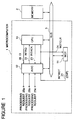
- FIG. 1 there is shown a block diagram of an essential part of one embodiment of the microcomputer in accordance with the present invention.
- the shown microcomputer is configured so that when a CPU (central processing unit) executes a WDT (watchdog timer) preset instruction, an interrupt controller (INTC) automatically cancel a WDT interrupt which has not yet been received by the CPU or is retained by the CPU.
- a CPU central processing unit
- WDT watchdog timer
- INTC interrupt controller
- the shown microcomputer is generally designated by Reference Numeral 1, and is coupled through a bus 5 to a memory unit 2.
- the microcomputer 1 includes therein a CPU 10, a watch timer 11 and an interrupt controller 12, which are coupled through the bus 5 for a mutual data transfer between the CPU 10, the watch timer 11 and the interrupt controller 12.
- the CPU 10 includes therein a program counter, a program status word, an arithmetic and logic unit, an instruction decoder, various control registers, maskable interrupt disable/enable flags etc., which are not shown in the drawing for simplification of the drawings since these elements are well known to persons skilled in the art.
- the CPU 10 performs various internal operation controls of the microcomputer 1 including control of execution of instructions including a preset instruction used only for the watchdog timer 11 and an interrupt processing control.
- the memory unit 2 includes a program memory and a data memory (both of which are not shown) for storing various types of data.
- the watchdog timer 11 is configured to start its count operation when the CPU 10 executes a WDT preset instruction after a resetting of the system and generates a WDTCLR (watchdog timer clear) signal 24. Thereafter, each time the WDT preset instruction is executed, the watchdog timer is preset. Here, the counting operation of the watchdog timer cannot be stopped by a method other than the inputting of system reset. If an overflow occurs in the watchdog timer before the WDT preset instruction is executed, the watchdog timer 11 generates a WDT interrupt processing request INTWDT 21, which is inputted to the interrupt controller 12.
- the interrupt controller 12 receives a maskable interrupt enable signal EI 26, and performs the receipt control and the priority level control of the processing request INTWDT 21 and other occurring interrupt requests, on the basis of the received maskable interrupt enable signal EI 26 and contents of internal control registers provided in the interrupt controller. As a result, when a condition for receiving the interrupt is satisfied, the interrupt controller 12 outputs an interrupt request signal INTREQ (INTRO) 22 to the CPU 10.
- INTRO interrupt request signal
- the CPU 10 receives the interrupt request signal INTREQ 22, the CPU stops a programmed processing being executed, and executes the interrupt processing. Namely, in order to be capable of restarting the stopped programmed processing, the CPU 10 saves information of the program counter and the program status word to a stack area of the memory unit 2. In addition, the CPU generates an interrupt acknowledge signal INTACK 23 to the interrupt controller 12, and receives through the bus 5 from the interrupt controller 12, vector information for the interrupt request having the highest priority level among the presently occurring interrupt requests. On the basis of the received vector information, the CPU 10 branches to a heading or beginning address of an interrupt processing routine previously set in the memory unit 2. Thereafter, the branched interrupt processing routine is executed.
- a return instruction IRET is executed, so that the program stopped because of the interrupt processing is restarted.
- the information of the program counter and the program status word saved in the stack area of the memory unit 2 is returned or restored.
- the WDTCLR signal 24 is supplied to not only the watchdog timer but also the interrupt controller 12, and in response to the WDTCLR signal 24, the interrupt controller 12 cancels the WDT interrupt request internally held in the interrupt controller 12.
- interrupt controller 12 will be described with reference to the logic circuit diagram of Figure 2 illustrating the internal structure of the interrupt controller 12.
- the interrupt processing requests controlled by the interrupt controller 12 are four, namely three ordinary interrupt processing requests 25a, 25b and 25c, and the WDT interrupt processing request INTWDT 21.
- the interrupt controller 12 includes four interrupt request flags 30a, 30b, 30c and 30d for individually storing a non-maskable interrupt processing request 25a, the WDT interrupt processing request INTWDT 21, and maskable interrupt processing requests 25b and 25c, respectively, and a mask flags 31b and 31c for individually disabling and enabling the maskable interrupt processing requests 25b and 25c, respectively.
- the interrupt controller 12 includes a priority level control unit 33 for performing a priority level control between the interrupt processing requests 25a, 25b and 25c and the WDT interrupt processing request INTWDT 21, so as to select an interrupt processing request having the highest priority level, and a vector generation unit 34 for generating a vector information corresponding to a selected one of the interrupt processing requests 25a, 25b and 25c and the WDT interrupt processing request INTWDT 21.
- the generated vector information is outputted to the bus 5 through a controlled buffer 35 which is activated when the interrupt request acknowledge signal 23 is active.
- the interrupt request flag 30a has a set input S connected to receive the interrupt processing request 25a, and a Q output connected to an input of a latch 331a of the priority level control unit 33.
- a selection signal 35a outputted from the latch 331a is connected to the vector generation unit 34 and one input of an AND gate 301a having an output connected to a reset input R of the flag 30a.
- the interrupt request flag 30d has a set input S connected to receive the interrupt processing request INTWDT 21, and a Q output connected to an input of a non-inverting input of an AND gate 332d of the priority level control unit 33.
- the AND gate 332d has an inverting input connected to the Q output of the flag 30a, and an output of the AND gate 332d is connected to an input of a latch 331d of the priority level control unit 33.
- a selection signal 35d outputted from the latch 331d is connected to the vector generation unit 34 and one input of an AND gate 301d having an output connected through an OR gate 302 to a reset input R of the flag 30d.
- the OR gate 302 receives the WDTCLR signal 24 at its other input.
- the interrupt request flag 30b has a set input S connected to receive the interrupt processing request 25b, and a Q output connected to an input of a non-inverting input of an AND gate 334b of the priority level control unit 33.
- the AND gate 334b has another non-inverting input connected to receive the EI signal 26 and an inverting input connected to the mask flag 31b.
- An output of the AND gate 334b is connected to a non-inverting input of an AND gate 332b.
- the AND gate 332b has an inverting input connected to an output of an OR gate 333d having a pair of inputs connected to the Q output of the flags 30a and 30d, respectively.
- An output of the AND gate 332b is connected to an input of a latch 331b of the priority level control unit 33.
- a selection signal 35b outputted from the latch 331b is connected to the vector generation unit 34 and one input of an AND gate 301b having an output connected to a reset input R of the flag 30b.
- the interrupt request flag 30c has a set input S connected to receive the interrupt processing request 25c, and a Q output connected to an input of a non-inverting input of an AND gate 334c of the priority level control unit 33.
- the AND gate 334c has another non-inverting input connected to receive the EI signal 26 and an inverting input connected to the mask flag 31c.
- An output of the AND gate 334c is connected to a non-inverting input of an AND gate 332c.
- the AND gate 332c has an inverting input connected to an output of an OR gate 333b having a pair of inputs connected to the output of the AND gate 334b and the output of the OR gate 333d, respectively.
- An output of the AND gate 332c is connected to an input of a latch 331c of the priority level control unit 33.
- a selection signal 35c outputted from the latch 331c is connected to the vector generation unit 34 and one input of an AND gate 301c having an output connected to a reset input R of the flag 30b.
- the output of the AND gate 334c and the output of the OR gate 333b are connected to a pair of inputs of an OR gate 333c, which in turn has an output generating the interrupt request signal INTRQ 22 to the CPU 10.
- the other input of each of the AND gates 301a, 301b, 301c and 301d is connected to receive the interrupt acknowledge signal 23.
- the internal latches 331a to 331d operate to latch their input not only when their input is activated to “1” but also when the WDTCLR signal 24 is activated to "1".
- the priority levels of the interrupt processing requests 25a, 25b and 25c and the WDT interrupt processing request INTWDT 21 are fixed. Namely, the order of the priority levels is (the interrupt processing request 25a) > (the WDT interrupt processing request INTWDT 21) > the interrupt processing request 25b) > (the interrupt processing request 25c).
- the maskable interrupt requests are in an acknowledge enable condition (namely, the EI signal 26 is active and the mask flags 31b and 31c are not set.).
- the interrupt acknowledge signal 23 is supplied to the interrupt controller 12.
- the active selection signal 35d is passed through its associated AND gate 301d and applied to the reset input R of the interrupt request flag 30d, so as to reset the Q output of the interrupt request flag 30d to "0".
- the vector generation unit 34 outputs a vector information corresponding to the interrupt request INTWDT 21, through the bus to the CPU, since the control buffer 35 is put in an activated condition by the interrupt acknowledge signal 23.
- the signal level of the selection signals 25a to 25d are ordinarily held in the internal latches 331a to 331d of the priority level control unit 33, after the interrupt request signal INTRQ 22 is generated until the interrupt acknowledge signal INTACK 24 is generated by the CPU 10. Therefore, the interrupt receiving processing for the interrupt processing request 25 is suspended or retained.
- the interrupt request flag 30c is set to "1", which is informed to the priority level control unit 33.
- the selection signal 35c is activated to "1" which is transferred to the vector generation unit 34 and toward the interrupt request flag 30c, and the interrupt request signal INTRQ 22 is outputted to the CPU 10.
- all the other selection signals 35a, 35b and 35d are inactive, namely, "0".
- the interrupt request flag 30d is set "1", which is informed to the priority order control unit 33.
- the priority level relation is (the WDT interrupt processing request INTWDT 21) > the interrupt processing request 25c), but since the interrupt request 22 has been informed to the CPU 10, the selection signals 35a to 35d are maintained by the internal latches 331a to 331d until the interrupt acknowledge signal 23 is supplied to the interrupt controller 12 after the interrupt request 22 was acknowledged. Namely, the selection signals 35a to 35d remain unchanged. Accordingly, the interrupt acknowledge processing for the interrupt processing request INTWDT 21 is retained.
- an operation of cancelling the WDT interrupt when the WDT preset instruction is executed is as follows:
- the CPU outputs the WDTCLR signal 24 to the interrupt controller 12, so that the interrupt request flag 35d is reset to "0".
- the internal latches 311a to 331d performs the latching operation again in response to the WDTCLR signal 24, so that the internal latches 311a to 331d are updated.
- the selection signal 35d is inactivated to "0", and therefore, the occurrence of the interrupt processing request INTWDT 21 is cancelled. Accordingly, the WDT interrupt processing is never executed by the CPU 10, and the receipt control and the priority level control for the interrupt processing requests 25a to 25c other than the interrupt processing request INTWDT 21 are performed.
- the above mentioned embodiment is configured that when the CPU executes the WDT preset instruction, the interrupt controller automatically cancels the WDT interrupt request. Therefore, when the WDT interrupt request occurs concurrently with another interrupt request, if the WCT present instruction is executed at a beginning of the previously branched interrupt processing routine, the operation is never branched to the WDT interrupt processing routine even if the overflow has already generated and the interrupt processing request has been informed.
- FIG. 3 there is shown a block diagram of an essential part of another embodiment of the microcomputer in accordance with the present invention.
- the second embodiment is different from the first embodiment only in the method in which the WDT preset instruction to be executed by the CPU and the WDTCLR signal are generated. Therefore, elements similar to those shown in Figure 1 are given the same Reference Numerals and explanation thereof will be omitted.
- a microcomputer 201 of the second embodiment is such that a CPU 110 writes a predetermined data into an internal control register 101 of an watchdog timer 111 by using a general instruction, and a content of the internal control register 101 is decoded by an internal decoder 112, which presets a watchdog timer counter 103.
- the decoder 112 also generates a WDTCLR signal 124.
- the watchdog timer counter 103 generates the WDT interrupt processing request INTWDT 121 when an overflow occurs in the watchdog timer counter 103.
- the CPU 110 is not required to have therein a circuit for executing an instruction for only the WDT preset instruction. Therefore, it is possible to control the watchdog timer 111 even by using the CPU of the microcomputer having an instruction set which does not include the instruction for only the WDT preset instruction. This is applicable to a custom LSI (microcomputer) in which a CPU block is made in common and a peripheral circuit including the watchdog timer is customized.
- LSI microcomputer
- the WDT interrupt request flag is located in the interrupt controller.
- a similar effect can be expected even if modification is made to the effect that a flag for storing a processing request is internally provided in the watchdog timer and an interrupt request signal held in the flag internally provided in the watchdog timer is transferred to the interrupt controller. This is called a so called level interrupt control.
- the microcomputer in accordance with the present invention is such that when the WDT interrupt request occurs in conflict with another interrupt request, if the WDT preset instruction is executed at a beginning of the previously branched interrupt processing routine, the operation is never branched to the WDT interrupt processing routine even if the overflow has already generated and the interrupt processing request has been informed.
- the interrupt processing routine of the external terminal interrupt can be completed with a minimum time.
Landscapes
- Engineering & Computer Science (AREA)
- Theoretical Computer Science (AREA)
- Physics & Mathematics (AREA)
- General Engineering & Computer Science (AREA)
- General Physics & Mathematics (AREA)
- Quality & Reliability (AREA)
- Microcomputers (AREA)
- Debugging And Monitoring (AREA)
Applications Claiming Priority (2)
| Application Number | Priority Date | Filing Date | Title |
|---|---|---|---|
| JP3011827A JP2867717B2 (ja) | 1991-02-01 | 1991-02-01 | マイクロコンピュータ |
| JP11827/91 | 1991-02-01 |
Publications (3)
| Publication Number | Publication Date |
|---|---|
| EP0497380A2 true EP0497380A2 (de) | 1992-08-05 |
| EP0497380A3 EP0497380A3 (en) | 1993-05-12 |
| EP0497380B1 EP0497380B1 (de) | 1997-05-02 |
Family
ID=11788600
Family Applications (1)
| Application Number | Title | Priority Date | Filing Date |
|---|---|---|---|
| EP92101729A Expired - Lifetime EP0497380B1 (de) | 1991-02-01 | 1992-02-03 | Mikrorechner mit Zeitüberwachungseinrichtung |
Country Status (4)
| Country | Link |
|---|---|
| US (1) | US5408643A (de) |
| EP (1) | EP0497380B1 (de) |
| JP (1) | JP2867717B2 (de) |
| DE (1) | DE69219372T2 (de) |
Cited By (4)
| Publication number | Priority date | Publication date | Assignee | Title |
|---|---|---|---|---|
| KR100286783B1 (ko) * | 1997-03-21 | 2001-04-16 | 다니구찌 이찌로오, 기타오카 다카시 | 마이크로컴퓨터 |
| WO2005022387A3 (en) * | 2003-08-27 | 2005-05-12 | Philips Intellectual Property | Circuit arrangement and method for supporting and monitoring a microcontroller |
| CN100397353C (zh) * | 2006-07-26 | 2008-06-25 | 华为技术有限公司 | 一种提高单板异常处理能力的系统和方法 |
| CN104899125A (zh) * | 2015-06-04 | 2015-09-09 | 杭州华三通信技术有限公司 | 一种单板系统的运行信息获取方法和装置 |
Families Citing this family (50)
| Publication number | Priority date | Publication date | Assignee | Title |
|---|---|---|---|---|
| JPH04306735A (ja) * | 1991-04-04 | 1992-10-29 | Toshiba Corp | 非同期割込み禁止機構 |
| JP2658697B2 (ja) * | 1991-12-11 | 1997-09-30 | 富士通株式会社 | ウォッチ・ドック・タイマ回路 |
| US5530872A (en) * | 1992-12-23 | 1996-06-25 | International Business Machines Corporation | Method and system for directing device driver to service multiple sequential interrupt requests generated by I/O device connected thereto |
| JPH08132992A (ja) * | 1994-11-10 | 1996-05-28 | Mitsubishi Electric Corp | 車載用制御装置 |
| US5541943A (en) * | 1994-12-02 | 1996-07-30 | At&T Corp. | Watchdog timer lock-up prevention circuit |
| US5528756A (en) * | 1995-01-30 | 1996-06-18 | Elsag International N.V. | Method and apparatus for performing supervisory functions in digital systems and obtaining diagnostics thereof |
| KR0177093B1 (ko) * | 1995-05-31 | 1999-05-15 | 윤종용 | Cpu 리셋회로 |
| JP3357514B2 (ja) * | 1995-09-20 | 2002-12-16 | シャープ株式会社 | 暴走検出復帰方式 |
| JPH09160807A (ja) * | 1995-12-06 | 1997-06-20 | Mitsuba Corp | マイクロプロセッサの誤動作検出方法 |
| US7266725B2 (en) | 2001-09-03 | 2007-09-04 | Pact Xpp Technologies Ag | Method for debugging reconfigurable architectures |
| DE19651075A1 (de) | 1996-12-09 | 1998-06-10 | Pact Inf Tech Gmbh | Einheit zur Verarbeitung von numerischen und logischen Operationen, zum Einsatz in Prozessoren (CPU's), Mehrrechnersystemen, Datenflußprozessoren (DFP's), digitalen Signal Prozessoren (DSP's) oder dergleichen |
| US5787290A (en) * | 1996-12-20 | 1998-07-28 | International Business Machines Corporation | Adapter with an onboard interrupt controller for controlling a computer system |
| DE19654595A1 (de) | 1996-12-20 | 1998-07-02 | Pact Inf Tech Gmbh | I0- und Speicherbussystem für DFPs sowie Bausteinen mit zwei- oder mehrdimensionaler programmierbaren Zellstrukturen |
| US5819095A (en) * | 1996-12-20 | 1998-10-06 | International Business Machines Corporation | Method and apparatus for allowing an interrupt controller on an adapter to control a computer system |
| ATE243390T1 (de) | 1996-12-27 | 2003-07-15 | Pact Inf Tech Gmbh | Verfahren zum selbständigen dynamischen umladen von datenflussprozessoren (dfps) sowie bausteinen mit zwei- oder mehrdimensionalen programmierbaren zellstrukturen (fpgas, dpgas, o.dgl.) |
| US6542998B1 (en) | 1997-02-08 | 2003-04-01 | Pact Gmbh | Method of self-synchronization of configurable elements of a programmable module |
| US6012154A (en) * | 1997-09-18 | 2000-01-04 | Intel Corporation | Method and apparatus for detecting and recovering from computer system malfunction |
| DE19861088A1 (de) | 1997-12-22 | 2000-02-10 | Pact Inf Tech Gmbh | Verfahren zur Reparatur von integrierten Schaltkreisen |
| US6393590B1 (en) * | 1998-12-22 | 2002-05-21 | Nortel Networks Limited | Method and apparatus for ensuring proper functionality of a shared memory, multiprocessor system |
| US7003660B2 (en) | 2000-06-13 | 2006-02-21 | Pact Xpp Technologies Ag | Pipeline configuration unit protocols and communication |
| DE10081643D2 (de) | 1999-06-10 | 2002-05-29 | Pact Inf Tech Gmbh | Sequenz-Partitionierung auf Zellstrukturen |
| US6496890B1 (en) | 1999-12-03 | 2002-12-17 | Michael Joseph Azevedo | Bus hang prevention and recovery for data communication systems employing a shared bus interface with multiple bus masters |
| DE10049440A1 (de) * | 2000-10-06 | 2002-04-11 | Daimler Chrysler Ag | Verfahren zum Betrieb eines von einem Prozessor gesteuerten Systems |
| US8058899B2 (en) | 2000-10-06 | 2011-11-15 | Martin Vorbach | Logic cell array and bus system |
| DE10049441B4 (de) * | 2000-10-06 | 2008-07-10 | Conti Temic Microelectronic Gmbh | Verfahren zum Betrieb eines von einem Prozessor gesteuerten Systems |
| US9037807B2 (en) | 2001-03-05 | 2015-05-19 | Pact Xpp Technologies Ag | Processor arrangement on a chip including data processing, memory, and interface elements |
| US7844796B2 (en) * | 2001-03-05 | 2010-11-30 | Martin Vorbach | Data processing device and method |
| US7444531B2 (en) | 2001-03-05 | 2008-10-28 | Pact Xpp Technologies Ag | Methods and devices for treating and processing data |
| US7996827B2 (en) * | 2001-08-16 | 2011-08-09 | Martin Vorbach | Method for the translation of programs for reconfigurable architectures |
| US7434191B2 (en) | 2001-09-03 | 2008-10-07 | Pact Xpp Technologies Ag | Router |
| US8686475B2 (en) | 2001-09-19 | 2014-04-01 | Pact Xpp Technologies Ag | Reconfigurable elements |
| AU2003208266A1 (en) | 2002-01-19 | 2003-07-30 | Pact Xpp Technologies Ag | Reconfigurable processor |
| EP1351145A1 (de) * | 2002-04-04 | 2003-10-08 | Hewlett-Packard Company | Rechnerfehlerbehebung und Notifizierungssystem |
| US20040015741A1 (en) * | 2002-07-17 | 2004-01-22 | Adc Telecommunications Israel Ltd. | Watchdog device operation |
| EP1383047A1 (de) * | 2002-07-18 | 2004-01-21 | Cp8 | Verfahren zur Sicherung der Ausführung eines Programms gegen Strahlungsangriffe oder ähnliches |
| AU2003286131A1 (en) | 2002-08-07 | 2004-03-19 | Pact Xpp Technologies Ag | Method and device for processing data |
| US20040034701A1 (en) * | 2002-08-14 | 2004-02-19 | Adc Dsl Systems, Inc. | Watchdog termination in a communication system |
| WO2004038599A1 (de) | 2002-09-06 | 2004-05-06 | Pact Xpp Technologies Ag | Rekonfigurierbare sequenzerstruktur |
| US20040098573A1 (en) * | 2002-11-18 | 2004-05-20 | Adc Telecommunication Israel Ltd. | Configurable initialization of hardware |
| US20040250178A1 (en) * | 2003-05-23 | 2004-12-09 | Munguia Peter R. | Secure watchdog timer |
| JP4700611B2 (ja) * | 2003-08-28 | 2011-06-15 | ペーアーツェーテー イクスペーペー テクノロジーズ アクチエンゲゼルシャフト | データ処理装置およびデータ処理方法 |
| CN100405307C (zh) * | 2005-02-01 | 2008-07-23 | 艾默生网络能源有限公司 | 看门狗控制方法 |
| FR2888370A1 (fr) * | 2005-07-05 | 2007-01-12 | St Microelectronics Sa | Protection de l'execution d'un programme |
| WO2007082730A1 (de) * | 2006-01-18 | 2007-07-26 | Pact Xpp Technologies Ag | Hardwaredefinitionsverfahren |
| FR2910144A1 (fr) * | 2006-12-18 | 2008-06-20 | St Microelectronics Sa | Procede et dispositif de detection errones au cours de l'execution d'un programme. |
| US7783872B2 (en) * | 2007-03-30 | 2010-08-24 | Dell Products, Lp | System and method to enable an event timer in a multiple event timer operating environment |
| US9053233B2 (en) | 2011-08-15 | 2015-06-09 | Freescale Semiconductor, Inc. | Method and device for controlling debug event resources |
| US9436627B2 (en) | 2011-08-25 | 2016-09-06 | International Business Machines Corporation | Detection of abnormal operation caused by interrupt processing |
| JP5910793B2 (ja) * | 2013-04-26 | 2016-04-27 | 株式会社オートネットワーク技術研究所 | フェイルセーフ回路 |
| GB201405323D0 (en) * | 2014-03-25 | 2014-05-07 | Imagination Tech Ltd | Prioritsing events to which a processor is to respond |
Family Cites Families (7)
| Publication number | Priority date | Publication date | Assignee | Title |
|---|---|---|---|---|
| JPH0656591B2 (ja) * | 1981-07-06 | 1994-07-27 | 株式会社日立製作所 | デ−タ編集処理装置 |
| JPS60263235A (ja) * | 1984-06-12 | 1985-12-26 | Omron Tateisi Electronics Co | マイクロコンピユ−タシステム |
| JPS6129239A (ja) * | 1984-07-19 | 1986-02-10 | Nec Corp | プロセツサ異常再開方式 |
| JPH0795291B2 (ja) * | 1986-01-13 | 1995-10-11 | 沖電気工業株式会社 | ウオツチドツグタイマ |
| US4726024A (en) * | 1986-03-31 | 1988-02-16 | Mieczyslaw Mirowski | Fail safe architecture for a computer system |
| JPS6355601A (ja) * | 1986-08-26 | 1988-03-10 | Matsushita Electric Works Ltd | ウオツチドツグタイマ回路 |
| US4956842A (en) * | 1988-11-16 | 1990-09-11 | Sundstrand Corporation | Diagnostic system for a watchdog timer |
-
1991
- 1991-02-01 JP JP3011827A patent/JP2867717B2/ja not_active Expired - Fee Related
-
1992
- 1992-02-03 US US07/830,421 patent/US5408643A/en not_active Expired - Lifetime
- 1992-02-03 DE DE69219372T patent/DE69219372T2/de not_active Expired - Fee Related
- 1992-02-03 EP EP92101729A patent/EP0497380B1/de not_active Expired - Lifetime
Non-Patent Citations (2)
| Title |
|---|
| IBM TECHNICAL DISCLOSURE BULLETIN. vol. 30, no. 11, April 1988, NEW YORK US pages 272 - 276 'Watch dog timer interface' * |
| MICROELECTRONICS JOURNAL vol. 12, no. 2, March 1981, LUTON GB pages 21 - 24 A. R. WOOD 'Software aids to microcomputer system reliability' * |
Cited By (6)
| Publication number | Priority date | Publication date | Assignee | Title |
|---|---|---|---|---|
| KR100286783B1 (ko) * | 1997-03-21 | 2001-04-16 | 다니구찌 이찌로오, 기타오카 다카시 | 마이크로컴퓨터 |
| WO2005022387A3 (en) * | 2003-08-27 | 2005-05-12 | Philips Intellectual Property | Circuit arrangement and method for supporting and monitoring a microcontroller |
| CN100470498C (zh) * | 2003-08-27 | 2009-03-18 | 皇家飞利浦电子股份有限公司 | 用于支撑和监视微控制器的电路装置和方法 |
| CN100397353C (zh) * | 2006-07-26 | 2008-06-25 | 华为技术有限公司 | 一种提高单板异常处理能力的系统和方法 |
| CN104899125A (zh) * | 2015-06-04 | 2015-09-09 | 杭州华三通信技术有限公司 | 一种单板系统的运行信息获取方法和装置 |
| CN104899125B (zh) * | 2015-06-04 | 2019-01-29 | 新华三技术有限公司 | 一种单板系统的运行信息获取方法和装置 |
Also Published As
| Publication number | Publication date |
|---|---|
| JP2867717B2 (ja) | 1999-03-10 |
| DE69219372D1 (de) | 1997-06-05 |
| JPH04246740A (ja) | 1992-09-02 |
| EP0497380A3 (en) | 1993-05-12 |
| DE69219372T2 (de) | 1997-12-11 |
| EP0497380B1 (de) | 1997-05-02 |
| US5408643A (en) | 1995-04-18 |
Similar Documents
| Publication | Publication Date | Title |
|---|---|---|
| EP0497380B1 (de) | Mikrorechner mit Zeitüberwachungseinrichtung | |
| KR100588790B1 (ko) | 데이터처리기에서의후속명령처리에작용하는방법및장치 | |
| US4669059A (en) | Method and apparatus in a data processor for selectively disabling a power-down instruction | |
| US4598356A (en) | Data processing system including a main processor and a co-processor and co-processor error handling logic | |
| US4573117A (en) | Method and apparatus in a data processor for selectively disabling a power-down instruction | |
| JPS5841538B2 (ja) | マルチプロセツサシステム ノ ユウセンセイギヨホウシキ | |
| JPH0430053B2 (de) | ||
| EP0715259B1 (de) | Zeitüberwachungsschaltung mit Schaltung zur Verhinderung von Blockierungen | |
| US6968410B2 (en) | Multi-threaded processing of system management interrupts | |
| US5003468A (en) | Guest machine execution control system for virutal machine system | |
| US6842812B1 (en) | Event handling | |
| US4638432A (en) | Apparatus for controlling the transfer of interrupt signals in data processors | |
| JP2009157808A (ja) | データ処理装置及びデータ処理装置におけるバスアクセス制御方法 | |
| US6112272A (en) | Non-invasive bus master back-off circuit and method for systems having a plurality of bus masters | |
| EP0669582A2 (de) | Quelle von sofortiger Systemverwaltungsunterbrechung mit zugehörigem Ursacheregister | |
| JP3209144B2 (ja) | マイクロプロセッサ | |
| JP2677609B2 (ja) | マイクロコンピュータ | |
| JPS61226843A (ja) | 割込み異常検出装置 | |
| JPH0756774A (ja) | ウォッチドッグタイマ | |
| JP2870083B2 (ja) | ウオッチドッグタイマ内蔵マイクロコンピュータ | |
| KR100331027B1 (ko) | 단일신호인터럽트방식의프로세서를위한인터럽트응답제어기및그제어방법 | |
| JPS6352241A (ja) | マイクロプロセツサ | |
| JPS62205441A (ja) | マイクロコンピユ−タ | |
| JP2578267B2 (ja) | マイクロコンピュータ・システム | |
| JPS60140440A (ja) | 中央処理装置 |
Legal Events
| Date | Code | Title | Description |
|---|---|---|---|
| PUAI | Public reference made under article 153(3) epc to a published international application that has entered the european phase |
Free format text: ORIGINAL CODE: 0009012 |
|
| AK | Designated contracting states |
Kind code of ref document: A2 Designated state(s): DE FR GB |
|
| 17P | Request for examination filed |
Effective date: 19920731 |
|
| PUAL | Search report despatched |
Free format text: ORIGINAL CODE: 0009013 |
|
| AK | Designated contracting states |
Kind code of ref document: A3 Designated state(s): DE FR GB |
|
| 17Q | First examination report despatched |
Effective date: 19951027 |
|
| GRAG | Despatch of communication of intention to grant |
Free format text: ORIGINAL CODE: EPIDOS AGRA |
|
| GRAH | Despatch of communication of intention to grant a patent |
Free format text: ORIGINAL CODE: EPIDOS IGRA |
|
| GRAH | Despatch of communication of intention to grant a patent |
Free format text: ORIGINAL CODE: EPIDOS IGRA |
|
| GRAA | (expected) grant |
Free format text: ORIGINAL CODE: 0009210 |
|
| AK | Designated contracting states |
Kind code of ref document: B1 Designated state(s): DE FR GB |
|
| REF | Corresponds to: |
Ref document number: 69219372 Country of ref document: DE Date of ref document: 19970605 |
|
| ET | Fr: translation filed | ||
| PLBE | No opposition filed within time limit |
Free format text: ORIGINAL CODE: 0009261 |
|
| STAA | Information on the status of an ep patent application or granted ep patent |
Free format text: STATUS: NO OPPOSITION FILED WITHIN TIME LIMIT |
|
| 26N | No opposition filed | ||
| REG | Reference to a national code |
Ref country code: GB Ref legal event code: IF02 |
|
| REG | Reference to a national code |
Ref country code: GB Ref legal event code: 732E |
|
| REG | Reference to a national code |
Ref country code: FR Ref legal event code: TP |
|
| PGFP | Annual fee paid to national office [announced via postgrant information from national office to epo] |
Ref country code: GB Payment date: 20040128 Year of fee payment: 13 |
|
| PGFP | Annual fee paid to national office [announced via postgrant information from national office to epo] |
Ref country code: FR Payment date: 20040210 Year of fee payment: 13 |
|
| PGFP | Annual fee paid to national office [announced via postgrant information from national office to epo] |
Ref country code: DE Payment date: 20040212 Year of fee payment: 13 |
|
| PG25 | Lapsed in a contracting state [announced via postgrant information from national office to epo] |
Ref country code: GB Free format text: LAPSE BECAUSE OF NON-PAYMENT OF DUE FEES Effective date: 20050203 |
|
| PG25 | Lapsed in a contracting state [announced via postgrant information from national office to epo] |
Ref country code: DE Free format text: LAPSE BECAUSE OF NON-PAYMENT OF DUE FEES Effective date: 20050901 |
|
| GBPC | Gb: european patent ceased through non-payment of renewal fee |
Effective date: 20050203 |
|
| PG25 | Lapsed in a contracting state [announced via postgrant information from national office to epo] |
Ref country code: FR Free format text: LAPSE BECAUSE OF NON-PAYMENT OF DUE FEES Effective date: 20051031 |
|
| REG | Reference to a national code |
Ref country code: FR Ref legal event code: ST Effective date: 20051031 |