EP0497571A2 - Alimentation en papier pour imprimante portable - Google Patents
Alimentation en papier pour imprimante portable Download PDFInfo
- Publication number
- EP0497571A2 EP0497571A2 EP92300736A EP92300736A EP0497571A2 EP 0497571 A2 EP0497571 A2 EP 0497571A2 EP 92300736 A EP92300736 A EP 92300736A EP 92300736 A EP92300736 A EP 92300736A EP 0497571 A2 EP0497571 A2 EP 0497571A2
- Authority
- EP
- European Patent Office
- Prior art keywords
- paper
- printer
- set forth
- plate member
- paper feeder
- Prior art date
- Legal status (The legal status is an assumption and is not a legal conclusion. Google has not performed a legal analysis and makes no representation as to the accuracy of the status listed.)
- Granted
Links
Images







Classifications
-
- B—PERFORMING OPERATIONS; TRANSPORTING
- B41—PRINTING; LINING MACHINES; TYPEWRITERS; STAMPS
- B41J—TYPEWRITERS; SELECTIVE PRINTING MECHANISMS, i.e. MECHANISMS PRINTING OTHERWISE THAN FROM A FORME; CORRECTION OF TYPOGRAPHICAL ERRORS
- B41J13/00—Devices or arrangements of selective printing mechanisms, e.g. ink-jet printers or thermal printers, specially adapted for supporting or handling copy material in short lengths, e.g. sheets
- B41J13/10—Sheet holders, retainers, movable guides, or stationary guides
- B41J13/103—Sheet holders, retainers, movable guides, or stationary guides for the sheet feeding section
-
- B—PERFORMING OPERATIONS; TRANSPORTING
- B41—PRINTING; LINING MACHINES; TYPEWRITERS; STAMPS
- B41J—TYPEWRITERS; SELECTIVE PRINTING MECHANISMS, i.e. MECHANISMS PRINTING OTHERWISE THAN FROM A FORME; CORRECTION OF TYPOGRAPHICAL ERRORS
- B41J3/00—Typewriters or selective printing or marking mechanisms characterised by the purpose for which they are constructed
- B41J3/36—Typewriters or selective printing or marking mechanisms characterised by the purpose for which they are constructed for portability, i.e. hand-held printers or laptop printers
-
- Y—GENERAL TAGGING OF NEW TECHNOLOGICAL DEVELOPMENTS; GENERAL TAGGING OF CROSS-SECTIONAL TECHNOLOGIES SPANNING OVER SEVERAL SECTIONS OF THE IPC; TECHNICAL SUBJECTS COVERED BY FORMER USPC CROSS-REFERENCE ART COLLECTIONS [XRACs] AND DIGESTS
- Y10—TECHNICAL SUBJECTS COVERED BY FORMER USPC
- Y10S—TECHNICAL SUBJECTS COVERED BY FORMER USPC CROSS-REFERENCE ART COLLECTIONS [XRACs] AND DIGESTS
- Y10S211/00—Supports: racks
- Y10S211/01—Magnetic article holder
Definitions
- the present invention relates to a paper feeder suitable for a hand-carry type portable printer.
- a portable printer equipped with a paper feeder is very unstable, because the portable printer is inherently light and small, and accordingly, the portable printer equipped with the paper feeder is easily overbalanced and the printer and/or the paper feeder are damaged. Therefor, whenever a portable printer with a paper feeder is operated, the operator must deal with same carefully and cautiously.
- an object of the present invention is to provide a paper feeder for a hand-carry type portable printer, which paper feeder is stably and easily associated with the portable printer.
- Another object of the present invention is to provide a paper feeder as mentioned above, whereby a feeding of paper can be effectively carried out.
- a paper feeder suitable for a hand-carry type portable printer and comprising: a base frame for detachably mounting the printer thereon; a paper feed means for feeding a paper to be printed to the printer mounted on the base frame; and an orientating and/or positioning means for properly and forcibly orientating the printer with respect to the paper feed means when mounting the printer on the base frame.
- a paper feeder suitable for a hand-carry type portable printer and comprising: a base frame for detachably mounting the printer thereon; a paper feed means for feeding a paper to be printed to the printer mounted on the base frame, whereby a paper can be printed by the printer; a paper discharge means for discharging the paper from the printer and the base frame after the printing is completed, the paper discharge means being shiftable between a first state in which a discharge of the paper is performed thereby and a second state in which the paper per se merely passes therethrough; a first shifting means for shifting the paper discharge means from the first state to the second state before at least a leading edge of the paper reaches the paper discharge means; and a second shifting means for shifting the paper discharge means from the second state to the first state just after the printing is completed.
- a battery pack suitable for a hand-carry type portable printer and comprising: a battery pack body having a top surface on which the printer is detachably mounted; and at least two projections provided on the top surface and adapted to be received in at least two recesses provided in the printer, the projections and the recesses being arranged such that the projections can be received in the recesses only when the printer is properly orientated and positioned with respect to the top surface thereof.
- FIG 1 shows a cut sheet paper feeder F constructed according to the present invention, and a hand-carry type portable printer P detachably mounted thereon.
- the portable printer P is especially arranged so as to be convenient for hand-carrying.
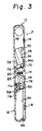
- the portable printer P comprises two elongated rectangular casings 10 and 12 pivotally connected to each other by hinges 14 provided at inner side edges of bottoms thereof, as shown in Fig. 2, so that the casings 10 and 12 can be opened as shown in Figs. 3 and 4, and as each of the casings 10 and 12 has a thickness of about one inch, the opened printer P can be easily received in a carrying bag, brief case or the like.
- the casings 10 and 12 are closed, as shown in Figs. 1 and 2.
- the casings 10 and 20 are provided with a steel piece 16 and a magnetic piece 18 held in recesses formed in inner walls thereof, respectively, these pieces 16 and 18 being in register with each other when the casings 10 and 12 are closed, whereby the casings 10 and 12 can be magnetically maintained in the closed condition during a printing operation of the printer P.
- the pieces 16 and 18 are attracted to each other with a suitable magnet force such that the casings 10 and 12 can be manually and easily separated from each other, as indicated by arrows 24 and 26 in Fig. 2.
- two magnetic pieces may be held in the recesses formed in the inner walls of the casings 10 and 12, and arranged so as to magnetically attract each other.
- the casings 10 and 20 are provided with two magnetic strips 20 and 22 held in recesses formed in the bottoms thereof. respectively, as best shown in Fig. 5, and arranged so as to magnetically attract each other when the casings 10 and 12 are in the open position, and thus the casings 10 and 12 can be magnetically maintained in the open condition while carrying the printer P.
- the casing 10 includes a carriage 28 movably mounted on a guide shaft 30 extended between and supported by side walls of the casing 10.
- the carriage 28 is moved along the guide shaft 30 by an suitable electric motor (not shown) such as a pulse motor, servo-motor or the like through the intermediary of a well-known drive mechanism (not shown).
- the motor and the drive mechanism are housed in the casing 10.
- the carriage 28 is provided with a thermal printing head 32, and a thermal ink ribbon cassette 34 is detachably mounted on the carriage 28 in such a manner that a thermal ink ribbon portion 34a exposed from the cassette 34 faces a printing face of the head 32.
- a flat platen 36 is provided in the casing 10 and is held in a recess formed in a shoulder portion 38 integrally extended from an inner surface of the inner wall thereof, in such a manner that the printing face is in contact with a flat surface of the platen 36.
- a paper guide member 40 is integrally extended from an inner surface of an outer wall of the casing 10 so that a guide surface of the paper guide member 40 is flush with the flat surface of the platen 36.
- the shoulder portion 38 provides a paper guide surface flush with the flat surface of the platen 36. As apparent from Fig. 2, these paper guide surfaces are sloped downward from the inner wall of the casing 10 toward the outer wall thereof.
- reference numeral 42 indicates a symbolically illustrated battery case in which suitable batteries (not shown) are housed.
- the casing 12 includes paper feed rollers 44 fixedly mounted on and equally spaced along a shaft 46 extended between and rotatably supported by side walls of the casing 12.
- the shaft 46 is driven in a direction indicated by an arrow 48 in Fig. 2, by a suitable electric motor (not shown) such as a pulse motor, servo motor or the like, housed in the casing 12.
- the casing 12 also includes the same number of pressure rollers 50, which are resiliently pressed against the paper feed rollers 46, respectively.
- the pressure rollers 50 are rotatably mounted on and spaced along a shaft 52 at the same pitch as the paper feed rollers 44, and the shaft 52 is then supported by bracket members 54 fixedly mounted on a shaft 56 extended between and rotatably supported by side walls of the casing 12.
- the shaft 56 is provided with torsion springs 58, each of which has two arms engaged with the corresponding bracket member 54 and the inner wall of the casing 12, respectively, so that each of the pressure rollers 50 is resiliently biased against the corresponding paper feed roller 44.
- the casing 12 is further provided with paper guide members 62 extended from an outer wall of the casing 12 to the inner wall thereof, and displacable between two adjacent paper feed rollers 46, respectively.
- Each of the paper guide members 62 has a guide surface sloped downward from the outer wall of the casing 12 toward the inner wall thereof, and when the casings 10 and 12 are closed as shown in Fig. 2, the guide surfaces of the paper guide members 62 are flush with the guide surface formed by the shoulder portion 38 of the casing 10.
- reference numeral 64 indicates a control circuit board for controlling a printing operation of the printer P
- reference numeral 66 indicates a battery switch button.
- a dummy hinge 68 is provided at the inner side edges of the bottoms of the casings 10 and 12, and a flat flexible electrical cable 69 (a part of which is shown by a broken line) is passed though an inside of the dummy hinge 68 to electrically connect the thermal head 32 and the carriage-drive motor to the control circuit board 64.
- the casing 10 has elongated openings 70 and 72 formed in the inner and outer walls thereof, respectively, and the casing 12 also has elongated openings 74 and 76 formed in the outer and inner walls thereof, respectively.
- the opening 74 can be closed by a paper guide tray 78 detachably pivoted to the outer wall of the casing 12 (Fig. 3).
- the openings 70 and 76 are in register with each other, and thus a cut sheet paper 77 can be guided along the above-mentioned paper guide surfaces through the openings 74, 76, 70, and 72, as shown in Fig. 6.
- the cut sheet paper 77 is intermittently fed by the paper feed rollers 44 in a feeding direction indicated by an arrow A in Fig. 2.
- the paper feed rollers 44 are continuously driven so that the paper can be discharged from the opening 72.
- the casings 10 and 12 are provided with extendable legs 80 and 82 receivable in rectangular recesses 84 and 86 formed in the bottoms of the casings 10 and 12, respectively.
- each of the extendable legs 80 and 82 is rotatably attached at one end thereof to one of pivot pins 88, 90 projected from a bottom surface of the recesses 84, 86, and thus can be moved between a first position (shown by a broken line) at which the legs 80, 82 are received in the recesses 84, 86, respectively, and a second position (shown by a solid line) at which the legs 80, 82 are extended from the outer bottom edges of the casings 10, 12.
- a first position shown by a broken line
- a second position shown by a solid line
- rounded projections 92, 94 are formed on an upper surface of the extendable legs 80, 82, respectively, at the free ends thereof.
- the rounded projections 92, 94 are snugly engaged in rounded recesses 96 and 98 formed in the bottom surface of the rectangular recesses 84, 86, so that the extendable legs 80, 82 cannot be arbitrarily moved from the first position (broken line) to the second position (solid line).
- the extendable legs 80 and 82 are extended to ensure a stable posture of the printer P. Nevertheless, if a conventional type cut sheet paper feeder is mounted on or attached to the printer P, the printer cannot be stable due to the additional weight of the feeder on the printer P.
- the cut sheet paper feeder F according to the present invention is arranged so as to receive and hold the printer P as shown Fig. 1, whereby the posture of the printer P can be made stable.
- the paper feeder F comprises a base frame 100 having a rectangular bottom plate 102, a pair of side walls 104 and 106 integrally extended from longer opposite side edges of the bottom plate 102, and a box-like casing member 108 disposed and fixed between the side walls 104 and 106.
- a top surface of the casing member serves as a surface for supporting the printer P.
- each of the casings 10 and 12 has a thickness of about one inch, and accordingly, the printer P has a thickness of about 2 inches when in the closed condition.
- a width of the casing member 108 and a distance between the side walls 104 and 106 are about 2 inches.
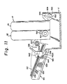
- the paper feeder F also comprises a paper feed tray 110 integrally attached to the side wall 106, and a stack of cut sheet papers 112 to be fed is received in the paper feed tray 110 (Fig. 11).
- the printer P When the printer P is mounted on the base frame 100, it must be correctly orientated so that the outer wall of the casing 12 faces the side wall 106, as shown in Fig. 1, i.e., the opening 74 for introducing the paper to be printed is directed toward the paper feed tray 110.
- two magnetic strips 114 and 116 are received and fixed in recesses formed in the top surface of the casing member 108, and are arranged so as to be magnetically attracted by the magnetic strips 20 and 22 of the printer P, respectively. Namely when the printer P is properly orientated and mounted on the base frame 100, the magnetic strips 114 and 116 face the magnetic strips 20 and 22 of the printer P, respectively, as shown in Fig.
- the box-like casing member 108 can be provided with positioning projections 118 projected from the top surface thereof, as shown in Fig. 7.
- the casing 12 of the printer P has two recesses 120 formed in the bottom thereof (Figs. 8 and 9), arranged to receive the projections 118 when the printer P is properly orientated and mounted on the base frame 100, as shown in Fig. 8.
- the projections 118 and the recesses 120 not only position the printer P in place, but also ensure that the printer P is correctly orientated. Namely, when the printer P is improperly orientated, the projections 118 cannot be received in the recesses 120, as shown in Fig. 9.
- another suitable means for positioning the printer P on the base frame 100 may be used.
- vertical grooves may be formed in the outer wall surfaces of the casings 10, 12 to receive vertical ridges formed on inner wall surfaces of the side walls 104, 106.
- the paper feed tray 110 is provided with three paper feed rollers 122 which are fixedly mounted on a shaft 124 rotatably supported by side walls 126 and 128 of the tray 110. Also, the paper feed tray 110 is provided with a movable plate member 130 received therein, as shown in Fig. 10, and the stack of cut sheet papers 112 is placed on the movable plate member 130, as shown in Fig. 11.
- the plate member 130 is rotatabty attached at a rear end portion thereof to pivot pins 132 projected from inner wall surfaces of the side wails 126 and 128, and is lifted about the pivot pins 132 by a compressed coil spring 134 restrained between a bottom of the tray 110 and the plate member 130, so that a front end portion of the plate member 130 is resiliently pressed against the paper feed rollers 122, as shown in Fig. 10. Accordingly, the stack of cut sheet papers 112 placed on the plate member 130 also is pressed against the paper feed rollers 122 (Figs. 13 and 14), and thus the uppermost cut sheet paper of the stack of cut sheet papers 112 can be fed therefrom by rotating the paper feed rollers 122 in a direction indicated by an arrow 136.
- the plate member 130 When the stack of cut sheet papers 112 is placed on the plate member 130, the plate member 130 must be pushed down against a resilient force of the compressed coil spring 134, to thereby separate the front end portion thereof from the paper feed rollers 122, and must be held at this lower level before the stack of cut sheet papers 112 can be easily and smoothly placed on the plate member 130 without hindrance by the paper feed rollers 122.
- the paper feed tray 110 is provided with a lock mechanism including an arm 138 pivoted at one end thereof to the side wall 126 of the tray 110, a lock pin 140 extended through a free end of the arm 138, and a lock lever 142 pivoted at a side wall 126 of the tray 110.
- An inner portion (not visible) of the lock pin 140 is engaged with a U-shaped member 144 fixedly attached to a lower surface of the plate member 130, and an outer portion of the lock pin 140 is engaged with the lock lever 142, as shown in Figs. 10 and 11.
- the lock lever 142 has a cam profile including two notches 142a and 142b. As apparent from Fig.
- the plate member 130 per se may be manually pushed down to the lower position, without using the lock lever 142, and in this case, preferably the lock lever 142 is rotatable in a clockwise direction (Fig. 10) by the force of gravity, whereby the outer portion of the lock pin 140 can be engaged with the notch 142b.
- the rotation of the lock lever 142 in the clockwise direction may be ensure by the force of a stretched coil spring 146 acting on an arm portion of the lock lever 142.
- reference 148 indicates a stop pin against which the arm portion of the lock lever 142 is abutted.
- the paper feeder F further comprises three paper discharge rollers 150 fixedly mounted on a shaft 152 rotatably supported by two bracket members 154 projected from an inner wall surface of the side wall 104 of the base frame 100, and a paper discharge roll member 156 cooperating with the rollers 150 and rotatably supported by the bracket members 154 to be extended in parallel with the shaft 152.
- a central portion of the roll member 156 is shown to be removed, to thus illustrate an overall appearance of the central roller 150, the roll member 156 is actually extended between the bracket members 154.
- Each of the paper feed rollers 150 has a generally D-shaped cross section, and thus a circumferential surface of the roller 150 is formed by a flat surface portion 150a and a circular surface portion 150b.
- the flat surface portions 150a of the rollers 150 are positioned in the same phase. Namely, if one of the flat surface portions 150a is extended as a geometrical plane, this geometrical plane includes the other flat surface portions.
- the circular surface portions 150b of the rollers 150 are engageable with the paper discharge roll member 156. Namely, the roll member 156 can be rotated only while the circular surface portions 150b are engaged with the paper discharge roll member 156.
- the box-like casing member 108 is longitudinally shorter than the bottom plate 102, and thus an open space is formed at one end side of the base frame 100 for receiving an electric motor 158 such as a pulse motor, servo motor or the like a first gear train 160, and a second gear train 162 therein.
- the electric motor 158 is attached to the bottom plate 102 by two screws 164 (only one is visible in Fig. 7) through a spacer sleeve 166, and can be driven in normal and reverse directions as indicated by arrows N and R in Fig. 7, respectively.
- An output gear (not visible) of the motor 158 is engaged with input gears (not visible) of the first and second gear trains 160 and 162.
- the first gear train 160 terminates at an output gear thereof, which is carried by a pulley 168 pivoted to the side wall 128 of the paper feed tray 110, and the pulley 168 is operationally connected to a pulley 170 through a drive belt 172.
- the pulley 170 is mounted on an outer end of the shaft 124 projected from the side wall 128 of the paper feed tray 110, and is provided with a one-way clutch (not shown) therein.
- This one-way clutch is arranged so that the shaft 124 can be rotated in only one direction indicated by an arrow 174 in Fig. 7. Namely, the paper feed rollers 122 can be rotated only in the direction indicated by the arrow 136 (Figs. 10 and 11).
- the first gear train 160 is arranged so that, when the motor 158 is normally driven in the direction indicated by the arrow N, the pulley 170, and therefore, the shaft 124, is rotated in the direction indicated by the arrow 174.
- the motor 158 is reversely driven in the direction indicated by the arrow R, the pulley 170 is reversely rotated, but the shaft 124 cannot be reversely rotated due to the one-way clutch provided in the pulley 170.
- the paper feed rollers 122 can be rotated in the normal direction (136) so that the cut sheet paper can be fed, but a rotation of the rollers 122 in the reverse direction is prevented.
- the drive belt 172 is tensed by a tension mechanism including a two-armed lever 176 pivoted at the side wall 128 of the paper feed tray 110, a pulley 178 pivoted at and supported by one arm of the two-armed lever 176, and a stretched coil spring 180 acting on the other arm of the two-armed lever 176.
- the pulley 178 is engaged with the drive belt 172 by a spring force of the stretched coil spring 180, so that the drive belt 172 can be always tensed, and thus a rotational movement can be transmitted from the pulley 168 to the pulley 170.
- the second gear train 162 terminates at an output gear carried by an one end of the shaft 156 on which the paper discharge rollers 150 are fixedly mounted, and is arranged so that, when the motor 158 is driven in the reverse direction (R), the shaft 152, and therefore, the paper discharge rollers 150, are rotated in a normal direction as indicated by an arrow 182, whereby the cut sheet paper is discharged from an outlet opening 184 formed in the side wall 104 of the base frame 100.
- the motor 158 is driven in the normal direction (N)
- the paper discharge rollers 150 are rotated in a reverse direction as indicated by an arrow 186.
- a control circuit 188 for controlling a paper feed operation of the paper feeder F is shown as a block, but the control circuit 188 is actually housed as a control circuit board in the box-like casing member 108.
- the control circuit board includes a drive circuit for the motor 158 shown as a block in Fig. 13 and 14, and a microcomputer, etc..
- the control circuit 188 is electrically connected to a contact switch 190 disposed in the vicinity of a nip between the paper feed rollers 44 and the pressure rollers 50 of the printer P.
- the contact switch 190 is made ON when the cut sheet paper passes through the nip between the paper feed rollers 44 and the pressure roller 50.
- the control circuit 188 is electrically connected to a photo-sensor 190 for detecting an extending of a positioning element 194 is extended from the shaft 152 on which the paper discharge rollers 150 are fixedly mounted. When the positioning element 194 is detected by the photo-sensor 192 during the rotation of the shaft 152, the flat surface portions 150a of the paper discharge rollers 150 are directed toward the shaft 152, as shown in Fig. 13.
- the photo-sensor 192 includes a light emitting element (not shown) such as an LED, and a light receiving element (not shown) for receiving light emitted from the light emitting element.
- a detecting signal output from the photo-sensor is changed, for example, from a low level to a high level.
- the control circuit 188 is further electrically connected to the control circuit (64) of the printer P through an interface, so that character code data, and control signals, etc., are fed from the control circuit (64) to the control circuit 188.
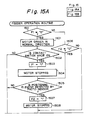
- the feeder operation routine is executed by interruptions output at very short intervals, for example, 4 ms, and the execution of the routine is started when the control circuit 188 receives a printing-ready signal from the control circuit (64) of the printer P showing that the printer P is ready for printing.
- step 150 it is determined whether or not a flag F1 is "0" or "1". Since the flag F1 is initially made “0”, the control proceeds to step 1501 in which the motor 158 is driven in the normal direction (N), and thus the cut sheet paper is fed from the stack 112 to the printer P by the rotation of the paper feed rollers in the normal direction (136). Then, at step 1502, it is determined whether the contact switch 190 is made ON. Namely, it is determined whether or not a leading edge of the paper has reached the contact switch 190. At this stage, since the leading edge of the paper does not reach the contact switch 190, the routine is once completed.
- step 1502 the contact switch 190 is turned ON and the control proceeds to step 1503 in which the flag F1 is made "1". Note, after the contact switch 190 is turned ON, the paper is printed by the printer P.
- step 1504 the motor 158 is driven in the reverse direction (R) so that the rotational direction of the paper discharge rollers 150 is changed from the reverse direction (186) to the normal direction (182), but there is no paper to be discharged at this stage.
- step 1505 it is determined whether or not the positioning element 194 is detected by the photo-sensor 192. Note, as mentioned above, the detection of the positioning element 194 is carried out by a change of the output signal of the photo-sensor 192 from the low level to the high level. If the positioning element 194 is not detected by the photo-sensor 192, the routine is once completed. When the routine is executed again after 4 ms, the control proceeds from step 1501 to step 1506 in which it is determined whether a flag F2 is "0" or "1".
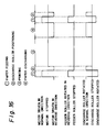
- step 1505 the control proceeds to step 1505. Thereafter, although the routine is repeatedly executed at intervals of 4 ms, the control does not further proceed until the positioning element 194 is detected by the photo-sensor 192, i.e., the flat surface portions 150a of the paper discharge rollers 150 are directed toward the paper discharge roll member 156. Note, during this time, the rotation of the paper feed rollers 122 is stopped due to the one-way clutch provided in the pulley 170, as shown in Fig. 16.
- step 1505 when the positioning element 194 is detected by the photo-sensor 192, the motor 158 is stopped, and the control proceeds to step 1507 in which the flag F2 is made "1". Then, at step 1508, the motor 158 is stopped, and accordingly, the paper feed rollers 150 are also stopped, so that the flat surface portions 150a of the paper discharge rollers 150 are directed toward the paper discharge roll member 156, and thus a space 196 is formed between the paper discharge rollers 150 and the paper discharge roll member 156, as shown in Figs. 13. At step 1509, it is determined whether or not the contact switch 190 is made OFF, i.e., the printing by the printer P is completed. If the printing is not completed, the routine is once completed.
- the paper is moved by the paper feed rollers 44 and the pressure rollers 50 of the printer P toward the outlet opening 184 formed in the side wall 104 of the base frame 100, and the forward portion of the paper is extended from the outlet opening 184 through the space 196 just before the printing is completed. It can be easily understood that the formation of the flat surface portions 150a on the paper discharge rollers 150 is directed toward the passage of the paper between the paper discharge rollers 150 and the paper discharge roll member 156 during the printing operation.
- step 1509 if the contact switch 190 is made OFF, i.e., if the printing is completed, the control proceeds to step 1510 in which the motor is driven in the reverse direction (R) so that the paper discharge rollers 150 are rotated in the normal direction (182). Accordingly, the circular surface portions 150b of the rollers 150 are engaged with the paper discharge roll member 156, through the intermediary of the paper, whereby the paper is moved by the rotation of the rollers 150 to be discharged from the outlet opening 184.
- step 1511 a counter C is incremented by 1, and at step 1512, it is determined whether or not the count number of the counter C is larger than a number T corresponding to a time sufficient for the complete discharge of the paper by the rotation of the paper discharge rollers 150.
- the number T is made 500 (2000/4).
- the routine is once completed. Thereafter, although the routine is repeatedly executed at intervals of 4 ms, the control does not further proceed until the count number of the counter C reaches 500.
- step 1512 when the count number of the counter C reaches 500, the control proceeds to step 1513 in which the motor 150 is stopped. Then, at the step 1514, the counter C is reset, and at steps 1515 and 1516, the flags F1 and F2 are made "0".
- control circuit 188 When the control circuit 188 again receives the printing-ready signal from the control circuit (64) of the printer P, the paper is fed to and discharged from the printer P in the manner as mentioned above.
- the drive motor 158 is commonly used for driving the paper feed rollers 122 and the paper discharge rollers 150, the paper feeder F can be compactly constructed.
- control circuit 188 per se includes the microcomputer for controlling the drive circuit for the motor 158, this drive circuit may be controlled by a controller of the printer P, in this case the microcomputer can be of course omitted from the control circuit 188.
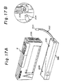
- FIG 17A shows a re-chargeable battery pack 198 on which the printer P can be mounted.
- the printer P When the printer P is mounted on the battery pack 198, it must be correctly orientated ant positioned with respect to the battery pack, and to this end, positioning recesses 120 formed in the bottom of the printer casing 12 are utilised.
- the battery pack 198 is provided with positioning projections 200 formed on a top surface thereof and arranged in the same manner as the projections 118 formed on the top surface of the box-like casing member 108.
- the battery pack is also provided with a power supply cord 202 having a connector 204 at a free end thereof. After the printer P is mounted on the battery pack 198, the connector 204 of the power supply cord 202 is joined to a socket 206 provided in a side wall of the printer casing 12, as best shown in Fig. 17B.
Landscapes
- Sheets, Magazines, And Separation Thereof (AREA)
- Handling Of Cut Paper (AREA)
- Delivering By Means Of Belts And Rollers (AREA)
Applications Claiming Priority (2)
| Application Number | Priority Date | Filing Date | Title |
|---|---|---|---|
| JP3008908A JP2984066B2 (ja) | 1991-01-29 | 1991-01-29 | プリンタ用自動給紙装置 |
| JP8908/91 | 1991-01-29 |
Publications (3)
| Publication Number | Publication Date |
|---|---|
| EP0497571A2 true EP0497571A2 (fr) | 1992-08-05 |
| EP0497571A3 EP0497571A3 (en) | 1993-05-19 |
| EP0497571B1 EP0497571B1 (fr) | 1997-04-16 |
Family
ID=11705775
Family Applications (1)
| Application Number | Title | Priority Date | Filing Date |
|---|---|---|---|
| EP92300736A Expired - Lifetime EP0497571B1 (fr) | 1991-01-29 | 1992-01-29 | Alimentation en papier pour imprimante portable |
Country Status (4)
| Country | Link |
|---|---|
| US (2) | US5423529A (fr) |
| EP (1) | EP0497571B1 (fr) |
| JP (1) | JP2984066B2 (fr) |
| DE (1) | DE69218985T2 (fr) |
Cited By (4)
| Publication number | Priority date | Publication date | Assignee | Title |
|---|---|---|---|---|
| EP0540301A3 (en) * | 1991-10-31 | 1993-11-18 | Canon Kk | Foladable compact recording apparatus |
| EP0901907A1 (fr) * | 1997-09-02 | 1999-03-17 | Hewlett-Packard Company | Rouleau d'alimentation amovible pour imprimante de bureau |
| EP0879706A3 (fr) * | 1997-05-23 | 1999-08-18 | Canon Kabushiki Kaisha | Appareil d'enregistrement |
| US10882706B2 (en) | 2015-10-30 | 2021-01-05 | Hewlett-Packard Development Company, L.P. | Photo cassette for a mobile printer |
Families Citing this family (39)
| Publication number | Priority date | Publication date | Assignee | Title |
|---|---|---|---|---|
| JP2984066B2 (ja) * | 1991-01-29 | 1999-11-29 | 富士通アイソテック株式会社 | プリンタ用自動給紙装置 |
| US6786420B1 (en) | 1997-07-15 | 2004-09-07 | Silverbrook Research Pty. Ltd. | Data distribution mechanism in the form of ink dots on cards |
| US6618117B2 (en) | 1997-07-12 | 2003-09-09 | Silverbrook Research Pty Ltd | Image sensing apparatus including a microcontroller |
| US6624848B1 (en) | 1997-07-15 | 2003-09-23 | Silverbrook Research Pty Ltd | Cascading image modification using multiple digital cameras incorporating image processing |
| US6690419B1 (en) | 1997-07-15 | 2004-02-10 | Silverbrook Research Pty Ltd | Utilising eye detection methods for image processing in a digital image camera |
| US7110024B1 (en) | 1997-07-15 | 2006-09-19 | Silverbrook Research Pty Ltd | Digital camera system having motion deblurring means |
| US20040119829A1 (en) | 1997-07-15 | 2004-06-24 | Silverbrook Research Pty Ltd | Printhead assembly for a print on demand digital camera system |
| US6879341B1 (en) | 1997-07-15 | 2005-04-12 | Silverbrook Research Pty Ltd | Digital camera system containing a VLIW vector processor |
| JPH11198495A (ja) * | 1997-11-11 | 1999-07-27 | Brother Ind Ltd | 画像形成装置 |
| US6382858B1 (en) * | 1997-11-14 | 2002-05-07 | Canon Kabushiki Kaisha | Sheet material conveying apparatus and recording apparatus |
| JP3526209B2 (ja) * | 1998-04-15 | 2004-05-10 | キヤノン株式会社 | 給紙装置及びこれを備えた画像形成装置 |
| JP3697059B2 (ja) * | 1998-04-15 | 2005-09-21 | キヤノン株式会社 | 画像形成装置 |
| US6567187B1 (en) * | 1998-04-15 | 2003-05-20 | Canon Kabushiki Kaisha | Printing apparatus and feeding control method |
| US6200043B1 (en) | 1998-04-15 | 2001-03-13 | Canon Kabushiki Kaisha | Sheet feeding apparatus and image forming apparatus having such sheet feeding apparatus |
| AUPP702098A0 (en) | 1998-11-09 | 1998-12-03 | Silverbrook Research Pty Ltd | Image creation method and apparatus (ART73) |
| AUPP702198A0 (en) * | 1998-11-09 | 1998-12-03 | Silverbrook Research Pty Ltd | Image creation method and apparatus (ART79) |
| AUPQ056099A0 (en) * | 1999-05-25 | 1999-06-17 | Silverbrook Research Pty Ltd | A method and apparatus (pprint01) |
| AUPQ439299A0 (en) | 1999-12-01 | 1999-12-23 | Silverbrook Research Pty Ltd | Interface system |
| JP3764328B2 (ja) * | 2000-09-19 | 2006-04-05 | 株式会社Pfu | 給紙装置 |
| DE10056444C1 (de) * | 2000-11-14 | 2001-10-31 | Eberhard Wahl | Papierführung für einen Drucker |
| JP4387651B2 (ja) * | 2002-10-07 | 2009-12-16 | キヤノン株式会社 | 記録装置 |
| US7517046B2 (en) * | 2005-05-09 | 2009-04-14 | Silverbrook Research Pty Ltd | Mobile telecommunications device with printhead capper that is held in uncapped position by media |
| US7284921B2 (en) | 2005-05-09 | 2007-10-23 | Silverbrook Research Pty Ltd | Mobile device with first and second optical pathways |
| USD544532S1 (en) * | 2005-09-09 | 2007-06-12 | Brother Industries, Ltd. | Printer |
| USD563413S1 (en) * | 2006-07-05 | 2008-03-04 | Pfu Limited | Scanner |
| KR101314234B1 (ko) * | 2006-07-25 | 2013-10-04 | 삼성전자주식회사 | 휴대용 화상형성장치 |
| USD588631S1 (en) * | 2006-09-25 | 2009-03-17 | Seiko Epson Corporation | Printer unit for duplex printing |
| US7850300B2 (en) * | 2007-01-04 | 2010-12-14 | Kabushiki Kaisha Toshiba | Image forming apparatus |
| USD579938S1 (en) * | 2007-09-13 | 2008-11-04 | Digital Business Processes, Inc. | Sheet scanner |
| JP2009286517A (ja) * | 2008-05-27 | 2009-12-10 | Kyocera Mita Corp | 給紙装置及びこれを搭載した原稿搬送装置、画像形成装置 |
| USD643039S1 (en) * | 2010-12-08 | 2011-08-09 | Hewlett-Packard Development Company, L.P. | Multi-function imaging and printing device |
| USD689867S1 (en) * | 2011-08-09 | 2013-09-17 | Canon Denshi Kabushiki Kaisha | Scanner |
| USD682834S1 (en) * | 2011-09-21 | 2013-05-21 | Canon Denshi Kabushiki Kaisha | Scanner |
| USD699726S1 (en) * | 2012-10-19 | 2014-02-18 | Brother Industries, Ltd. | Scanner |
| USD709071S1 (en) * | 2012-11-06 | 2014-07-15 | Canon Denshi Kabushiki Kaisha | Scanner |
| USD706269S1 (en) * | 2012-12-13 | 2014-06-03 | Hewlett-Packard Development Company, L.P. | Imaging device |
| JP1641970S (fr) * | 2019-03-14 | 2019-09-24 | ||
| US20230022827A1 (en) * | 2021-07-21 | 2023-01-26 | Hewlett-Packard Development Company, L.P. | Direct Printing and Printer |
| CN116409065B (zh) * | 2023-02-13 | 2024-01-30 | 珠海恒盛条码设备有限公司 | 一种便携打印系统及应用方法 |
Family Cites Families (26)
| Publication number | Priority date | Publication date | Assignee | Title |
|---|---|---|---|---|
| US1236234A (en) * | 1917-03-30 | 1917-08-07 | Oscar R Troje | Toy building-block. |
| US2615738A (en) * | 1950-03-18 | 1952-10-28 | Bailey Meter Co | Linkage connector |
| US3043289A (en) * | 1960-03-09 | 1962-07-10 | Fox Morris | Safety guard for gas range on-and-off valves |
| US4494659A (en) * | 1983-05-03 | 1985-01-22 | Visu-Flex Company | Compressor for microfiche cards and the like |
| US4484682A (en) * | 1983-06-06 | 1984-11-27 | Crow Robert T | Container with magnet for holding it in position |
| EP0137715B1 (fr) * | 1983-09-12 | 1988-01-07 | Tokyo Electric Co. Ltd. | Imprimante |
| JPS60196379A (ja) * | 1984-03-21 | 1985-10-04 | Fujitsu Ltd | プリンタ装置 |
| US4680674A (en) * | 1984-07-16 | 1987-07-14 | Moore Fergus E | Modular computer system with integral electronic bus |
| IT1196758B (it) * | 1984-11-19 | 1988-11-25 | Olivetti & Co Spa | Alimentatore di supporti di stampa per una macchina per scrivere o simili macchine da ufficio |
| US4722623A (en) * | 1985-03-09 | 1988-02-02 | Oki Electric Industry Co., Ltd. | Printer and paper insertion device suitable therefor |
| JPS624046A (ja) * | 1985-06-26 | 1987-01-10 | 株式会社 サト− | ユニツト式サ−マルラベルプリンタ |
| JPS6213370A (ja) * | 1985-07-12 | 1987-01-22 | Ricoh Co Ltd | プリンタの給紙装置 |
| JPS6246823A (ja) * | 1985-08-23 | 1987-02-28 | Nec Corp | シ−トフイ−ダ |
| JPS62136437A (ja) * | 1985-12-04 | 1987-06-19 | Ricoh Co Ltd | 印字装置 |
| US4966356A (en) * | 1987-09-30 | 1990-10-30 | Fujitsu Limited | Apparatus for selectively feeding cut sheets in a recording machine |
| JPH0192639A (ja) * | 1987-10-05 | 1989-04-11 | Kanzaki Paper Mfg Co Ltd | 粘着力測定装置 |
| EP0526916A2 (fr) * | 1987-11-10 | 1993-02-10 | Mita Industrial Co. Ltd. | Appareil de formation d'images |
| JP2601674B2 (ja) * | 1988-01-27 | 1997-04-16 | 松下電器産業株式会社 | 給紙装置 |
| US5028834A (en) * | 1988-07-21 | 1991-07-02 | Brother Kogyo Kabushiki Kaisha | Device for magnifying displacement of piezoelectric element and method of producing same |
| US4926365A (en) * | 1988-08-26 | 1990-05-15 | Great Electronics Corporation | Portable computer system |
| US5028934A (en) * | 1988-10-31 | 1991-07-02 | Seiko Epson Corporation | Hand-held portable printing system |
| US4904100A (en) * | 1988-12-05 | 1990-02-27 | Eastman Kodak Company | Cartridge and printer system for using roll print media |
| JP2515595B2 (ja) * | 1989-09-18 | 1996-07-10 | キヤノン株式会社 | 自動給紙装置 |
| JP2857498B2 (ja) * | 1990-06-28 | 1999-02-17 | 富士通アイソテック株式会社 | ポータブルプリンタ |
| JP2984066B2 (ja) * | 1991-01-29 | 1999-11-29 | 富士通アイソテック株式会社 | プリンタ用自動給紙装置 |
| US5138373A (en) * | 1991-12-16 | 1992-08-11 | Xerox Corporation | Copier or printer component position floating magnetic actuator |
-
1991
- 1991-01-29 JP JP3008908A patent/JP2984066B2/ja not_active Expired - Fee Related
-
1992
- 1992-01-29 DE DE69218985T patent/DE69218985T2/de not_active Expired - Fee Related
- 1992-01-29 EP EP92300736A patent/EP0497571B1/fr not_active Expired - Lifetime
-
1994
- 1994-10-14 US US08/323,055 patent/US5423529A/en not_active Expired - Fee Related
-
1995
- 1995-04-05 US US08/417,244 patent/US5531431A/en not_active Expired - Fee Related
Cited By (5)
| Publication number | Priority date | Publication date | Assignee | Title |
|---|---|---|---|---|
| EP0540301A3 (en) * | 1991-10-31 | 1993-11-18 | Canon Kk | Foladable compact recording apparatus |
| US5475413A (en) * | 1991-10-31 | 1995-12-12 | Canon Kabushiki Kaisha | Portable recording apparatus having relatively movable housing sections |
| EP0879706A3 (fr) * | 1997-05-23 | 1999-08-18 | Canon Kabushiki Kaisha | Appareil d'enregistrement |
| EP0901907A1 (fr) * | 1997-09-02 | 1999-03-17 | Hewlett-Packard Company | Rouleau d'alimentation amovible pour imprimante de bureau |
| US10882706B2 (en) | 2015-10-30 | 2021-01-05 | Hewlett-Packard Development Company, L.P. | Photo cassette for a mobile printer |
Also Published As
| Publication number | Publication date |
|---|---|
| US5423529A (en) | 1995-06-13 |
| DE69218985T2 (de) | 1997-07-24 |
| EP0497571A3 (en) | 1993-05-19 |
| US5531431A (en) | 1996-07-02 |
| EP0497571B1 (fr) | 1997-04-16 |
| JPH05221538A (ja) | 1993-08-31 |
| JP2984066B2 (ja) | 1999-11-29 |
| DE69218985D1 (de) | 1997-05-22 |
Similar Documents
| Publication | Publication Date | Title |
|---|---|---|
| EP0497571B1 (fr) | Alimentation en papier pour imprimante portable | |
| US5411339A (en) | Portable printer and cartridge therefor | |
| US4826558A (en) | Electrically-operated labeler | |
| EP0297566B1 (fr) | Appareil de lecture d'un original | |
| JP2690659B2 (ja) | ラベルプリンタ | |
| EP2093071B1 (fr) | Imprimantes portables et procédés | |
| US10363764B2 (en) | Portable printer and methods | |
| US20060175747A1 (en) | Media handling system | |
| JP2781099B2 (ja) | スタッカ | |
| JP2024106463A (ja) | 電子機器 | |
| JP3296969B2 (ja) | スタッカ | |
| JP2945212B2 (ja) | ラベル剥離装置 | |
| JP3209043B2 (ja) | 帯紙送り装置 | |
| JPH0612047U (ja) | ハンディプリンタ | |
| JP3186579B2 (ja) | スタッカ | |
| US20240212413A1 (en) | Article supply device | |
| JP2860622B2 (ja) | シート計数機 | |
| JPH06286266A (ja) | プリンタ | |
| JP4559647B2 (ja) | スタッカおよびその制御方法 | |
| JP2021178700A (ja) | 給紙トレイおよび印刷装置 | |
| JPS6021275A (ja) | 印字装置 | |
| JPS6360828A (ja) | 給紙装置 | |
| JPH1120282A (ja) | 熱転写印字装置 | |
| JPS6312441A (ja) | カセツト式ラベルプリンタ | |
| JPH01176738A (ja) | 給紙装置 |
Legal Events
| Date | Code | Title | Description |
|---|---|---|---|
| PUAI | Public reference made under article 153(3) epc to a published international application that has entered the european phase |
Free format text: ORIGINAL CODE: 0009012 |
|
| AK | Designated contracting states |
Kind code of ref document: A2 Designated state(s): DE FR GB |
|
| PUAL | Search report despatched |
Free format text: ORIGINAL CODE: 0009013 |
|
| AK | Designated contracting states |
Kind code of ref document: A3 Designated state(s): DE FR GB |
|
| 17P | Request for examination filed |
Effective date: 19931111 |
|
| 17Q | First examination report despatched |
Effective date: 19950210 |
|
| GRAG | Despatch of communication of intention to grant |
Free format text: ORIGINAL CODE: EPIDOS AGRA |
|
| GRAH | Despatch of communication of intention to grant a patent |
Free format text: ORIGINAL CODE: EPIDOS IGRA |
|
| GRAH | Despatch of communication of intention to grant a patent |
Free format text: ORIGINAL CODE: EPIDOS IGRA |
|
| GRAA | (expected) grant |
Free format text: ORIGINAL CODE: 0009210 |
|
| AK | Designated contracting states |
Kind code of ref document: B1 Designated state(s): DE FR GB |
|
| REF | Corresponds to: |
Ref document number: 69218985 Country of ref document: DE Date of ref document: 19970522 |
|
| ET | Fr: translation filed | ||
| PLBE | No opposition filed within time limit |
Free format text: ORIGINAL CODE: 0009261 |
|
| 26N | No opposition filed | ||
| REG | Reference to a national code |
Ref country code: GB Ref legal event code: IF02 |
|
| PGFP | Annual fee paid to national office [announced via postgrant information from national office to epo] |
Ref country code: FR Payment date: 20020110 Year of fee payment: 11 |
|
| PGFP | Annual fee paid to national office [announced via postgrant information from national office to epo] |
Ref country code: GB Payment date: 20020130 Year of fee payment: 11 |
|
| PGFP | Annual fee paid to national office [announced via postgrant information from national office to epo] |
Ref country code: DE Payment date: 20020227 Year of fee payment: 11 |
|
| PG25 | Lapsed in a contracting state [announced via postgrant information from national office to epo] |
Ref country code: GB Free format text: LAPSE BECAUSE OF NON-PAYMENT OF DUE FEES Effective date: 20030129 |
|
| PG25 | Lapsed in a contracting state [announced via postgrant information from national office to epo] |
Ref country code: DE Free format text: LAPSE BECAUSE OF NON-PAYMENT OF DUE FEES Effective date: 20030801 |
|
| GBPC | Gb: european patent ceased through non-payment of renewal fee | ||
| PG25 | Lapsed in a contracting state [announced via postgrant information from national office to epo] |
Ref country code: FR Free format text: LAPSE BECAUSE OF NON-PAYMENT OF DUE FEES Effective date: 20030930 |
|
| REG | Reference to a national code |
Ref country code: FR Ref legal event code: ST |