EP0497582A2 - Procédé pour la fabrication d'une feuille de caoutchouc avec des motifs à rainures formés sur une de ses faces - Google Patents
Procédé pour la fabrication d'une feuille de caoutchouc avec des motifs à rainures formés sur une de ses faces Download PDFInfo
- Publication number
- EP0497582A2 EP0497582A2 EP92300770A EP92300770A EP0497582A2 EP 0497582 A2 EP0497582 A2 EP 0497582A2 EP 92300770 A EP92300770 A EP 92300770A EP 92300770 A EP92300770 A EP 92300770A EP 0497582 A2 EP0497582 A2 EP 0497582A2
- Authority
- EP
- European Patent Office
- Prior art keywords
- rotating roll
- rubber
- rubber sheet
- roll
- outer peripheral
- Prior art date
- Legal status (The legal status is an assumption and is not a legal conclusion. Google has not performed a legal analysis and makes no representation as to the accuracy of the status listed.)
- Withdrawn
Links
Images


Classifications
-
- B—PERFORMING OPERATIONS; TRANSPORTING
- B29—WORKING OF PLASTICS; WORKING OF SUBSTANCES IN A PLASTIC STATE IN GENERAL
- B29C—SHAPING OR JOINING OF PLASTICS; SHAPING OF MATERIAL IN A PLASTIC STATE, NOT OTHERWISE PROVIDED FOR; AFTER-TREATMENT OF THE SHAPED PRODUCTS, e.g. REPAIRING
- B29C43/00—Compression moulding, i.e. applying external pressure to flow the moulding material; Apparatus therefor
- B29C43/22—Compression moulding, i.e. applying external pressure to flow the moulding material; Apparatus therefor of articles of indefinite length
- B29C43/222—Compression moulding, i.e. applying external pressure to flow the moulding material; Apparatus therefor of articles of indefinite length characterised by the shape of the surface
-
- B—PERFORMING OPERATIONS; TRANSPORTING
- B29—WORKING OF PLASTICS; WORKING OF SUBSTANCES IN A PLASTIC STATE IN GENERAL
- B29C—SHAPING OR JOINING OF PLASTICS; SHAPING OF MATERIAL IN A PLASTIC STATE, NOT OTHERWISE PROVIDED FOR; AFTER-TREATMENT OF THE SHAPED PRODUCTS, e.g. REPAIRING
- B29C43/00—Compression moulding, i.e. applying external pressure to flow the moulding material; Apparatus therefor
- B29C43/22—Compression moulding, i.e. applying external pressure to flow the moulding material; Apparatus therefor of articles of indefinite length
- B29C43/24—Calendering
-
- B—PERFORMING OPERATIONS; TRANSPORTING
- B29—WORKING OF PLASTICS; WORKING OF SUBSTANCES IN A PLASTIC STATE IN GENERAL
- B29C—SHAPING OR JOINING OF PLASTICS; SHAPING OF MATERIAL IN A PLASTIC STATE, NOT OTHERWISE PROVIDED FOR; AFTER-TREATMENT OF THE SHAPED PRODUCTS, e.g. REPAIRING
- B29C43/00—Compression moulding, i.e. applying external pressure to flow the moulding material; Apparatus therefor
- B29C43/32—Component parts, details or accessories; Auxiliary operations
- B29C43/44—Compression means for making articles of indefinite length
- B29C43/46—Rollers
-
- B—PERFORMING OPERATIONS; TRANSPORTING
- B29—WORKING OF PLASTICS; WORKING OF SUBSTANCES IN A PLASTIC STATE IN GENERAL
- B29C—SHAPING OR JOINING OF PLASTICS; SHAPING OF MATERIAL IN A PLASTIC STATE, NOT OTHERWISE PROVIDED FOR; AFTER-TREATMENT OF THE SHAPED PRODUCTS, e.g. REPAIRING
- B29C48/00—Extrusion moulding, i.e. expressing the moulding material through a die or nozzle which imparts the desired form; Apparatus therefor
- B29C48/03—Extrusion moulding, i.e. expressing the moulding material through a die or nozzle which imparts the desired form; Apparatus therefor characterised by the shape of the extruded material at extrusion
- B29C48/07—Flat, e.g. panels
- B29C48/08—Flat, e.g. panels flexible, e.g. films
-
- B—PERFORMING OPERATIONS; TRANSPORTING
- B29—WORKING OF PLASTICS; WORKING OF SUBSTANCES IN A PLASTIC STATE IN GENERAL
- B29C—SHAPING OR JOINING OF PLASTICS; SHAPING OF MATERIAL IN A PLASTIC STATE, NOT OTHERWISE PROVIDED FOR; AFTER-TREATMENT OF THE SHAPED PRODUCTS, e.g. REPAIRING
- B29C48/00—Extrusion moulding, i.e. expressing the moulding material through a die or nozzle which imparts the desired form; Apparatus therefor
- B29C48/25—Component parts, details or accessories; Auxiliary operations
- B29C48/36—Means for plasticising or homogenising the moulding material or forcing it through the nozzle or die
- B29C48/465—Means for plasticising or homogenising the moulding material or forcing it through the nozzle or die using rollers
-
- B—PERFORMING OPERATIONS; TRANSPORTING
- B29—WORKING OF PLASTICS; WORKING OF SUBSTANCES IN A PLASTIC STATE IN GENERAL
- B29K—INDEXING SCHEME ASSOCIATED WITH SUBCLASSES B29B, B29C OR B29D, RELATING TO MOULDING MATERIALS OR TO MATERIALS FOR MOULDS, REINFORCEMENTS, FILLERS OR PREFORMED PARTS, e.g. INSERTS
- B29K2021/00—Use of unspecified rubbers as moulding material
Definitions
- the present invention relates to a method of manufacturing a rubber sheet with rugged patterns formed on its one side surface portion and, more particularly, to a method of manufacturing a rubber sheet used for a tire manufactured by vulcanizing a green tire constituted by laminated rubber sheets.
- nonvulcanized rubber sheets having tackiness or tacky surfaces and having wide breadths are used.
- the nonvulcanized rubber sheets include an inner liner made of a nonvulcanized rubber, a cord coated with a nonvulcanized rubber. These rubber sheets and tread compound rubber are applied to an outer peripheral surtace of a cylindrical drum for example in above described order and adhered to each other under pressure to form a so-called green case or green tire. Then, the green case or the green tire is vulcanized. In the forming process of the green case or the green tire, after the nonvulcanized rubber sheets are applied to the drum and laminated each other, the laminated rubber sheets are adhered to each other by a stitching roll, etc.
- the calender 1 comprises an upper roll 3A and a lower roll 3B which are rotated by motors (not shown).
- a heated raw rubber; i.e., a warmed up raw rubber 4 is fed to the calender 1 and allowed to pass through a clearance between the upper roll 3A and the tower roll 3B so that a rubber sheet 5 made of the raw rubber 4 is extruded from the calender 1.
- the rubber sheet 5 is conveyed from the calender 1 to the patterning former 2 by a conveyor belt 6.
- the patterning former 2 comprises a smooth roll 8 and a ridge roll 7 having elongated grooves formed on its outer peripheral surface portion.
- the conveyed rubber sheet 5 is fed to the patterning former 2 and allowed to pass through a clearance between the ridge roll 7 and the smooth roll 8 so that a rugged rubber sheet 9 made of the rubber sheet 5 is extruded from the patterning former 2.
- the groove patterns of the ridge roll 7 are transferred to one side surface portion of the rubber sheet 5. Therefore, the rugged rubber sheet 9 has protrusion patterns as rugged patterns formed on its one side surface portion.
- a distance between the calender 1 and the patterning former 2 is so long that the rubber sheet 5 is cooled and hardened during the conveyance of the rubber sheet 5 by the conveyor belt 6. Therefore, the pliability of the rubber sheet 5 is reduced, thereby causing a difficulty in transferring the groove patterns to the rubber sheet 5.
- the rubber sheet 5 is a so-called contour rubber sheet
- the contact conditions includes the pressure applied to the rubber sheet 5 by the ridge roll 7, the time to apply the pressure, the pliability of the rubber sheet 5 and the like. It is also necessary to operate many adjustments at the start of the patterning process, thereby making it difficult to determine the conditions of the patterning process.
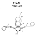
- the rugged patterns 14A of the bottom roll 14 apply the frictional force to the cord fabric 15 and force the rubber lamina 16 previously formed for cementing to be sunk into the cord fabric 15. At the same time, the rugged patterns 14A are transferred to the one side surface portion of the cord fabric 15 coated with the rubber.
- the rubber sheet 16 having an undulated surface i.e., the so-called contour rubber sheet 16
- every change of the tire size makes necessary the replacement of the contour roll, thereby requiring a long time and much labor for the replacement and causing a difficulty in operating the replacement.
- the present invention contemplates resolution of the foregoing problems encountered in prior-art methods of manufacturing a rubber sheet with rugged patterns.
- a method of manufacturing a rubber sheet with rugged patterns formed on its one side surface portion comprising the steps of: preparing an apparatus comprising a rotating roll having rugged patterns formed on its outer peripheral surface portion, a member positioned in the vicinity of the rotating roll and having an arcuate inner surface radially spaced apart from an outer peripheral surface of the rotating roll, the arcuate inner surface being recessed away from the rotating roll and defining an arcuate compartment chamber together with the outer peripheral surface of the rotating roll, the arcuate compartment chamber having an inlet port and an outlet port spaced apart from each other in a rotational direction of the rotating roll, and a die placed in such a manner to adjoin to the outlet port portion of the compartment chamber and having an inner edge portion which is radially spaced apart from the outer peripheral surface of the rotating roll and defines an extrusive clearance together with the outer peripheral surface; feeding a feed rubber into the arcuate compartment chamber through the inlet port thereof; kneading the feed rubber in the compartment chamber
- FIGS. 1 to 3 of the drawings A preferred embodiment of an apparatus for manufacturing a rubber sheet with rugged patterns formed on its one side surface portion according to the present invention will be hereinafter described with reference to FIGS. 1 to 3 of the drawings.
- a rotating roll type extruder 21 illustrated in FIG. 1 is modified on the basis of Japanese Patent Application No. 58-239682 disclosing a rotating roll 22 having rugged patterns formed on its outer peripheral surface portion.
- the rotating roll type extruder 21 comprises the rotating roll 22 rotatably supported by a side panel 21A of the extruder 21 in such a manner as to have a substantially horizontal axis, and a smooth roll 23 rotatably placed above and in parallel relationship with the rotating roll 22.
- the smooth roll 23 is positioned on a plane T passing through the axis of the rotating roll 22 and inclined from the vertical line V by 20°. In addition, it is possible to regulate a feed clearance S between the rotating roll 22 and the smooth roll 23.
- the rotating roll 22 is rotated by a motor (not shown) in a direction of arrow described in FIG. 2 (a), and is 400mm and 950 mm in diameter D22 and axial length M22, respectively.
- FIGS. 2 (b) and 2 (c) helical elongated narrow grooves 24 parallel to each other and making rugged patterns are formed on an outer peripheral surface portion of the rotating roll 22.
- the axis of the grooves and the tangent U perpendicular to the rotating axis of the rotating roll 22 intersect at an angle ⁇ of for example 45° as will be seen from FIG.2 (b).
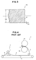
- FIG. 2 (c) shows a radial fragmentary cross-section of the outer peripheral surface portion of the rotating roll 22. As shown in FIG.
- the narrow grooves 24 have depths H24 of 0.1 to 0.5 mm (0.5 mm in this embodiment) and are V-shaped, e.g., have both inner side surfaces 24a perpendicular to each other in the embodiment.
- the narrow grooves 24 are formed by etching process after the outer peripheral surface of the rotating roll 22 is polished. Then, the etched peripheral surface of the rotating roll 22 is plated by chrome of which thickness is 0.03 mm.
- the smooth roll 23 has a diameter of 400 mm and an axial length of 950 mm like the rotating roll 22, and is rotated independently of the rotating roll 22 by a motor (not shown).
- the peripheral speed ratio of the rotating roll 22 to the smooth roll 23 is 1 to 0.818, namely, the peripheral speed of the rotating roll 22 is higher than that of the smooth roll 23.
- a reduction gear 26 drivably connected to motors 25 is provided above the smooth roll 23 in such a way as to be positioned on the inclined plane T and connected to a pressure shaft 27 which is connected to bearings of the smooth roll 23.
- the smooth roll 23 is controllably moved on the inclined plane T by the motor 25 through the reduction gear 26 and the pressure shaft 27, thereby regulating the feed clearance S between the rotating roll 22 and the smooth roll 23.
- the motor 25, the reduction gear 26 and the pressure shaft 27 collectively define regulating means 60 for regulating the feed clearance S between the rotating roll 22 and the smooth roll 23.
- the regulation of the clearance S makes it possible to control a feed thickness g of a feed rubber 28 which is fed to a compartment chamber 50 described below through an inlet port 50a thereof.
- a reference numeral 30 indicates a belt-shaped rubber material which is heated, i.e., warmed up by a warming up roll (not shown) and fed to the extruder 21 and allowed to pass through the feed clearance S between the rotating roll 22 and the smooth roll 23.
- a reference numeral 31 defines a stock guide plate placed between the rotating roll 22 and the smooth roll 23 and allowing the rubber material 30 to be guided to the feed clearance S between the rotating roll 22 and the smooth roll 23 so that the feed width of the feed rubber 28 extruded through the feed clearance S can be regulated to a predetermined level.
- the feed rubber 28 is able to have a preferred thickness and a width in response to a thickness and a width of a rubber sheet 38 extruded from the extruder 21 as described below so that the feed volume of the feed rubber 28 can be preferably controlled.
- a member 34 is placed in the vicinity of the rotating roll 22 in such a manner as to oppose to the stock guide plate 31 through the rotating roll 22, and has an arcuate inner surface 34a radially spaced apart from the outer peripheral surface 22a of the rotating roller 22.
- the arcuate inner surface 34a is recessed away from the rotating roller 22 and defines an arcuate compartment chamber 50 together with the outer peripheral surface 22a.
- the arcuate compartment chamber 50 has an inlet port 50a and an outlet port 50b spaced apart from each other in a rotational direction of the rotating roll 22. Furthermore, the arcuate compartment chamber 50 has a radial dimension gradually becoming smaller from the inlet port 50a toward the outlet port 50b.
- a die 35 is detachably attached to the member 34 in such a manner as to adjoin to the outlet port portion of the compartment chamber 50 and has an inner edge portion.
- the inner edge portion is radially spaced apart from the outer peripheral surface 22a of the rotating roll 22 and defines an extrusive clearance 36 together with the outer peripheral surface 22a.
- the inner edge portion of the die 35 is movable toward and away from the outer peripheral surface 22a of the rotating roll 22 so as to allow the extrusive clearance 36 to be controllable.
- the exchange of the die 35 makes it possible to change the dimension and the shape of the extrusive clearance 36, thereby making it possible to defining the extrusive clearances having various dimensions and shapes. If, for example, a die having an inner surface facing to the outer peripheral surface 22a is undulated, i.e., a so-called contour die is used, the extrusive clearance 36 has an undulated portion.
- the feed rubber 28 is fed into the arcuate compartment chamber 50 through the inlet port 50a thereof, the feed rubber 28 is moved toward the outlet port 50b thereof by the rotating roll 22, and then a rubber sheet 38 made of the feed rubber 28 and having a moderate high temperature is extruded from the arcuate compartment chamber 50 through the extrusive clearance 36. while the feed rubber 28 passes through the extrusive clearance 36, the elongated narrow grooves 24 are transferred to the feed rubber 28, thereby forming and elongated narrow protrusions 37 on one side surface portion of the feed rubber 28.
- the groove patterns as the rugged patterns of the rotating roll 22 are transferred to one side surface portion of the feed rubber 28 so that the rubber sheet 38 having the protrusion patterns as the rugged patterns formed on its one side surface portion is extruded from the extruder 21.
- the extruded rubber sheet 38 is guided to a conveyor belt 40 by a drawing-out roll 39 placed in the vicinity of the rotating roll 22.
- the rubber sheet 38 is 3.2 mm and 760mm in thickness D38 and width W38, respectively.
- the thickness D38 and the width W38 of the rubber sheet 38 are able to be changed by the positional regulation of the die 35.
- the shape of the rubber sheet 38 is able to be changed by the exchange of the die 35.
- the rotating roll 22 may be exchanged for a smooth roll or a roll having an undulated outer peripheral surface, i.e, a so-called contour roll. Accordingly, it is possible to change the thickness D38, the width W38 and the cross sectional shape of the rubber sheet 38 if necessary.
- the warmed up rubber material 30 is fed to the extruder 21 and allowed to pass through the feed clearance S between the rotating roll 22 and the smooth roll 23. Then, the feed width and the feed thickness of the rubber material 30 are controlled by the stock guide plate 31, the rotating roll 22 and the smooth roll 23, thereby feeding the feed rubber 28 having the preferred thickness and width into the compartment chamber 50 through the inlet port 50a thereof.
- the feed rubber 28 is kneaded together with the remaining rubber 28A in the arcuate compartment chamber 50, pressed and moved toward the outlet port 50b of the arcuate compartment chamber 50 by the rotating roll 22.
- the feed rubber 28 passes through the extrusive clearance 36, the feed rubber 28 is kept at a moderate high temperature.
- the narrow grooves 24 is transferred to the one side surface portion of the feed rubber sheet 28 so that the rubber sheet 38 with the protrusions 37 formed on its one side surface portion is extruded from the arcuate compartment chamber 50 through the extrusive clearance 36 by the rotation of the rotating roll 22.
- the feed rubber 28 fed into the compartment chamber 50 clings on the peripheral surface of the rotating roll 22, is kneaded and pressed together with the remaining rubber 28A in the compartment chamber 50 by the rotation of the rotating roll 22, and is moved to the extrusive clearance 36 adjoining to the outlet port 50b of the compartment chamber 50, i.e., the feed rubber 28 is moderately kneaded, pressed and moved toward the extrusive clearance 36 under continual uniform conditions. Accordingly, it is possible to prevent the feed rubber 28 from being cooled and to regularly extrude the rubber sheet 38 of a moderate high temperature.
- the rubber sheet 38 shaped like a sheet is stationarily extruded from the extruding clearance 36, but also the narrow protrusions 37 in response to the narrow grooves 24 are formed on the one side surface portion of the rubber sheet 38 as soon as the rubber in the chamber 50 is extruded and forms the sheet 38. Therefore, it is entirely unnecessary to conventionally determine and regulate the contact conditions between a ridge roll and a rubber sheet.
- the temperature of the rubber sheet 38 is so moderately high that the grooves 24 can be easily transferred to the rubber sheet 38, thereby making it possible to continually and uniformly keep the height and the shape of the protrusions 37 throughout the width of the rubber sheet 38 and to manufacture the rubber sheet 38 having the invariable and stable rugged patterns.
- the structure of the extruder 21 can be simple, namely, an apparatus for preparing a nonpatterned rubber sheet and an apparatus for forming patterns on one side surface portion of the sheet can be incorporated, so that the manufacturing process can be simple.
- the rotating roll 22 may be exchanged for the so-called contour roll.
Landscapes
- Engineering & Computer Science (AREA)
- Mechanical Engineering (AREA)
- Extrusion Moulding Of Plastics Or The Like (AREA)
- Tyre Moulding (AREA)
- Casting Or Compression Moulding Of Plastics Or The Like (AREA)
Applications Claiming Priority (2)
| Application Number | Priority Date | Filing Date | Title |
|---|---|---|---|
| JP03011841A JP3124561B2 (ja) | 1991-02-01 | 1991-02-01 | タイヤ用ゴムシート部材 |
| JP11841/91 | 1991-02-01 |
Publications (2)
| Publication Number | Publication Date |
|---|---|
| EP0497582A2 true EP0497582A2 (fr) | 1992-08-05 |
| EP0497582A3 EP0497582A3 (en) | 1993-03-31 |
Family
ID=11788956
Family Applications (1)
| Application Number | Title | Priority Date | Filing Date |
|---|---|---|---|
| EP19920300770 Withdrawn EP0497582A3 (en) | 1991-02-01 | 1992-01-29 | Method of manufacturing rubber sheet with rugged patterns formed on its one side surface portion |
Country Status (3)
| Country | Link |
|---|---|
| US (1) | US5234647A (fr) |
| EP (1) | EP0497582A3 (fr) |
| JP (1) | JP3124561B2 (fr) |
Cited By (2)
| Publication number | Priority date | Publication date | Assignee | Title |
|---|---|---|---|---|
| EP3501780A1 (fr) * | 2017-12-19 | 2019-06-26 | The Goodyear Tire & Rubber Company | Procédé et appareil de fabrication de bande de caoutchouc |
| CN110001099A (zh) * | 2017-12-19 | 2019-07-12 | 固特异轮胎和橡胶公司 | 用于形成橡胶增强部件的方法和设备 |
Families Citing this family (9)
| Publication number | Priority date | Publication date | Assignee | Title |
|---|---|---|---|---|
| FR2700291A1 (fr) * | 1993-01-08 | 1994-07-13 | Michelin & Cie | Appareil d'extrusion et procédé d'extrusion pour mélanges de caoutchouc cru. |
| JP3204842B2 (ja) | 1994-06-07 | 2001-09-04 | 富士通株式会社 | Cadシステムにおける編集装置および編集方法 |
| EP0753391B1 (fr) * | 1995-07-13 | 2001-09-19 | Sumitomo Rubber Industries Ltd. | Appareil d'extrusion pour élastomère |
| JP4212365B2 (ja) * | 2003-01-14 | 2009-01-21 | 株式会社ブリヂストン | タイヤ構成部材の形成方法 |
| US7694707B2 (en) | 2005-12-20 | 2010-04-13 | The Goodyear Tire & Rubber Company | Tire with integral foamed noise damper |
| US20070187863A1 (en) * | 2006-02-15 | 2007-08-16 | Hsin Yung Chien Co., Ltd. | Ultra-wide, anti-slippery rubber sheet and molding machine and method of fabricating the same |
| JP4978646B2 (ja) * | 2009-03-13 | 2012-07-18 | 横浜ゴム株式会社 | 空気入りタイヤの製造方法 |
| FR2964591B1 (fr) * | 2010-09-10 | 2014-02-14 | Michelin Soc Tech | Procede de fabrication d'une ebauche de pneumatique au moyen d'une bandelette |
| CN109130049B (zh) * | 2018-09-07 | 2019-07-12 | 深圳市生利科创包装制品有限公司 | 一种橡胶加工系统 |
Family Cites Families (14)
| Publication number | Priority date | Publication date | Assignee | Title |
|---|---|---|---|---|
| US2382177A (en) * | 1941-10-15 | 1945-08-14 | Goodrich Co B F | Apparatus for making composite strips |
| BE500474A (fr) * | 1950-01-11 | 1900-01-01 | ||
| US2842796A (en) * | 1954-08-31 | 1958-07-15 | Us Rubber Co | Rubber shaping and vulcanizing apparatus |
| US2892212A (en) * | 1955-04-05 | 1959-06-30 | Us Rubber Co | Extrusion apparatus |
| US2976565A (en) * | 1958-05-23 | 1961-03-28 | Us Rubber Co | Mixing apparatus and method |
| DE1085330B (de) * | 1959-03-18 | 1960-07-14 | Norddeutsche Seekabelwerke Ag | Verfahren und Vorrichtung zur Herstellung von Netzen aus thermoplastischem Kunststoff |
| FR1258370A (fr) * | 1960-03-02 | 1961-04-14 | Rhone Poulenc Sa | Procédé de fabrication de dentelles et articles analogues en matière plastique |
| US3143155A (en) * | 1961-05-29 | 1964-08-04 | Firestone Tire & Rubber Co | Tire |
| US3533896A (en) * | 1967-03-27 | 1970-10-13 | Du Pont | Anchoring device of thermoplastic resin |
| US3999914A (en) * | 1971-05-14 | 1976-12-28 | Breco Kunststoffverarbeitungs-Gmbh & Co. Kg | Device for producing in a continuous manner reinforced profile belts from extruded material |
| US3871810A (en) * | 1972-11-20 | 1975-03-18 | Uniroyal Inc | Extruder and roller-die combination |
| GB2134428B (en) * | 1983-02-03 | 1987-06-17 | Metal Box Plc | Continuous extrusion of metals |
| JPS60131219A (ja) * | 1983-12-21 | 1985-07-12 | Bridgestone Corp | ゴム押出し成形方法 |
| US5030079A (en) * | 1989-10-27 | 1991-07-09 | The Goodyear Tire & Rubber Company | Roller die extrusion and calendering apparatus |
-
1991
- 1991-02-01 JP JP03011841A patent/JP3124561B2/ja not_active Expired - Lifetime
-
1992
- 1992-01-24 US US07/825,086 patent/US5234647A/en not_active Expired - Fee Related
- 1992-01-29 EP EP19920300770 patent/EP0497582A3/en not_active Withdrawn
Cited By (3)
| Publication number | Priority date | Publication date | Assignee | Title |
|---|---|---|---|---|
| EP3501780A1 (fr) * | 2017-12-19 | 2019-06-26 | The Goodyear Tire & Rubber Company | Procédé et appareil de fabrication de bande de caoutchouc |
| CN110001099A (zh) * | 2017-12-19 | 2019-07-12 | 固特异轮胎和橡胶公司 | 用于形成橡胶增强部件的方法和设备 |
| CN110001097A (zh) * | 2017-12-19 | 2019-07-12 | 固特异轮胎和橡胶公司 | 条带层压方法和设备 |
Also Published As
| Publication number | Publication date |
|---|---|
| US5234647A (en) | 1993-08-10 |
| JP3124561B2 (ja) | 2001-01-15 |
| JPH04246524A (ja) | 1992-09-02 |
| EP0497582A3 (en) | 1993-03-31 |
Similar Documents
| Publication | Publication Date | Title |
|---|---|---|
| JP3954195B2 (ja) | タイヤ成型装置およびそれを用いたタイヤ成型方法 | |
| EP1279486B1 (fr) | Procédé de fabrication d'un article moulé en caoutchouc | |
| US5234647A (en) | Method of manufacturing rubber sheet with rugged patterns formed on its one side surface portion | |
| US5030079A (en) | Roller die extrusion and calendering apparatus | |
| CA2045764C (fr) | Procede et dispositif de fabrication de feuilles de caoutchouc armees de cordes | |
| EP2033763B1 (fr) | Procédé de fabrication d'un élément en caoutchouc mince, rouleau en caoutchouc, et procédé de roulage d'un caoutchouc | |
| JPH0794155B2 (ja) | 支持体上にゴム材料を順次取付けてタイヤを製造する方法および装置 | |
| CZ2001209A3 (cs) | Způsob výroby pneumatiky | |
| US20210023804A1 (en) | Process and apparatus for building tyres | |
| US7622013B2 (en) | Tire manufacturing method, cover rubber stamping device used therefore, tire, as well as rubber sheet member stamping method, and device | |
| JP2002514141A (ja) | ファスナー製品等の連続成形及びそれによって製造させる製品 | |
| EP0485127A1 (fr) | Procédé et dispositif pour la fabrication d'une structure en caoutchouc non-vulcanisé | |
| US20060090836A1 (en) | Method and apparatus for manufacturing elastomeric material components of a tyre for vehicle wheels | |
| DE69527040T2 (de) | Verfahren und Vorrichtung zum Herstellen eines Laminats und zum Aufbau einer Reifenkarkasse aus einer Anordnung von Reifenbestandteilen | |
| EP2049324B1 (fr) | Procédé et appareil de fabrication de pneus | |
| JP2000108222A (ja) | ストリップワインド成形機 | |
| US7052568B2 (en) | Tire retreading method | |
| US4565514A (en) | Apparatus for shaping in a calibrated way a rubber pre-extruded profiled member for regenerating tires and the like | |
| EP1082207B1 (fr) | Procede et appareil de mise en forme de composants pour pneumatiques | |
| JPH0747617A (ja) | 空気入りタイヤの製造方法及び空気入りタイヤ | |
| EP1849625A1 (fr) | Pneumatique, structure d'agencement de pneumatique, et procede de fabrication correspondant | |
| WO1999004960A1 (fr) | Ameliorations dans la fabrication de pneumatiques | |
| MXPA00011293A (en) | A method and apparatus for forming tire components | |
| JP2000071310A (ja) | 押出成形板の製造装置 | |
| JPH0729288B2 (ja) | セメント瓦の製造方法 |
Legal Events
| Date | Code | Title | Description |
|---|---|---|---|
| PUAI | Public reference made under article 153(3) epc to a published international application that has entered the european phase |
Free format text: ORIGINAL CODE: 0009012 |
|
| AK | Designated contracting states |
Kind code of ref document: A2 Designated state(s): DE ES FR GB IT |
|
| PUAL | Search report despatched |
Free format text: ORIGINAL CODE: 0009013 |
|
| AK | Designated contracting states |
Kind code of ref document: A3 Designated state(s): DE ES FR GB IT |
|
| 17P | Request for examination filed |
Effective date: 19930604 |
|
| 17Q | First examination report despatched |
Effective date: 19940624 |
|
| 18D | Application deemed to be withdrawn |
Effective date: 19941105 |