EP0497625B1 - Stossdämpfer - Google Patents
Stossdämpfer Download PDFInfo
- Publication number
- EP0497625B1 EP0497625B1 EP92300865A EP92300865A EP0497625B1 EP 0497625 B1 EP0497625 B1 EP 0497625B1 EP 92300865 A EP92300865 A EP 92300865A EP 92300865 A EP92300865 A EP 92300865A EP 0497625 B1 EP0497625 B1 EP 0497625B1
- Authority
- EP
- European Patent Office
- Prior art keywords
- outer shell
- cylinder
- piston
- shock absorber
- bottomed cylinder
- Prior art date
- Legal status (The legal status is an assumption and is not a legal conclusion. Google has not performed a legal analysis and makes no representation as to the accuracy of the status listed.)
- Expired - Lifetime
Links
Images


Classifications
-
- B—PERFORMING OPERATIONS; TRANSPORTING
- B60—VEHICLES IN GENERAL
- B60G—VEHICLE SUSPENSION ARRANGEMENTS
- B60G13/00—Resilient suspensions characterised by arrangement, location or type of vibration dampers
- B60G13/001—Arrangements for attachment of dampers
- B60G13/005—Arrangements for attachment of dampers characterised by the mounting on the axle or suspension arm of the damper unit
- B60G13/006—Arrangements for attachment of dampers characterised by the mounting on the axle or suspension arm of the damper unit on the stub axle
-
- B—PERFORMING OPERATIONS; TRANSPORTING
- B60—VEHICLES IN GENERAL
- B60G—VEHICLE SUSPENSION ARRANGEMENTS
- B60G13/00—Resilient suspensions characterised by arrangement, location or type of vibration dampers
-
- F—MECHANICAL ENGINEERING; LIGHTING; HEATING; WEAPONS; BLASTING
- F16—ENGINEERING ELEMENTS AND UNITS; GENERAL MEASURES FOR PRODUCING AND MAINTAINING EFFECTIVE FUNCTIONING OF MACHINES OR INSTALLATIONS; THERMAL INSULATION IN GENERAL
- F16F—SPRINGS; SHOCK-ABSORBERS; MEANS FOR DAMPING VIBRATION
- F16F9/00—Springs, vibration-dampers, shock-absorbers, or similarly-constructed movement-dampers using a fluid or the equivalent as damping medium
- F16F9/32—Details
- F16F9/3207—Constructional features
- F16F9/3235—Constructional features of cylinders
-
- B—PERFORMING OPERATIONS; TRANSPORTING
- B60—VEHICLES IN GENERAL
- B60G—VEHICLE SUSPENSION ARRANGEMENTS
- B60G2202/00—Indexing codes relating to the type of spring, damper or actuator
- B60G2202/30—Spring/Damper and/or actuator Units
- B60G2202/31—Spring/Damper and/or actuator Units with the spring arranged around the damper, e.g. MacPherson strut
- B60G2202/312—The spring being a wound spring
-
- B—PERFORMING OPERATIONS; TRANSPORTING
- B60—VEHICLES IN GENERAL
- B60G—VEHICLE SUSPENSION ARRANGEMENTS
- B60G2204/00—Indexing codes related to suspensions per se or to auxiliary parts
- B60G2204/10—Mounting of suspension elements
- B60G2204/12—Mounting of springs or dampers
- B60G2204/129—Damper mount on wheel suspension or knuckle
-
- B—PERFORMING OPERATIONS; TRANSPORTING
- B60—VEHICLES IN GENERAL
- B60G—VEHICLE SUSPENSION ARRANGEMENTS
- B60G2204/00—Indexing codes related to suspensions per se or to auxiliary parts
- B60G2204/40—Auxiliary suspension parts; Adjustment of suspensions
- B60G2204/43—Fittings, brackets or knuckles
- B60G2204/4304—Bracket for lower cylinder mount of McPherson strut
-
- B—PERFORMING OPERATIONS; TRANSPORTING
- B60—VEHICLES IN GENERAL
- B60G—VEHICLE SUSPENSION ARRANGEMENTS
- B60G2206/00—Indexing codes related to the manufacturing of suspensions: constructional features, the materials used, procedures or tools
- B60G2206/01—Constructional features of suspension elements, e.g. arms, dampers, springs
- B60G2206/40—Constructional features of dampers and/or springs
Definitions
- This invention relates to an outer shell structure of a strut type shock absorber disposed between the body of a vehicle such as a four-wheeled vehicle and an axle thereof to damp vibrations from the surface of a road.
- shock absorber for reducing the transfer of vibration to the vehicle body to ensure stable running of the vehicle independently of running conditions, changes in the state of a road surface, etc.
- Shock absorbers of this type there are known, for example, those disclosed in Japanese Utility Model Publication No. 32035/1983, Japanese Utility Model Laid Open No. 16194/1980, U.S. Patent Application Serial No. 401501 (specification and drawings) and European Patent Application No. 81107940 (specification and drawings).
- the conventional shock absorbers disclosed in Japanese Utility Model Publication No. 32035/1983, for example, has the structure shown in Fig. 3 attached hereto.
- the reference numeral 1 denotes a cylinder
- the numeral 2 denotes a piston provided with a damping force generating mechanism which piston partitions the interior of the cylinder 1 into a rod-side chamber 3 and a piston-side chamber 4
- numeral 5 denotes a piston rod
- numeral 6 denotes an outer shell which encloses the outside of the cylinder 1 to define a reservoir chamber 7
- numeral 8 denotes a base valve for imparting a damping force to a hydraulic oil flowing between the reservoir chamber 7 and the piston-side chamber 4
- numeral 9 denotes a bearing portion which closes the upper ends of the rod-side chamber 3 and the reservoir chamber 7 and locates the piston rod 5 for hermetically sealed entrance and exit of the piston rod with respect to the interior of the cylinder 1.
- numeral 10 denotes a lower cap provided at an end of the cylinder 1 so as to enclose the base valve 8
- numeral 11 denotes a knuckle bracket which supports the outer periphery of the lower end of the outer shell 6 and which is mounted on the axle side, the knuckle bracket 11 and the lower cap 10 being integrally connected with each other through a lower weld portion 12.
- Numeral 13 denotes a spring guide and numeral 14 denotes a seam weld portion.
- the outer shell 6 In order to obtain an optimum strength, i.e., strength against a bending moment load, of the portion of the outer shell 6 opposed to the knuckle bracket 11, despite a light weight thereof, the outer shell 6 is smaller in its thickness on the side of the seam weld portion 14 and is sufficiently large in its thickness on the lower weld portion 12 side, according to a bending moment load distribution. As a whole, the outer shell is formed as a tapered pipe to attain the reduction in weight thereof.
- the conventional shock absorber is constructed as above, it is necessary to fabricate the outer shell 6 as a tapered pipe like the above or, if necessary, as a stepped pipe by drawing, thus requiring the use of special die and plug, resulting in that not only large-scaled equipment and power and plant investment are required but also the processing time and cost are increased.
- a shock absorber including a piston provided with a damping force generating mechanism, said piston partitioning the interior of a cylinder into a rod-side chamber and a piston side chamber; a piston rod having said piston secured thereto, said piston rod being moveable into and out of said cylinder; a base valve provided in an open end of said piston side chamber of the cylinder; and an outer shell structure comprising an outer shell enclosing the outside of said cylinder to form a reservoir chamber, whereby the shock absorber includes a bottomed cylinder fitted in the lower end portion of the outer shell along the inner periphery thereof, said bottomed cylinder having a cylindrical portion which co-operates with the outer shell and which has a predetermined axial length, said bottomed cylinder being welded to said outer shell, said outer shell being thin walled and of a generally constant wall thickness.
- a shock absorber including a piston provided with a damping force generating mechanism, said piston partitioning the interior of a cylinder into a rod-side chamber and a piston-side chamber; a piston rod having said piston secured thereto, said piston rod being moveable into and out of said cylinder; a base valve provided in an open end of said piston-side chamber of the cylinder; and an outer shell structure comprising an outer shell enclosing the outside of said cylinder to form a reservoir chamber;
- the shock absorber including a bottomed cylinder fitted in the lower end portion of the outer shell along the inner periphery thereof, said bottomed cylinder having a cylindrical portion which co-operates with the shell and which has a predetermined axial length, said outer shell being thin walled and of a constant wall thickness, characterised in that the outer shell structure includes a knuckle bracket for supporting the outer periphery of an end portion of said outer shell remote from the piston; and in that the bottomed cylinder is welded to
- small wall thickness and “thin walled” as used herein is meant a wall thickness which is less than that of the bottomed cylinder, or of the wall thickness of a corresponding component in the prior art device.
- a strut type shock absorber advantageously having an outer shell formed using a standard, inexpensive, thin-walled pipe of a certain thickness.
- shock absorber can be arranged so that the bottomed cylinder, specifically the cylindrical portion thereof, bears a maximum bending moment load.
- a strut type shock absorber which, despite being light in weight, can afford an optimum strength according to a bending moment load distribution.
- a strut type shock absorber which is easy to manufacture and which is capable of decreasing the manufacturing time and cost.
- the bottomed cylinder used in the above construction of the present invention also serves as the conventional lower cap which seals a hydraulic oil within the cylinder, and it is fitted in the outer shell along the inner periphery of a lower end portion of the outer shell which is thin-walled and then welded to the outer shell together with the knuckle bracket. Therefore, the end portion of the outer shell where a maximum bending moment load is generated can be reinforced in a simple construction easily and inexpensively.
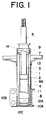
- the reference numeral 6A denotes an outer shell formed using an ordinary thin-walled pipe and having a wall thickness which is constant throughout the overall length thereof
- the numeral 10A denotes a bottomed cylinder fitted in the outer shell 6A along the inner periphery of an end portion of the outer shell.
- the bottomed cylinder extends over a predetermined axial length of the outer shell and is welded integrally with the outer shell 6A and a knuckle bracket 11.
- the bottomed cylinder 10A comprises a cylindrical portion 10B which bears a maximum bending moment load in cooperation with the lower end portion of the outer shell 6A, and a bottom 10C used as a lower cap which seals the lower end of a cylinder 1.
- Numeral 12A denotes a weld portion.
- the cylindrical portion 10B of the bottomed cylinder 10A is also constant in its wall thickness.
- Other constructional portions which are the same as in Fig. 3 are indicated by the same reference numerals as in Fig. 3 and repeated explanations thereof will be omitted.
- the shock absorber of this embodiment like the one described above in connection with the prior art, generates a damping force during the extension stroke and compression stroke of a piston rod 5.
- the outer shell 6A is thin-walled throughout the overall length thereof to an extent capable of withstanding a predetermined bending moment load.
- the bottomed cylinder 10A is fitted in an end portion of the outer shell 6A on the inner periphery side of the same shell, for example by press-fitting and is then connected integrally with the outer shell 6A and the knuckle bracket 11 by welding, whereby the strength of the outer shell can be made sufficient, or optimal, despite the light weight thereof.
- the outer shell 6A is constituted by a commercially available thin-walled cylinder, it is light-weight, inexpensive and obtainable easily, so the shock absorber can be manufactured using an existing inexpensive welding apparatus without using any expensive equipment. Besides, since the assembly can be done merely by fitting and welding, the mounting efficiency can be improved and the quality can be made reliable.
- FIG. 2 there is illustrated another example of a bottomed cylinder.
- the cylindrical wall portion of this bottomed cylinder has cutouts, unlike the bottomed cylinder shown in Fig. 1.
- a bending moment load acts in the direction X-X passing through the axis including a knuckle mounting bracket of the knuckle bracket 11.
- a cylindrical portion 10B′ in the X-X direction is allowed to remain, while a cylindrical portion in the direction Y-Y passing through the axis is cut out to form cutout portions 10b, 10b.
- the bottomed cylinder not only reinforces the outer shell and the knuckle bracket but also serves as a lower cap of the cylinder, and thus two functions can be attained by a single member.
Landscapes
- Engineering & Computer Science (AREA)
- Mechanical Engineering (AREA)
- General Engineering & Computer Science (AREA)
- Fluid-Damping Devices (AREA)
- Television Signal Processing For Recording (AREA)
- Signal Processing For Digital Recording And Reproducing (AREA)
- Vehicle Body Suspensions (AREA)
Claims (5)
- Stoßdämpfer mit
einem Kolben (2), der mit einem Dämpfungskraft erzeugenden Mechanismus versehen ist, wobei dieser Kolben das Innere eines Zylinders (1) in eine Stangenseitenkammer (3) und eine Kolbenseitenkammer (4) teilt,
einer Kolbenstange (5), an der der Kolben (2) befestigt ist, wobei die Kolbenstange (5) in den Zylinder (1) und aus ihm bewegbar ist,
einem Basisventil (8), das in einem offenen Ende der Kolbenseitenkammer des Zylinders vorgesehen ist, und
einer Außengehäusestruktur, die ein Außengehäuse (6A) umfaßt, welches die Außenseite des Zylinders (1) unter Bildung einer Speicherkammer (7) einschließt, wobei der Stoßdämpfer einen mit Boden versehenen Zylinder (10A) einschließt, der in dem unteren Endabschnitt des Außengehäuses (6A) entlang dem inneren Umfang desselben eingepaßt ist, der mit Boden versehene Zylinder (10A) einen zylindrischen Abschnitt (10B) hat, welcher mit dem Gehäuse (6A) zusammenarbeitet und welcher eine vorbestimmte Axiallänge hat, und das Außengehäuse (6A) dünnwandig ist und eine konstante Wanddicke besitzt,
dadurch gekennzeichnet, daß die Außengehäusestruktur eine Verbindungsstütze (11) zur Unterstützung des Außenumfanges eines Endabschnittes des Außengehäuses (6A) entfernt von dem Kolben (2) einschließt und daß der mit Boden versehene Zylinder (10A) mit dem Außengehäuse und der Verbindungsstütze verschweißt ist. - Stoßdämpfer nach Anspruch 1, dadurch gekennzeichnet, daß der untere Endabschnitt des Außgenhäuses (6A), wo eine maximale Biegemomentbelastung erzeugt wird, eine Doppelrohrstruktur hat, die ein dünnwandiges Rohr mit konstanter Wanddicke und einen zylindrischen Abschnitt (10B), welcher in dieses Rohr eingepaßt ist und eine vorbestimmte Axiallänge besitzt, umfaßt.
- Stoßdämpfer nach Anspruch 1, dadurch gekennzeichnet, daß der zylindrische Abschnitt (10B) des mit Boden versehenen Zylinders in den unteren Endabschnitt des Außengehäuses (6A) entlang dem Innenumfang desselben eingepaßt ist und der Boden (10C) des mit Boden versehenen Zylinders (10A) als eine untere Kappe an einem unteren Ende des Zylinders wirkt.
- Stoßdämpfer nach Anspruch 1, dadurch gekennzeichnet, daß der Innenumfang eines unteren Endabschnittes der Verbindungsstütze (11), das untere Ende des Außengehäuses (6A) und der Außenumfang des Bodens (10C) des mit Boden versehenen Zylinders (10A) durch Schweißen miteinander verbunden sind.
- Stoßdämpfer nach einem der Ansprüche 1 bis 4, dadurch gekennzeichnet, daß der mit Boden versehene Zylinder (10A) eine oder mehrere Vertiefungen oder Ausschnitte (10B) hat, die in seiner Wand ausgebildet sind, wobei die Vertiefungen oder Ausschnitte (10B) den Bereichen des mit Boden versehenen Zylinders (10A) entsprechen, die kleinen Biegespannungen in bezug auf den Rest des mit Boden versehenen Zylinders (10A) ausgesetzt sind.
Applications Claiming Priority (2)
| Application Number | Priority Date | Filing Date | Title |
|---|---|---|---|
| JP919205A JPH04252618A (ja) | 1991-01-29 | 1991-01-29 | ディジタルデータのデコーダ |
| JP9205/91 | 1991-01-31 |
Publications (2)
| Publication Number | Publication Date |
|---|---|
| EP0497625A1 EP0497625A1 (de) | 1992-08-05 |
| EP0497625B1 true EP0497625B1 (de) | 1995-07-26 |
Family
ID=11713977
Family Applications (1)
| Application Number | Title | Priority Date | Filing Date |
|---|---|---|---|
| EP92300865A Expired - Lifetime EP0497625B1 (de) | 1991-01-29 | 1992-01-31 | Stossdämpfer |
Country Status (4)
| Country | Link |
|---|---|
| EP (1) | EP0497625B1 (de) |
| JP (1) | JPH04252618A (de) |
| KR (1) | KR950003212B1 (de) |
| DE (1) | DE69203621T2 (de) |
Families Citing this family (3)
| Publication number | Priority date | Publication date | Assignee | Title |
|---|---|---|---|---|
| DE102011015021C5 (de) * | 2011-03-25 | 2015-12-17 | Audi Ag | Teleskop-Stoßdämpfer |
| DE102013109370B4 (de) | 2013-03-29 | 2024-02-01 | Hitachi Astemo, Ltd. | Hydraulikstoßdämpfungsvorrichtung |
| DE102015116182A1 (de) | 2015-09-24 | 2017-03-30 | Thyssenkrupp Ag | Schwingungsdämpfer |
Family Cites Families (9)
| Publication number | Priority date | Publication date | Assignee | Title |
|---|---|---|---|---|
| GB1232236A (de) * | 1968-05-25 | 1971-05-19 | ||
| GB1516836A (en) * | 1974-08-22 | 1978-07-05 | Woodhead Ltd J | Hydraulic shock absorbers |
| AR205418A1 (es) * | 1975-01-20 | 1976-04-30 | Monroe Auto Equipment Co | Una construccion de piston de amortiguador |
| GB1599168A (en) * | 1977-12-23 | 1981-09-30 | Woodhead Ltd Jonas | Shock absorbers |
| IT1107119B (it) * | 1978-03-14 | 1985-11-18 | Iao Industrie Riunite Spa | Perfezionamenti neli ammortizzatori idraulici del tipo telescopico |
| US4460073A (en) * | 1980-02-04 | 1984-07-17 | Maremont Corporation | Shock absorber with improved back check and anti-dump valve mechanisms |
| JPS56149149U (de) * | 1980-04-09 | 1981-11-09 | ||
| JPS612832Y2 (de) * | 1980-09-12 | 1986-01-29 | ||
| DE3337798A1 (de) * | 1983-10-18 | 1985-05-02 | Boge Gmbh, 5208 Eitorf | Hydraulischer zweirohr-schwingungsdaempfer |
-
1991
- 1991-01-29 JP JP919205A patent/JPH04252618A/ja active Pending
-
1992
- 1992-01-24 KR KR1019920001039A patent/KR950003212B1/ko not_active Expired - Fee Related
- 1992-01-31 EP EP92300865A patent/EP0497625B1/de not_active Expired - Lifetime
- 1992-01-31 DE DE69203621T patent/DE69203621T2/de not_active Expired - Fee Related
Also Published As
| Publication number | Publication date |
|---|---|
| DE69203621T2 (de) | 1996-01-11 |
| EP0497625A1 (de) | 1992-08-05 |
| KR920014649A (ko) | 1992-08-25 |
| DE69203621D1 (de) | 1995-08-31 |
| KR950003212B1 (ko) | 1995-04-06 |
| JPH04252618A (ja) | 1992-09-08 |
Similar Documents
| Publication | Publication Date | Title |
|---|---|---|
| US5477947A (en) | Automobile shock absorber with frequency-selective action | |
| US7413064B2 (en) | Front fork | |
| WO1997010962A1 (en) | Suspension strut assembly | |
| US5244064A (en) | Shock absorber | |
| CN112539241A (zh) | 用于阻尼器的基座构件 | |
| EP1110768B1 (de) | Fahrzeugaufhängungsvorrichtung | |
| US6220408B1 (en) | Spring and damper unit with external storage device | |
| JPH09105437A (ja) | ショックアブソーバ | |
| EP0497625A1 (de) | Stossdämpfer | |
| JPH1182590A (ja) | 油圧緩衝器 | |
| JP7182495B6 (ja) | シリンダ装置 | |
| JP4137540B2 (ja) | 車両の油圧緩衝装置 | |
| JP2005155793A (ja) | 油圧緩衝器 | |
| JP6637806B2 (ja) | 懸架装置 | |
| JP2001330076A (ja) | 倒立型油圧緩衝器 | |
| JP2929215B2 (ja) | 油圧緩衝器 | |
| JPH082510Y2 (ja) | フロントフオーク | |
| JPH059546Y2 (de) | ||
| JP7443631B1 (ja) | 車高調整装置 | |
| JP3727089B2 (ja) | 倒立型フロントフォーク | |
| JPS5922356Y2 (ja) | 油圧緩衝器 | |
| JPS59100076A (ja) | オ−トバイ用前輪ばね懸架装置 | |
| JP2000074122A (ja) | 車両用緩衝器 | |
| JP3573169B2 (ja) | フロントフォーク | |
| JPH055300Y2 (de) |
Legal Events
| Date | Code | Title | Description |
|---|---|---|---|
| PUAI | Public reference made under article 153(3) epc to a published international application that has entered the european phase |
Free format text: ORIGINAL CODE: 0009012 |
|
| AK | Designated contracting states |
Kind code of ref document: A1 Designated state(s): BE DE FR GB IT |
|
| 17P | Request for examination filed |
Effective date: 19930123 |
|
| 17Q | First examination report despatched |
Effective date: 19940325 |
|
| GRAA | (expected) grant |
Free format text: ORIGINAL CODE: 0009210 |
|
| AK | Designated contracting states |
Kind code of ref document: B1 Designated state(s): BE DE FR GB IT |
|
| REF | Corresponds to: |
Ref document number: 69203621 Country of ref document: DE Date of ref document: 19950831 |
|
| ET | Fr: translation filed | ||
| ITF | It: translation for a ep patent filed | ||
| PLBE | No opposition filed within time limit |
Free format text: ORIGINAL CODE: 0009261 |
|
| 26N | No opposition filed | ||
| REG | Reference to a national code |
Ref country code: GB Ref legal event code: IF02 |
|
| PGFP | Annual fee paid to national office [announced via postgrant information from national office to epo] |
Ref country code: FR Payment date: 20040108 Year of fee payment: 13 |
|
| PGFP | Annual fee paid to national office [announced via postgrant information from national office to epo] |
Ref country code: GB Payment date: 20040128 Year of fee payment: 13 |
|
| PGFP | Annual fee paid to national office [announced via postgrant information from national office to epo] |
Ref country code: BE Payment date: 20040409 Year of fee payment: 13 |
|
| PG25 | Lapsed in a contracting state [announced via postgrant information from national office to epo] |
Ref country code: IT Free format text: LAPSE BECAUSE OF NON-PAYMENT OF DUE FEES;WARNING: LAPSES OF ITALIAN PATENTS WITH EFFECTIVE DATE BEFORE 2007 MAY HAVE OCCURRED AT ANY TIME BEFORE 2007. THE CORRECT EFFECTIVE DATE MAY BE DIFFERENT FROM THE ONE RECORDED. Effective date: 20050131 Ref country code: GB Free format text: LAPSE BECAUSE OF NON-PAYMENT OF DUE FEES Effective date: 20050131 Ref country code: BE Free format text: LAPSE BECAUSE OF NON-PAYMENT OF DUE FEES Effective date: 20050131 |
|
| BERE | Be: lapsed |
Owner name: *KAYABA KOGYO K.K. Effective date: 20050131 |
|
| GBPC | Gb: european patent ceased through non-payment of renewal fee |
Effective date: 20050131 |
|
| PG25 | Lapsed in a contracting state [announced via postgrant information from national office to epo] |
Ref country code: FR Free format text: LAPSE BECAUSE OF NON-PAYMENT OF DUE FEES Effective date: 20050930 |
|
| REG | Reference to a national code |
Ref country code: FR Ref legal event code: ST |
|
| PGFP | Annual fee paid to national office [announced via postgrant information from national office to epo] |
Ref country code: DE Payment date: 20060126 Year of fee payment: 15 |
|
| PG25 | Lapsed in a contracting state [announced via postgrant information from national office to epo] |
Ref country code: DE Free format text: LAPSE BECAUSE OF NON-PAYMENT OF DUE FEES Effective date: 20070801 |
|
| BERE | Be: lapsed |
Owner name: *KAYABA KOGYO K.K. Effective date: 20050131 |