EP0498018A1 - Capteur d'accélération - Google Patents
Capteur d'accélération Download PDFInfo
- Publication number
- EP0498018A1 EP0498018A1 EP91101789A EP91101789A EP0498018A1 EP 0498018 A1 EP0498018 A1 EP 0498018A1 EP 91101789 A EP91101789 A EP 91101789A EP 91101789 A EP91101789 A EP 91101789A EP 0498018 A1 EP0498018 A1 EP 0498018A1
- Authority
- EP
- European Patent Office
- Prior art keywords
- magnetic
- permanent magnet
- movable
- movable permanent
- acceleration sensor
- Prior art date
- Legal status (The legal status is an assumption and is not a legal conclusion. Google has not performed a legal analysis and makes no representation as to the accuracy of the status listed.)
- Withdrawn
Links
- 230000001133 acceleration Effects 0.000 title claims abstract description 90
- 239000000696 magnetic material Substances 0.000 claims abstract description 9
- 230000004044 response Effects 0.000 claims abstract description 9
- 239000011553 magnetic fluid Substances 0.000 claims description 22
- 230000035939 shock Effects 0.000 abstract description 6
- BGPVFRJUHWVFKM-UHFFFAOYSA-N N1=C2C=CC=CC2=[N+]([O-])C1(CC1)CCC21N=C1C=CC=CC1=[N+]2[O-] Chemical compound N1=C2C=CC=CC2=[N+]([O-])C1(CC1)CCC21N=C1C=CC=CC1=[N+]2[O-] BGPVFRJUHWVFKM-UHFFFAOYSA-N 0.000 description 26
- 230000004048 modification Effects 0.000 description 20
- 238000012986 modification Methods 0.000 description 20
- 238000010276 construction Methods 0.000 description 13
- 238000001514 detection method Methods 0.000 description 8
- 230000000694 effects Effects 0.000 description 8
- 239000011521 glass Substances 0.000 description 6
- 230000035945 sensitivity Effects 0.000 description 4
- 230000004907 flux Effects 0.000 description 3
- XKRFYHLGVUSROY-UHFFFAOYSA-N Argon Chemical compound [Ar] XKRFYHLGVUSROY-UHFFFAOYSA-N 0.000 description 2
- IJGRMHOSHXDMSA-UHFFFAOYSA-N Atomic nitrogen Chemical compound N#N IJGRMHOSHXDMSA-UHFFFAOYSA-N 0.000 description 2
- 239000000463 material Substances 0.000 description 2
- 230000007246 mechanism Effects 0.000 description 2
- 239000002184 metal Substances 0.000 description 2
- 229910052751 metal Inorganic materials 0.000 description 2
- 239000011347 resin Substances 0.000 description 2
- 229920005989 resin Polymers 0.000 description 2
- 125000006850 spacer group Chemical group 0.000 description 2
- 229910052786 argon Inorganic materials 0.000 description 1
- 239000003990 capacitor Substances 0.000 description 1
- 230000008859 change Effects 0.000 description 1
- 238000010586 diagram Methods 0.000 description 1
- 238000006073 displacement reaction Methods 0.000 description 1
- 230000002708 enhancing effect Effects 0.000 description 1
- 239000007789 gas Substances 0.000 description 1
- 239000011261 inert gas Substances 0.000 description 1
- 230000001050 lubricating effect Effects 0.000 description 1
- 238000000034 method Methods 0.000 description 1
- 238000000465 moulding Methods 0.000 description 1
- 229910052757 nitrogen Inorganic materials 0.000 description 1
- 230000000149 penetrating effect Effects 0.000 description 1
- 230000008569 process Effects 0.000 description 1
- 230000001737 promoting effect Effects 0.000 description 1
- 238000007711 solidification Methods 0.000 description 1
- 230000008023 solidification Effects 0.000 description 1
- 229910000859 α-Fe Inorganic materials 0.000 description 1
Images






Classifications
-
- G—PHYSICS
- G01—MEASURING; TESTING
- G01P—MEASURING LINEAR OR ANGULAR SPEED, ACCELERATION, DECELERATION, OR SHOCK; INDICATING PRESENCE, ABSENCE, OR DIRECTION, OF MOVEMENT
- G01P15/00—Measuring acceleration; Measuring deceleration; Measuring shock, i.e. sudden change of acceleration
- G01P15/02—Measuring acceleration; Measuring deceleration; Measuring shock, i.e. sudden change of acceleration by making use of inertia forces using solid seismic masses
- G01P15/08—Measuring acceleration; Measuring deceleration; Measuring shock, i.e. sudden change of acceleration by making use of inertia forces using solid seismic masses with conversion into electric or magnetic values
- G01P15/135—Measuring acceleration; Measuring deceleration; Measuring shock, i.e. sudden change of acceleration by making use of inertia forces using solid seismic masses with conversion into electric or magnetic values by making use of contacts which are actuated by a movable inertial mass
-
- G—PHYSICS
- G01—MEASURING; TESTING
- G01P—MEASURING LINEAR OR ANGULAR SPEED, ACCELERATION, DECELERATION, OR SHOCK; INDICATING PRESENCE, ABSENCE, OR DIRECTION, OF MOVEMENT
- G01P15/00—Measuring acceleration; Measuring deceleration; Measuring shock, i.e. sudden change of acceleration
- G01P15/02—Measuring acceleration; Measuring deceleration; Measuring shock, i.e. sudden change of acceleration by making use of inertia forces using solid seismic masses
- G01P15/08—Measuring acceleration; Measuring deceleration; Measuring shock, i.e. sudden change of acceleration by making use of inertia forces using solid seismic masses with conversion into electric or magnetic values
- G01P15/0891—Measuring acceleration; Measuring deceleration; Measuring shock, i.e. sudden change of acceleration by making use of inertia forces using solid seismic masses with conversion into electric or magnetic values with indication of predetermined acceleration values
Definitions
- This invention relates to an acceleration sensor used for detecting acceleration of a movable body such as a vehicle, detecting the load bearing property of an elevator or the like and detecting earthquake or other vibrations.
- Japanese Patent Disclosure No. 61-50270 shows an acceleration sensor having a construction as shown in Figure 39.
- a colloidal magnetic fluid consisting of ferrite, for instance, is moved by an acceleration, and the displacement is detected as a change in the dielectric constant or electrostatic capacitance of a capacitor to provide a voltage signal representing the acceleration.
- the acceleration is indicated by a voltage signal, and it is necessary to provide an electric signal in comparison with a voltage value obtained when no acceleration is applied.
- a logic circuit is necessary for providing a signal representing acceleration.
- the system adopts a process of indirectly detecting acceleration in comparison with a reference value, the construction is complicated. Further, in order to obtain an on-off signal it is necessary to provide a switching circuit and a relay circuit as shown in Figure 39.
- the present invention has an object of providing an acceleration sensor, which permits a reliable on-off signal to be obtained with a simple construction and has satisfactory response character and higt reliability.
- an acceleration sensor which comprises a movable permanent magnet, a case of a non-magnetic material having a space with the movable permanent magnet movable therein, a magnetic yoke provided on the case and extending in a direction crossing the directions of movement of the movable permanent magnet, and a lead switch for forming a closed magnetic circuit together with the movable permanent magnet and magnetic yoke, the lead switch being turned on and off with a movement of the movable permanent magnet caused due to an acceleration produced by shocks or vibrations.
- detection of both applied acceleration and direction of application of the acceleration can be obtained in case of juxtaposing a plurality of combinaiton structures each comprising the magnetic yoke and lead switch in the direction of movement of the movable permanent magnet with at least one of the combination structures replaced with a sole C-shaped magnetic yoke.
- the movable permanent magnet may be rod-like in shape for detecting accelerations applied in forward and backward directions of movement of object. If the movable permanent magnet is spherical in shape, it permits detection of accelerations applied not only in the forward and backward directions of movement but in any direction in a horizontal plane.
- a magnetic fluid may be provided around the movable permanent magnet to permit reliable movement.
- a magnetic gap may be provided in part of the magnetic yoke located in a path forming the closed magnetic circuit for adjusting magnetic forces of attraction by varying the width of the magnetic gap.
- an acceleration sensor which is operable in response to a predetermined acceleration to open a first magnetic circuit with a permanent magnet and close a second magnetic circuit with the permanent magnet so as to close a lead switch and comprises a movable magnetic member held stationary in the first magnetic circuit and moved in response to the predetermined acceleration in a direction crossing and to close the first magnetic circuit.
- a magnetic fluid may be provided around the movable magnetic member.
- Figure 1 is perspective view, partly broken away, showing an embodiment of the invention
- Figure 2 is a sectional view of the embodiment
- Figure 3 is a view for explaining the operation of the embodiment.
- This illustrated acceleration sensor comprises box-like case 1 of a non-magnetic material, rod-like movable permanent magnet 5 accommodated in case 1, paired magnetic yokes 2a and 2b provided on opposite sides of case 1 such that they oppose each other and lead switch 6 provided on a lower portion of the magnetic yoke pair.
- Case 1 of the non-magnetic material has a space, in which rod-like movable permanent magnet 5 is movable. Movable permanent magnet 5 is movable in case 1 in direction A1 or A2.
- Paired magnetic yokes 2a and 2b have respective bent ends opposing each other in direction perpendicular to direction A1 or A2 of movement of rod-like movable permanent magnet 5.
- the opposing bent ends have their end faces found in concave formed in case 1.
- Lead switch 6 penetrates holes formed in and is secured to lower end portions of paired magnetic yokes 2a and 2b. It includes a glass tube and paired leads 3a and 3b sealed in the glass tube and having respective end portions outwardly projecting therefrom.
- Reference numeral 8 designates lead contacts.
- Rod-like permanent magnet 5 paired magnetic yokes 2a and 2b and lead switch 6 form a closed magnetic circuit.
- Case 1 of non-magnetic material has lid 7 covering rod-like movable permanent magnet 5.
- rod-like movable permanent magnet 5 When an impact acceleration in excess of a predetermined value is applied to case 1 in forward direction A2 or backward direction A1 thereof, rod-like movable permanent magnet 5 is moved in direction A1 or A2 according to the impact acceleration. Thus, it gets out of alignment with paired magnetic yokes 2a and 2b and is brought to a position to strike the inner wall surface of case 1 as shown by phantom line 5'.
- the acceleration sensor has a simple construction comprising a movable permanent magnet, a magnetic yoke pair and a lead switch.
- lead switch 6 is initially "on”, for instance, it is turned off when an impact acceleration is applied.
- the movable permanent magnet When the impact acceleration vanishes, the movable permanent magnet is attracted toward the yokes and is thus returned to the initial position.
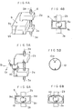
- Figures 4A and 4B are a perspective view and a sectional view, respectively, showing a different embodiment of the invention.
- This embodiment is different from the preceding embodiment of Figure 1 in that spherical movable permanent magnet 10 is used in lieu of rod-like movable premanent magnet 5 and that the magnet is movable not only in forward and backward directions but is movable in any direction in horizontal plane intersecting with paired magnetic yokes.
- this acceleration sensor comprises spherical movable permanent magnet 10, case 9 of a non-magnetic material consisting of accommodating section 9b accommodating magnet 10 and lid 9a, opposing paired magnetic yokes 2a and 2b provided on the respective upper and lower surface of case 9 and lead switch 6 provided between other ends of the paired magnetic yokes.
- Case 9 of non-magnetic material has a space, in which spherical movable permanent magnet 10 is movable. Magnet 10 is movable in case 9 not only in directions B1 or B2 and C1 or C2 but is movable in any direction in horizontal plane.
- Figure 5A shows a contact relation between spherical movable permanent magnet 10 and paired magnetic yokes 2a and 2b.
- Figure 5B shows a modification of magnet 10.
- the magnet is not a perfect sphere but has local cut and flat surfaces 10a. This has an effect of increasing the magnetic forces of attraction.
- Figure 6A shows a modification of accommodating section 9b accommodating movable permanent magnet 10.
- This modification has dish-like concave inner bottom surface 9d unlike the flat bottom surface in the case of Figures 4A, 4B.
- Figure 6B shows another modification.
- case 9 has concave ceiling and bottom surfaces.
- the case has an inclined surface such that a central portion thereof in directions of movement of the movable permanent magnet is lowest in level. This arrangement has an effect of further promoting the returning of movable permanent magnet 10 to the initial position.
- a closed magnetic circuit is provided by spherical movable permanent magnet 10, paired magnetic yokes 2a and 2b and lead switch 6.
- the areas of contact with the paired magnetic yokes and pole areas are small compared to the case of a rod-like magnet.
- the spherical movable permanent magnet therefore, may be displaced and brought to a position to be in contact with a side wall of the case with slight shocks or vibrations.
- Figures 7A and 7B show an example of design of the acceleration sensor shown in Figure 1 for actual use.
- a similar example of use of the acceleration sensor shown in Figures 4A and 4B may be obtained by replacing the rod-like movable permanent magnet with a spherical one.
- Figure 7A is a front sectional view
- Figure 7B is a plan sectional view. This example of actual use is shown upside down with respect to Figure 1.
- Case 1 of a non-magnetic material is rectangular and has upper and lower flanges.
- Rod-like movable permanent magnet 5 is accommodated in the rectangular case, and the opening of which is closed by lid 7.
- Lead switch 6 is molded with its opposite end leads 3a and 3b connected to strip-like terminals Ta and Tb in resin M entirely, i.e., except for ends of strip-like terminals Ta and Tb, thus protecting the glass tube.
- paired L-shaped magnetic yokes 2a and 2b are mounted on the case such that they have their one ends facing the opposite ends of lead switch 6 and other ends facing the position, in which movable permanent magnet 5 is disposed.
- the entire structure as described above is tightened together by U-shaped metal member P extending from one side of lower flange 1B of case 1 over the top of resin molding M to the other side of lower flange 1B.
- Metal member P is secured using holes Pa formed adjacent to its opposite ends and screws by screws inserted through holes formed in it adjacent to its opposite ends and threaded holes formed in lower flange 1B of non-magnetic case 1.
- the magnetic forces of the magnetic circuit constituted by the movable permanent magnet, magnetic yoke and lead switch may be appropriately selected for adjusting the sensitivity of detection of shocks or vibrations. Further, it is possible to adjust the detection sensitivity or response character by appropriately selecting the material, size and shape of the movable permanent magnet or adjusting the width of the magnetic gap between the magnetic yoke and movable permanent magnet of adjusting the width of a magnetic gap provided in the magnetic yoke itself.
- a lead switch with leads sealed in glass is used as switch element, and therefore it is possible to obtain a device, which is not influenced by environments, is free from erroneous operation and is highly reliable.
- Figure 9 is a perspective view, partly broken away, showing a further embodiment of the invention, and Figure 10 is a side view of the same embodiment.
- This acceleration sensor comprises box-like case 1, movable permanent magnet 5 accommodated together with surrounding magnetic fluid 24 in the case, paired magnetic yokes 2a and 2b provided opposingly on the opposite sides of case 1 and lead switch 6 provided in a lower portion of the magnetic yoke pair.
- Case 1 has a space, in which rod-like movable permanent magnet 5 surrounded by magnetic fluid 24 is movable in directions A1 and A2 .
- a closed magnetic circuit may be formed by rod-like movable permanent magnet 5 with magnetic fluid 24 there around, paired magnetic yokes 2a and 2b and lead switch 6.
- Case 1 is provided with lid 7, which covers rod-like movable permanent magnet 5 surrounded by magnetic fluid 24.
- a closed magnetic circuit is constituted by movable permanent magnet 5, magnetic fluid 24 surrounding the magnet, magnetic yokes 2a and 2b and lead switch 6.
- the magnet When an impact acceleration is applied, the magnet is moved by receiving a momentum, thus opening the magnetic circuit.
- the movable permanent magnet is returned to the initial position, to provide the closed magnetic circuit again.
- the closed magnetic circuit may be formed reliably even if there is a gap between the movable permanent magnet and magnetic yokes.
- magnetic fluid 24 provides a lubricating function, and therefore with application of an impact acceleration the movable permanent magnet can be moved smoothly, and a possibility of erroneous operation due to catching of the movable permanent magnet if eliminated.
- Figures 12 to 14 show further embodiments of the invention.
- magnetic fluid 24 is provided around spherical movable permanent magnet 10.
- the instance of Figure 13 is a modification of the embodiment of Figure 12.
- case 9 has dish-like inner surface 9d provided at the bottom.
- the instance of Figure 14 is another modification of the embodiment of Figure 12. In this case, both the ceiling and bottom of case 9 are provided with respective dish-like inner surfaces 9d.
- spherical movable permanent magnet 10 can be moved smoothly for it is surrounded by magnetic fluid 24.
- dish-like inner surface 9d provided in case 9 as shown in Figures 13 and 14, spherical movable permanent magnet 10 can readily return to the initial position.
- Figure 15 is a perspective view, partly broken away, showing a further embodiment of the invention.
- This embodiment is different from the embodiment shown in Figure 1 in that three magnetic yoke pairs 12(12a and 12b), 13(13a and 13b) and 14(14a and 14b) are provided in juxtaposing in directions A1 and A2 of movement of movable permanent magnet 5 and lead switches 15, 16 and 17 are each provided in a lower portion of each of the magnetic yoke pairs.
- a closed magnetic circuit is formed by movable permanent magnet 5, paired magnetic yokes 13a and 13b and lead switch 16, while the two other mangetic yoke pairs 12 and 14 form open magnetic circuits.
- movable permanent magnet 5 When an impact acceleration in excess of a predetermined value is applied, movable permanent magnet 5 is moved in direction A1 or A2 to form a closed magnetic circuit with either one of the two other magnetic yoke pairs 12 and 14.
- lead switches 15 and 17 By examining the on-off state of lead switches 15 and 17 it is possible to detect application of an impact acceleration in excess of a predetermined value and direction A2 or A1 of application of the impact acceleration.
- Figure 16 shows a further embodiment. This embodiment is the same as the embodiment of Figure 15 insofar as opposite end magnetic yoke pairs 12(12a and 12b) and 14(14a and 14b) and associated lead switches 15 and 17 are concerned. The difference resides in central C-shaped magnetic yoke 18, for which no lead switch is provided.
- Figure 17 shows a further embodiment. This embodiment is the same as the previous embodiment of Figure 15 insofar as the central combination of magnetic yoke pair 21(21a and 21b) and lead switch 16 is concerned but is different in that opposite side C-shaped magnetic yokes 19 and 20 are provided, for which no lead switch is provided.
- Figures 18 to 20 show modifications of the respective embodiments shown in Figures 15 to 17.
- rod-like movable permanent magnet 5 is surrounded by magnetic fluid 24. Therefore, in addition to obtaining the same operation and effects as those in the instances of Figures 15 to 17, smoother movement of movable permanent magnet and more reliable on-off operation of the magnetic circuit can be obtained.
- FIG 21 shows a further modification.
- a central portion of C-shaped magnetic yoke shown in Figure 20 is provided with central magnetic gap, in which spacer 19a is provided.
- the magnetic flux can be adjusted by suitably selecting the width of spacer 19a, thus permitting adjustment of the impact acceleration detection sensitivity.
- This arrangement is applicable as well to C-shaped magnetic yokes 18 to 20 in the cases of Figures 16, 17 and 19.
- the gap between movable permanent magnet and magnetic yokes can be a magnetic gap, and the magnetic flux can be adjusted by adjusting the distance of this gap.
- Figure 22 shows a further modification.
- magnetic yokes 2a and 2b shown in the embodiment of Figure 9 magnetic yokes 22 and 23 having tapering ends 22A and 23A are provided opposingly on opposite sides of case 1.
- a gradient of magnetic force of attraction is formed such that the magnetic force is maximum at the center of the tapering ends and becomes weaker as one goes away from the center.
- movable permanent magnet 5 may be readily returned to the initial position.
- Figure 23 shows a further modification.
- case 21 has inclined space 21A such that its central portion in the directions of movement of movable permanent magnet 5 is lowest in level, the magnet 5 being provided together with magnetic fluid 24 in the central portion of the space.
- Movable permanent magnet 5 having been displaced due to an impact acceleration thus can be readily returned to the initial position at the time of the resetting.
- each embodiment of the acceleration sensor may be utilized as acceleration sensor with a resetting function by providing an external permanent magnet or an external magnetic field of coil.
- an inert gas such as nitrogen or argon gas may be sealed in the case to prevent solidification of the magnetic fluid.
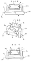
- Figure 24 is a sectional view showing sensor 31 according to the invention, and Figure 25 is a perspective view showing the same sensor 31.
- This sensor 31 comprises cylindrical permanent magnet 32 capable of forming either first or second magnetic circuit L1 or L2, lead switch 33 disposed through permanent magnet 32 for opening and closing second magnetic circuit L2 , magnetic yokes 34a and 34b opposingly disposed on opposite pole sides of permanent magnet 32 for forming first and second magnetic circuits L1 and L2 and rod-like movable magnetic member 36 disposed for movement in space 35a of non-magnetic case 35 for opening and closing first magnetic circuit L1.
- movable magnetic member 36 When an acceleration in excess of a predetermined value is applied, movable magnetic member 36 is moved in backward direction A1 or forward direction A2 crossing first magnetic circuit L1, as shown in Figure 25.
- Paired magnetic yokes 34a and 34b have respective bent ends 34c and 34d extending perpendicular to first magnetic circuit L1 such that a predetermined magnetic force of attraction is generated between end faces 34c and 34d.
- Lead switch 33 penetrates holes each formed in one end of each of pair magnetic yokes 34a and 34b. It includes a glass tube and leads 33a and 33b sealed in the glass tube and having ends outwardly projecting in opposite directions.
- Reference numeral 38 designates lead contacts.
- Second magnetic circuit L2 is constituted by permanent magnet 32, paired magnetic yokes 34a and 34b and lead switch 33.
- first magnetic circuit L1 In a stationary state without any impact acceleration applied to case 35, movable magnetic member 36 is held in first magnetic circuit L1 as shown in Figures 24 and 25 by magnetic forces of attraction between bent ends 34c and 34d of magnetic yokes 34a and 34b. In this state, first magnetic circuit L1 is closed.
- first magnetic circuit L1 With the movement of movable magnetic member 36 first magnetic circuit L1 is opened.
- second magnetic circuit L2 is closed, as shown in Figure 26, and contacts 38 of lead switch 33 are made.
- movable magnetic member 36 When the impact acceleration vanishes, movable magnetic member 36 is attracted toward first magnetic circuit L1 and is returned to the initial position.
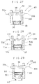
- FIGS 27 to 29 are sectional views showing modifications of sensor 31 shown in Figures 24 and 25.
- parts like those in sensor 31 are designated by like reference numerals or symbols.
- Sensor 40 shown in Figure 27 uses rod-like permanent magnet 42 in lieu of permanent magnet 32 in sensor 31. With this sensor 40, the same operation and effects as those of sensor 31 can be obtained.
- permanent magnet 52 is provided on the side of movable magnetic member 36.
- This sensor 50 specifically, comprises permanent magnet 52 provided adjacent to ends of magnetic yokes 54a and 54b and capable of forming first or second magnetic circuit L21 or L22, lead switch 33 penetrating other ends of magnetic yokes 54a and 54b for opening and closing second magnetic circuit L22, non-magnetic case 55 provided in the vicinity of permanent magnet 52 and having the same construction as that in sensor 31, and cylindrical movable magnetic member 56 movable such as to open and close first magnetic circuit L21.
- first magnetic circuit L21 In a stationary state without any impact acceleration applied to movable magnetic member 56, movable magnetic member 56 is held attracted to permanent magnet 52, and first magnetic circuit L21 is closed. When first magnetic circuit L21 is closed, second magnetic circuit L22 is open, and contacts 38 of lead switch 33 are broken apart.
- movable magnetic member 56 When an impact acceleration in excess of a predetermined value is applied to movable magnetic member 56 in forward direction A2 , movable magnetic member 56 is moved by the acceleration in forward direction A2 , i.e., away from permanent magnet 52.
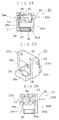
- Figure 30 is a sectional view showing further sensor 70 embodying the invention, and Figure 31 is a perspective view showing the same sensor 70.
- This sensor 70 is 90 degrees out of orientation of sensor 31 shown in Figures 24 and 25 for detecting impact accelerations in horizontal directions in a range of 360 degrees.
- This sensor is the same as sensor 31 except for spherical movable magnetic member 76 is used in lieu of cylindrical movable magnetic member 36, and parts having like functions are designated by like reference numerals or symbols.
- Spherical movable magnetic member 76 is disposed for movement in horizontal directions in a range of 360 degrees in space 75c of non-magnetic case 75, and it opens and closes first magnetic circuit L1 like member 36 in sensor 31.
- movable magnetic member 76 When an acceleration in excess of a predetermined value is applied, movable magnetic member 76 is movable not only in horizontal directions B1 , B2 , C1 and C2 but in any direction crossing first magnetic circuit L1, as shown in Figure 32.
- Pair magnetic yokes 74a and 74b have bent ends 74c and 74d extending perpendicular to first magnetic circuit L1 for generation of a predetermined magnetic force of attraction as in sensor 31.
- Second magnetic circuit L2 is constituted by permanent magnet 32, pair magnetic yokes 74a and 74b and lead switch 33.
- Non-magnetic case 75 may be readily manufactured such that it consists of lids 75a and 75b for covering movable magnetic member 76.
- first magnetic circuit L1 In a stationary state without any impact acceleration applied to case 75, as in sensor 31, movable magnetic member 76 is held in first magnetic circuit L1 as shown in Figure 33. In this state, first magnetic circuit L1 is closed, while second magnetic circuit L2 is open. Also, contacts 38 of lead switch 33 are broken apart.
- first magnetic circuit L1 With the movement of movable magnetic member 76, first magnetic circuit L1 is opened.
- second magnetic circuit L2 is closed, as shown in Figure 34. At this time, contacts 38 of lead switch 33 are made.
- movable magnetic member 76 When the impact acceleration vanishes, movable magnetic member 76 is attracted toward first magnetic circuit L1 and is returned to the initial position.
- sensor 70 in addition to the effects obtainable with sensor 31, it is readily possible to detect impact accelerations in all circumferential directions.
- the sensor When the sensor is applied to a vehicle or the like, it is operated not only in case of collision from the front but also in cases of collisions in oblige and sidewise directions.
- one sensor can be sufficiently used for the cases of collisions in all directions in a range of 360 degrees.
- Movable magnetic member 76 may be of a shape as shown in Figure 35. It is spherical with local cut flat surfaces 86a which are in contact with the inner wall surfaces of case 75, i.e., perpendicular to first magnetic circuit L1 . This arrangement has an effect of enhancing the magnetic force of attraction.
- Case 75 may be formed with a concave bottom inner surface for receiving movable magnetic member 76 as shown in Figure 36 or may be formed with concave top and bottom inner surfaces to facilitate the returning operation of movable magnetic member 76 as shown in Figure 37.
- Figure 38 shows a construction comprising three permanent magnets 82A to 82C, three magnetic yokes 84A to 84C and three lead switches 83A to 83C, these components being arranged in respective combinations juxtaposed with one another. This arrangement permits detection of both the magnitude and direction of accelerations.
Landscapes
- Physics & Mathematics (AREA)
- General Physics & Mathematics (AREA)
- Switches Operated By Changes In Physical Conditions (AREA)
Priority Applications (1)
| Application Number | Priority Date | Filing Date | Title |
|---|---|---|---|
| EP91101789A EP0498018A1 (fr) | 1991-02-08 | 1991-02-08 | Capteur d'accélération |
Applications Claiming Priority (1)
| Application Number | Priority Date | Filing Date | Title |
|---|---|---|---|
| EP91101789A EP0498018A1 (fr) | 1991-02-08 | 1991-02-08 | Capteur d'accélération |
Publications (1)
| Publication Number | Publication Date |
|---|---|
| EP0498018A1 true EP0498018A1 (fr) | 1992-08-12 |
Family
ID=8206386
Family Applications (1)
| Application Number | Title | Priority Date | Filing Date |
|---|---|---|---|
| EP91101789A Withdrawn EP0498018A1 (fr) | 1991-02-08 | 1991-02-08 | Capteur d'accélération |
Country Status (1)
| Country | Link |
|---|---|
| EP (1) | EP0498018A1 (fr) |
Cited By (1)
| Publication number | Priority date | Publication date | Assignee | Title |
|---|---|---|---|---|
| JP2002181505A (ja) * | 2000-12-14 | 2002-06-26 | Asahi Kasei Electronics Co Ltd | 磁気センサユニット |
Citations (5)
| Publication number | Priority date | Publication date | Assignee | Title |
|---|---|---|---|---|
| US3459911A (en) * | 1968-01-16 | 1969-08-05 | Inertia Switch Inc | Inertia switch with magnetic shunting |
| FR2223699A1 (fr) * | 1973-03-26 | 1974-10-25 | Illinois Tool Works | |
| US3942051A (en) * | 1974-02-13 | 1976-03-02 | Canadian Patents And Development Limited | Shock actuated electrical pulse generator |
| EP0293784A2 (fr) * | 1987-05-30 | 1988-12-07 | Nippon Soken, Inc. | Capteur d'accélération |
| EP0341464A2 (fr) * | 1988-05-11 | 1989-11-15 | W. Günther GmbH | Senseur d'accélération ou de décélération |
-
1991
- 1991-02-08 EP EP91101789A patent/EP0498018A1/fr not_active Withdrawn
Patent Citations (5)
| Publication number | Priority date | Publication date | Assignee | Title |
|---|---|---|---|---|
| US3459911A (en) * | 1968-01-16 | 1969-08-05 | Inertia Switch Inc | Inertia switch with magnetic shunting |
| FR2223699A1 (fr) * | 1973-03-26 | 1974-10-25 | Illinois Tool Works | |
| US3942051A (en) * | 1974-02-13 | 1976-03-02 | Canadian Patents And Development Limited | Shock actuated electrical pulse generator |
| EP0293784A2 (fr) * | 1987-05-30 | 1988-12-07 | Nippon Soken, Inc. | Capteur d'accélération |
| EP0341464A2 (fr) * | 1988-05-11 | 1989-11-15 | W. Günther GmbH | Senseur d'accélération ou de décélération |
Cited By (1)
| Publication number | Priority date | Publication date | Assignee | Title |
|---|---|---|---|---|
| JP2002181505A (ja) * | 2000-12-14 | 2002-06-26 | Asahi Kasei Electronics Co Ltd | 磁気センサユニット |
Similar Documents
| Publication | Publication Date | Title |
|---|---|---|
| US5248861A (en) | Acceleration sensor | |
| US4596971A (en) | Magnetic circuit device | |
| US6826844B2 (en) | Downsized sensor unit with increased accuracy | |
| US8400241B2 (en) | Magnetically-triggered proximity switch | |
| US4057773A (en) | Magnetic switch | |
| US5929731A (en) | Balanced magnetic proximity switch assembly | |
| US4041427A (en) | Reed switching opening and closing device | |
| US6499220B2 (en) | Inclination sensor | |
| US4339734A (en) | Encased miniature relay | |
| US4988839A (en) | Momentum activated electrical switch | |
| WO2002004770A1 (fr) | Dispositif de détection | |
| WO1995022741A1 (fr) | Appareil capteur et lampe equipee d'un tel appareil capteur | |
| US6392331B1 (en) | Bistable actuator | |
| US6329618B1 (en) | Reed switch with shock sensing mass within the glass capsule | |
| US3659062A (en) | Acceleration responsive switches employing a plurality of masses | |
| US5675134A (en) | Traffic accident detecting sensor for a passenger protection system in a vehicle | |
| JPH0372267A (ja) | 加速度センサ | |
| JPH03108671A (ja) | 加速度センサ | |
| US3166652A (en) | Magnetic reed switch with latching feature | |
| US4001744A (en) | Electrical switch | |
| US3176096A (en) | Magnetic proximity-sensing devices | |
| JPH06213369A (ja) | 多連方向切換弁の切換位置検出装置 | |
| JP2006208342A (ja) | 傾斜振動センサー | |
| SU957308A1 (ru) | Путевой переключатель "МИР | |
| SU964771A1 (ru) | Концевой выключатель |
Legal Events
| Date | Code | Title | Description |
|---|---|---|---|
| PUAI | Public reference made under article 153(3) epc to a published international application that has entered the european phase |
Free format text: ORIGINAL CODE: 0009012 |
|
| AK | Designated contracting states |
Kind code of ref document: A1 Designated state(s): DE FR GB |
|
| 17P | Request for examination filed |
Effective date: 19930208 |
|
| 17Q | First examination report despatched |
Effective date: 19940318 |
|
| STAA | Information on the status of an ep patent application or granted ep patent |
Free format text: STATUS: THE APPLICATION IS DEEMED TO BE WITHDRAWN |
|
| 18D | Application deemed to be withdrawn |
Effective date: 19940929 |