EP0498455A2 - Méthode d'enregistrement magnétooptique et appareil magnétooptique pour l'enregistrement /reproduction - Google Patents
Méthode d'enregistrement magnétooptique et appareil magnétooptique pour l'enregistrement /reproduction Download PDFInfo
- Publication number
- EP0498455A2 EP0498455A2 EP92102084A EP92102084A EP0498455A2 EP 0498455 A2 EP0498455 A2 EP 0498455A2 EP 92102084 A EP92102084 A EP 92102084A EP 92102084 A EP92102084 A EP 92102084A EP 0498455 A2 EP0498455 A2 EP 0498455A2
- Authority
- EP
- European Patent Office
- Prior art keywords
- magneto
- recording
- reproducing
- light beam
- optic
- Prior art date
- Legal status (The legal status is an assumption and is not a legal conclusion. Google has not performed a legal analysis and makes no representation as to the accuracy of the status listed.)
- Granted
Links
Images



Classifications
-
- G—PHYSICS
- G11—INFORMATION STORAGE
- G11B—INFORMATION STORAGE BASED ON RELATIVE MOVEMENT BETWEEN RECORD CARRIER AND TRANSDUCER
- G11B7/00—Recording or reproducing by optical means, e.g. recording using a thermal beam of optical radiation by modifying optical properties or the physical structure, reproducing using an optical beam at lower power by sensing optical properties; Record carriers therefor
- G11B7/007—Arrangement of the information on the record carrier, e.g. form of tracks, actual track shape, e.g. wobbled, or cross-section, e.g. v-shaped; Sequential information structures, e.g. sectoring or header formats within a track
-
- G—PHYSICS
- G11—INFORMATION STORAGE
- G11B—INFORMATION STORAGE BASED ON RELATIVE MOVEMENT BETWEEN RECORD CARRIER AND TRANSDUCER
- G11B11/00—Recording on or reproducing from the same record carrier wherein for these two operations the methods are covered by different main groups of groups G11B3/00 - G11B7/00 or by different subgroups of group G11B9/00; Record carriers therefor
- G11B11/10—Recording on or reproducing from the same record carrier wherein for these two operations the methods are covered by different main groups of groups G11B3/00 - G11B7/00 or by different subgroups of group G11B9/00; Record carriers therefor using recording by magnetic means or other means for magnetisation or demagnetisation of a record carrier, e.g. light induced spin magnetisation; Demagnetisation by thermal or stress means in the presence or not of an orienting magnetic field
- G11B11/105—Recording on or reproducing from the same record carrier wherein for these two operations the methods are covered by different main groups of groups G11B3/00 - G11B7/00 or by different subgroups of group G11B9/00; Record carriers therefor using recording by magnetic means or other means for magnetisation or demagnetisation of a record carrier, e.g. light induced spin magnetisation; Demagnetisation by thermal or stress means in the presence or not of an orienting magnetic field using a beam of light or a magnetic field for recording by change of magnetisation and a beam of light for reproducing, i.e. magneto-optical, e.g. light-induced thermomagnetic recording, spin magnetisation recording, Kerr or Faraday effect reproducing
- G11B11/10502—Recording on or reproducing from the same record carrier wherein for these two operations the methods are covered by different main groups of groups G11B3/00 - G11B7/00 or by different subgroups of group G11B9/00; Record carriers therefor using recording by magnetic means or other means for magnetisation or demagnetisation of a record carrier, e.g. light induced spin magnetisation; Demagnetisation by thermal or stress means in the presence or not of an orienting magnetic field using a beam of light or a magnetic field for recording by change of magnetisation and a beam of light for reproducing, i.e. magneto-optical, e.g. light-induced thermomagnetic recording, spin magnetisation recording, Kerr or Faraday effect reproducing characterised by the transducing operation to be executed
-
- G—PHYSICS
- G11—INFORMATION STORAGE
- G11B—INFORMATION STORAGE BASED ON RELATIVE MOVEMENT BETWEEN RECORD CARRIER AND TRANSDUCER
- G11B11/00—Recording on or reproducing from the same record carrier wherein for these two operations the methods are covered by different main groups of groups G11B3/00 - G11B7/00 or by different subgroups of group G11B9/00; Record carriers therefor
- G11B11/10—Recording on or reproducing from the same record carrier wherein for these two operations the methods are covered by different main groups of groups G11B3/00 - G11B7/00 or by different subgroups of group G11B9/00; Record carriers therefor using recording by magnetic means or other means for magnetisation or demagnetisation of a record carrier, e.g. light induced spin magnetisation; Demagnetisation by thermal or stress means in the presence or not of an orienting magnetic field
- G11B11/105—Recording on or reproducing from the same record carrier wherein for these two operations the methods are covered by different main groups of groups G11B3/00 - G11B7/00 or by different subgroups of group G11B9/00; Record carriers therefor using recording by magnetic means or other means for magnetisation or demagnetisation of a record carrier, e.g. light induced spin magnetisation; Demagnetisation by thermal or stress means in the presence or not of an orienting magnetic field using a beam of light or a magnetic field for recording by change of magnetisation and a beam of light for reproducing, i.e. magneto-optical, e.g. light-induced thermomagnetic recording, spin magnetisation recording, Kerr or Faraday effect reproducing
- G11B11/10532—Heads
-
- G—PHYSICS
- G11—INFORMATION STORAGE
- G11B—INFORMATION STORAGE BASED ON RELATIVE MOVEMENT BETWEEN RECORD CARRIER AND TRANSDUCER
- G11B11/00—Recording on or reproducing from the same record carrier wherein for these two operations the methods are covered by different main groups of groups G11B3/00 - G11B7/00 or by different subgroups of group G11B9/00; Record carriers therefor
- G11B11/10—Recording on or reproducing from the same record carrier wherein for these two operations the methods are covered by different main groups of groups G11B3/00 - G11B7/00 or by different subgroups of group G11B9/00; Record carriers therefor using recording by magnetic means or other means for magnetisation or demagnetisation of a record carrier, e.g. light induced spin magnetisation; Demagnetisation by thermal or stress means in the presence or not of an orienting magnetic field
- G11B11/105—Recording on or reproducing from the same record carrier wherein for these two operations the methods are covered by different main groups of groups G11B3/00 - G11B7/00 or by different subgroups of group G11B9/00; Record carriers therefor using recording by magnetic means or other means for magnetisation or demagnetisation of a record carrier, e.g. light induced spin magnetisation; Demagnetisation by thermal or stress means in the presence or not of an orienting magnetic field using a beam of light or a magnetic field for recording by change of magnetisation and a beam of light for reproducing, i.e. magneto-optical, e.g. light-induced thermomagnetic recording, spin magnetisation recording, Kerr or Faraday effect reproducing
- G11B11/10582—Record carriers characterised by the selection of the material or by the structure or form
- G11B11/10586—Record carriers characterised by the selection of the material or by the structure or form characterised by the selection of the material
Definitions
- the present invention relates to a magneto-optic recording method and a magneto-optic recording/reproducing apparatus.
- the recording bit In carrying out a magneto-optic recording/reproducing method that forms an information recording bit, i.e. a bubble magnetic domain, by magnetic field modulation or light modulation by local heating, for example with a laser beam, and reads the recorded information by the Kerr effect or the Faraday effect, the recording bit needs to be miniaturized to increase magneto-optic recording density.
- the miniaturization of the recording bit entails problems in resolution. Resolution is dependent, for example, on the radius R of the spot of the light beam, for example a laser beam, employed for recording and reproducing as a function of the wavelength ⁇ of the laser beam and the numerical aperture N.A. of the objective lens (R ⁇ ⁇ /N.A.).
- Figure 1A is a typical top plan view of a recording pattern.
- a method of reproducing binary signals "1" and "0" recorded in recording bits 4, i.e. shaded portions in Figure 1A, of a magneto-optic recording medium 3, such as a magneto-optic disk, will be described.
- a reading laser beam forms a circular spot 5 on the magneto-optic recording medium 3.
- the spot 5 includes a recording bit 4 as shown in Figure 1B or the spot 5 does not include any recording bit 4 as shown in Figure 1C.
- the output signal has, for example, a sinusoidal waveform whose amplitude varies alternately above and below a reference level 0 as shown in Figure 1D.
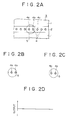
- the spot 5 includes a plurality of recording bits 4. Since a reproduced output signal provided when the two recording bits 4a and 4b among the successive three recording bits 4a, 4b and 4c are included in one spot 5 as shown in Figure 2B and a reproduced output signal provided when the two recording bits 4b and 4c are included in one spot 5 as shown in Figure 2C are the same and cannot be discriminated from each other, the reproduced output signals form, for example, a straight line as shown in Figure 2D.
- the magneto-optic recording/reproducing system Since the conventional magneto-optic recording/reproducing system reads directly the recording bits 4 recorded on the magneto-optic recording medium 3, restrictions on the reproducing resolution cause problems in S/N (C/N - carrier-to-noise ratio), and hence the magneto-optic recording/reproducing system is unable to achieve high-density recording and reproducing, even if the magneto-optic recording/reproducing system is capable of high-density recording, i.e., high-density bit formation.
- the MSR system enhances the reproducing resolution by reading only the recording bit 4 of a temperature in a predetermined temperature range on a magneto-optic recording medium by utilizing a temperature distribution formed by the relative movement between the magento-optic recording medium and the spot 5 of the reproducing beam.
- the MSR systems are classified into those of a so-called emergence type and those of an extinction type.
- Figure 3A is a typical top plan view of a recording pattern formed on a magneto-optic recording medium 10
- Figure 3B is a typical sectional view showing a state of magnetization of the magneto-optic recording medium 10.
- the magneto-optic recording medium 10 moves in the direction of an arrow D relative to a spot 5.
- the magneto-optic recording medium 10 is, for example, a magneto-optic disk having at least a reproducing layer 11 and a recording layer 13 formed of perpendicularly magnetizable films, respectively.
- the reproducing layer 11, the recording layer 13 and an intermediate layer 12 formed between the reproducing layer 11 and the recording layer 13 are provided.
- Arrows in the layers 11, 12 and 13 in Figure 3B indicate the direction of magnetic moment.
- magnetic domains indicated by downward arrows are in an initial state.
- Information recording bits 4 are formed at least in the recording layer 13 with magnetic domains magnetized upwardly.
- an external initializing magnetic field H i is applied to the magneto-optic recording medium 10 to magnetize the reproducing layer 11 downward, as viewed in Figure 3B, for initialization.
- the recording bits 4 of the reproducing layer 11 are extinguished by initialization, the respective directions of magnetization of regions in the reproducing layer 11 and the recording layer 13 corresponding to the recording bits 4 are maintained reverse to each other by magnetic domain walls formed in the intermediate layer 12, so that the recording bits 4 remain in latent recording bits 41.
- a reproducing magnetic field H r of a direction reverse to that of the initializing magnetic field H i is applied at least to the reproducing regions of the magnetic recording medium 10.
- the region having the initialized latent recording bit 41 comes under the spot 5. Since the duration of irradiation with the beam at the front side, the left side in Figures 3A and 3B, on the magneto-optic recording medium 10 with respect to the direction of movement is longer, a high-temperature region 14 is formed in the front side of the spot 5 as indicated by a shaded area enclosed by a broken line a .
- the recording bit 4 can be read by detecting the rotation of the plane of polarization of the spot 5 by magneto-optic effect, namely, the Kerr effect or Faraday effect, corresponding to the direction of magnetization of the reproducing layer 11.
- magneto-optic effect namely, the Kerr effect or Faraday effect
- Latent recording bits 41 in a low-temperature region 15, other than the high-temperature region 14, in the spot 5 do not emerge into the reproducing layer 11, and hence the reproducible recording bit 4 is included only in the narrow high-temperature region 14. Therefore, even if information is recorded in a high recording density on the magneto-optic recording medium 10 capable of high-resolution recording, in which a plurality of recording bits 4 are included in the spot 5, only one of the recording bits 4 can be read for high-resolution signal reproducing.
- the initializing magnetic field H i , the reproducing magnetic field H r , the respective coercive forces, values of thickness, intensities of magnetization, and values of domain wall energy of the magnetic layers are determined selectively according to the temperature of the high-temperature region 14 and that of the low-temperature region 15.
- the coercive force H c1 , thickness h1 and saturation magnetization M s1 of the reproducing layer 11, and the coercive force H c3 , thickness h3 and saturation magnetization M s3 of the recording layer 13 must meet the expression of Mathematical 1.
- H1 > H c1 + ⁇ w2 /2Ms s1 ⁇ h1
- ⁇ w2 is the interfacial domain wall energy between the reproducing layer 11 and the recording layer 13.
- Mathematical 2 An expression of Mathematical 2 must be met to maintain the informatien recorded in the recording layer 13 by the magnetic field.
- Mathematical 3 must be met to maintain the magnetic domain walls formed in the intermediate layer 12 between the reproducing layer 11 and the recording layer 13 after the initializing magnetic field H i has been applied to the magneto-optic recording medium.
- Mathematical 4 must be met to heat the high-temperature region 14 at a selected temperature T H .
- the magnetization of the latent recording bits 41 of the recording layer 13 can be transferred only in regions of the reproducing layer 11 corresponding to the magnetic domain walls of the intermediate layer 12 to form recording bits 4 by applying the reproducing magnetic field H r meeting the expression of Mathematical 4.
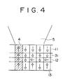
- the MSR system may employ a four-layer magneto-optic recording medium additionally provided with an auxiliary reproducing layer 31 between the reproducing layer 11 and the intermediate layer 12 as shown in a typical sectional view in Figure 4.
- the auxiliary reproducing layer 31 supplements the characteristics of the reproducing layer 11 to compensate the coercive force of the reproducing layer 11 at room temperature to stabilize the magnetization of the reproducing layer 11 caused by the initializing magnetic field H i , regardless of the existence of magnetic domain walls, and to decrease the coercive force sharply at a temperature near the reproducing temperature so that the magnetic domain walls of the intermediate layer 12 expand into the auxiliary reproducing layer 31 to finally invert the reproducing layer 11 and to extinguish the magnetic domain walls for satisfactory emergence of the recording bits.
- the coercive force H c1 of the reproducing layer 11 of a four-layer magneto-optic recording medium provided with the auxiliary reproducing layer 31 is substituted by H CA expressed by the expression in Mathematical 5, and where ⁇ w2 /M s1 ⁇ h1 is substituted by ⁇ w2 /(M s1 ⁇ h1 + M s1s ⁇ h 1s ).
- H CA (M s1 ⁇ h1 ⁇ H c1 + M s1s ⁇ h 1s ⁇ H c1s )/(M s1 ⁇ h1 + M s1s ⁇ h 1s )
- H c1 ⁇ H CA H c1s for the MSR system of an emergence type
- M s1s , H c1s and h 1s are the magnetization, coercive force and thickness, respectively, of the auxiliary reproducing layer 31.
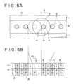
- Figure 5A is a typical top plan view of a recording pattern formed on a magneto-optic recording medium 10
- Figure 5B is a typical sectional view showing a state of magnetization, in which parts like or corresponding to those shown in Figures 3A and 3B are denoted by the same reference characters. The description thereof will be omitted to avoid duplication.
- This magneto-optic recording medium does not need any initializing magnetic field H i .
- the reproducing operation for reproducing information recorded on the magneto-optic recording medium 10 will be described.
- the high-temperature region 14 is heated so that an expression in Mathematical 6 is satisfied, and then an external reproducing magnetic field H r is applied to the magneto-optic recording medium 10 to extinguish recording bits 4 in the high-temperature region 14 included in the spot 5 of a laser beam in the reproducing layer 11 magnetized downward as viewed in Figure 5B.
- the MSR system of the extinction type enables information stored in only the recording bits 4 in the low-temperature region 15 in the spot 5 to be reproduced to improve the resolution.
- the conditions including the coercive force, are determined so that the recording bits 4 of the recording layer 13 remain in latent recording bits 41 in an extinction state to hold the magnetization of the recording layer 13, and the recording bits 4 are transferred to the reproducing layer 11 and held therein in a reproducible state at room temperature.
- the foregoing MSR systems of an emergence type and an extinction type reproduce the recording bit in a local region included in the spot of the reproducing laser beam to reproduce the information in an enhanced resolution.
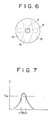
- the MSR system of a combined type forms a high-temperature region 14, a middle-temperature region 16 and a low-temperature region 15 in the front portion, middle portion and rear portion with respect to the direction of movement of the magneto-optic recording medium relative to a spot 5 as shown in Figure 6, and utilizes the high-temperature region 14 for the functions of the extinction type described with reference to Figures 5A and 5B, and the middle-temperature region 16 and the low-temperature region 15 for the functions of the emergence type described with reference to Figures 3A and 3B.
- the MSR system of a combined system is able to make only a recording bit 4 emerge into the reproducing layer 11, a shaded circle in Figure 6, and included in the narrow middle-temperature region 16 between the high-temperature region 14 and the low-temperature region 15. Accordingly, the MSR system of a combined type is capable of reproducing recorded information in a higher resolution.
- the MSR systems are able to reproduce recorded information in a very high resolution regardless of the wavelength ⁇ of the laser beam and the numerical aperture N.A. of the objective lens.
- the MSR system need not use a reading light beam of a particularly short wavelength and is able to determine the wavelength of a reading light beam taking into consideration magneto-optic effect, heating effect, and the sensitivity of the optical detector.
- the MSR system is able to reproduce recorded information in a high resolution even if the same uses a semiconductor laser beam having a comparatively large wavelength, such as 780 nm.
- the MSR system capable of reproducing recorded information in a very high reproducing resolution enables high-density recording, namely, miniaturization of recording bits and reduction of the pitch of recording bits.
- the magneto-optic recording medium must be heated by the laser beam in a temperature distribution having a peak corresponding to a temperature T w capable of forming a recording bit, for example, the Curie temperature, and the recording bit must be formed in a width corresponding to a small region ⁇ p as shown in Figures 5A and 5B, which requires strict conditions for materials forming the magnetic layers of the magneto-optic recording medium and the power of the recording laser beam.
- a magneto-optic recording/reproducing apparatus employs a magneto-optic recording medium having at least a reproducing layer and a recording layer which changes the state of magnetization of the reproducing layer.
- the reproducing layer is irradiated with a reading light beam to read information recorded in a region smaller than a spot of the reading light beam by the magneto-optic effect.
- the wavelength of a recording light beam is far smaller than that of the reading light beam.
- a minimum ratio between the wavelength of the recording light beam to that of the reading light beam is 1:3.
- a magneto-optic recording method in accordance with the present invention employs a magneto-optic recording medium 10 such as described with reference to Figures 3A to 6, having at least a reproducing layer 11 and a recording layer 13, from which recorded information is read by the magneto-optic effect in a region smaller than the spot 5 of a reading light beam by simultaneously changing the state of magnetization of the reproducing layer 11 and irradiating the same with the reading light beam.
- the wavelength of the recording light beam used for recording information in the magneto-optic recording medium is far smaller than that of the reading light beam.
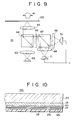
- a magneto-optic recording/reproducing apparatus in accordance with the present invention employs a magneto-optic recording medium 100 as shown in Figures 8, 9, and 10 having at least a reproducing layer 110 and a recording layer 130, from which recorded information is read by the magneto-optic effect in a small region smaller than the spot of a reading light beam by simultaneously changing the state of magnetization of the reproducing layer 110 and irradiating the same with the reading light beam.
- a recording optical head 51 is disposed relative to a magneto-optic recording medium 100 as shown in Figure 8, and a reproducing optical head 61 is disposed relative to the magneto-optic recording medium 100 as shown in Figure 9.
- the wavelength of a light beam emitted by the recording optical head 51 is far smaller than that of a light beam emitted by the reproducing optical head 61.
- the present invention uses a recording light beam having a wavelength far smaller than that of a reproducing light beam for recording, recording bits can be miniaturized and the pitch of the recording bits can be reduced.
- Figure 8 shows a recording optical head by way of example.
- This recording optical head applies an external recording magnetic field H M to a magneto-optic recording medium for recording by light modulation.
- the recording optical head employs a recording light source 53 that emits green light of 532 nm in wavelength.
- the light emitted by the recording light source 53 travels through a converging lens system 54, a light modulator 55, a collimator lens 56 and an objective lens 57, and is focused on the magneto-optic recording medium 100, such as a magneto-optic disk.
- the recording light source 53 employs a green laser that emits second harmonic green laser light of 532 nm in wavelength by applying the light emitted by a Nd:YAG laser (1064 nm in wavelength) excited by a semiconduotor laser beam of 810 nm in wavelength to a nonlinear optical crystal of, for example, KTP (KTiOPO4) .
- the light modulator may be an acousto-optic modulator, i.e., a so-called AMO.
- the AMO 55 modulates the laser beam according to recording signals represented by "1" and "0".
- a predetermined recording magnetic field H M is applied to the magneto-optic recording medium 100 and, at the same time, a region of the magneto-optic recording medium 100 in which a recording bit is to be formed is heated at a temperature T w , such as a temperature not lower than the Curie temperature, by irradiating the region with a laser beam having a short wavelength and modulated according to a recording signal, for example, a recording signal represented by "1", to magnetize the region in the same direction as the recording magnetic field H M to record the recording signal represented by "1" in a recording bit.
- a temperature T w such as a temperature not lower than the Curie temperature
- a reproducing optical head 61 has a reproducing light source 62 that emits a reproducing light beam having a comparatively large wavelength.
- the reproducing light source is a semiconductor laser that emits linearly polarized light of 780 nm in wavelength.
- a minimum ratio between the wavelength of the recording light beam to that of the reading light beam is 1:3.
- the reading light beam emitted by the reproducing light source 62 travels through, for example, a collimator lens 63, a beam splitter 64 and an objective lens, and is focused on the magneto-optic recording medium 100.
- the reflected light beam reflected by the magneto-optic recording medium 100 namely, the light beam rotated by the Kerr rotation effect of the recording bit, is split by the beam splitter 64.
- the split reflected light beam travels through a half-wave plate 66.
- the split reflected light beam is split by a beam splitter 67.
- the split light beams travel through converging lenses 68 and 69, respectively, and fall on optical detectors 70 and 71, such as pin-type diodes, respectively.
- the output signals of the optical detectors 70 and 71 are picked up differentially to read the recorded signal.
- the magneto-optic recording medium 100 has a transparent dielectric layer 23 of, for example, a SiN film of 800 ⁇ in thickness that serves as a protective film or an interference film, a reproducing layer 110, an auxiliary reproducing layer 21, an intermediate layer 120 and a recording layer 130 formed sequentially in that order by continuous sputtering on a transparent substrate 20 of, for example, glass, an acrylic resin or a polycarbonate resin.
- the reproducing layer 110, the auxiliary reproducing layer 21, the intermediate layer 120 and the recording layer 130 are magnetic films of rare earth metal-transition metal alloys.
- the reproducing layer 110 is, for example, a perpendicularly magnetizable film of Gd23(Fe85Co15)77 having a thickness of, for example, 300 ⁇ .
- the auxiliary reproducing layer 31 is, for example, a perpendicularly magnetizable film of Tb12(Fe95Co5)88 having a thickness of, for example, 100 ⁇ .
- the intermediate layer 120 is, for example, a magnetic film of Gd20(Fe95Co5)80 having a thickness of, for example, 100 ⁇ and small in perpendicular anisotropy.
- the recording layer 130 is, for example, a perpendicularly magnetizable film of Tb25(Fe85Co15)75 having a thickness of, for example, 400 ⁇ .
- the reproducing operation of the reproducing optical head is carried out by the foregoing MSR system, namely, the MSR system of an emergence type described with reference to Figures 3A and 3B, the MSR system of an extinction type described with reference to Figures 5A and 5B, or the MSR system of a combined type.
- a possible magneto-optic recording medium need not be limited to the foregoing magneto-optic recording medium of a four-layer construction having the reproducing layer 110, the auxiliary reproducing layer 21, the intermediate layer 120 and the recording layer 130; a magneto-optic recording medium of a three-layer construction having a reproducing layer 110, an intermediate layer 120 and a recording layer 130 formed of rare earth metal-transition metal alloys may be employed.
- a possible magneto-optic recording medium of a three-layer construction may have a reproducing layer 110 of Gd23(Fe85Co15)77, an intermediate layer 120 of Tb18Fe82 and a recording layer 130 of Tb25(Fe85Co15)75.
- compositions of the layers are not restrictive and varieties of compositions are possible.
- the recording optical head 51 and the reproducing optical head 61 may be incorporated into a magneto-optic recording/ reproducing driver or may be formed individually in a recording driver and a reproducing driver, respectively.
- the present invention uses for recording information a recording light beam of a wavelength far smaller than that of a reproducing light beam and hence information can surely and easily be recorded in a high recording density at least with respect to the scanning direction of the light spot, namely, in a high scanning density.
- the present invention eliminates the strict conditions for the composition and temperature characteristics of the component layers of the magneto-optic recording medium and improves the reliability.
Applications Claiming Priority (2)
| Application Number | Priority Date | Filing Date | Title |
|---|---|---|---|
| JP3018078A JPH04255947A (ja) | 1991-02-08 | 1991-02-08 | 光磁気記録方法と光磁気記録再生装置 |
| JP18078/91 | 1991-02-08 |
Publications (3)
| Publication Number | Publication Date |
|---|---|
| EP0498455A2 true EP0498455A2 (fr) | 1992-08-12 |
| EP0498455A3 EP0498455A3 (en) | 1992-12-09 |
| EP0498455B1 EP0498455B1 (fr) | 1997-04-16 |
Family
ID=11961620
Family Applications (1)
| Application Number | Title | Priority Date | Filing Date |
|---|---|---|---|
| EP92102084A Expired - Lifetime EP0498455B1 (fr) | 1991-02-08 | 1992-02-07 | Méthode d'enregistrement magnétooptique et appareil magnétooptique pour l'enregistrement /reproduction |
Country Status (7)
| Country | Link |
|---|---|
| US (1) | US5208799A (fr) |
| EP (1) | EP0498455B1 (fr) |
| JP (1) | JPH04255947A (fr) |
| KR (1) | KR100239812B1 (fr) |
| AT (1) | ATE151907T1 (fr) |
| CA (1) | CA2060535A1 (fr) |
| DE (1) | DE69218986T2 (fr) |
Cited By (5)
| Publication number | Priority date | Publication date | Assignee | Title |
|---|---|---|---|---|
| EP0588636A1 (fr) * | 1992-09-18 | 1994-03-23 | Nikon Corporation | Milieu d'enregistrement magnéto-optique, capable d'être surécrit |
| EP0603670A3 (en) * | 1992-12-21 | 1994-08-31 | Nec Corp | Magnetooptical recording medium, recording and playback method and apparatus for the same. |
| EP0594423A3 (fr) * | 1992-10-21 | 1994-11-30 | Canon Kk | Appareil d'enregistrement et de reproduction magnéto-optique d'information. |
| US5699342A (en) * | 1994-02-07 | 1997-12-16 | Mitsubishi Denki Kabushiki Kaisha | Method of and device for recording and playing back an optical disk having a test playback region utilizing pits of minimum size for controlling the power of the laser |
| WO1998009285A1 (fr) * | 1996-08-27 | 1998-03-05 | Quinta Corporation | Systeme de stockage de donnees magneto-optique a haute efficacite |
Families Citing this family (16)
| Publication number | Priority date | Publication date | Assignee | Title |
|---|---|---|---|---|
| US5357493A (en) * | 1987-07-24 | 1994-10-18 | Matsushita Electric Industrial Co., Ltd. | Magneto-optic memory device for overwriting information on magneto-optic recording medium by using a pair of light spots without using an external magnetic field |
| DE69119414T2 (de) * | 1991-02-05 | 1997-01-02 | Sony Corp | Verfahren zur Wiedergabe eines Signals aus einem optischen Aufzeichnungsmedium |
| WO1992015093A1 (fr) * | 1991-02-13 | 1992-09-03 | Sony Corporation | Procede pour la reproduction des signaux dans un support d'enregistrement optique |
| JPH0520725A (ja) * | 1991-07-11 | 1993-01-29 | Sony Corp | 光ピツクアツプ装置 |
| US5363363A (en) * | 1992-10-16 | 1994-11-08 | Eastman Kodak Company | Apparatus and method for laser noise cancellation in an optical storage system using a front facet monitor signal |
| JP3229907B2 (ja) * | 1992-11-09 | 2001-11-19 | パイオニア株式会社 | 光記録媒体及び光記録媒体再生装置 |
| JPH07169129A (ja) * | 1993-12-13 | 1995-07-04 | Canon Inc | 光ヘッド |
| JP2809991B2 (ja) | 1994-01-14 | 1998-10-15 | 富士通株式会社 | 光磁気記録媒体及び該媒体に記録された情報の再生方法 |
| JPH07230637A (ja) * | 1994-02-18 | 1995-08-29 | Canon Inc | 光磁気記録媒体および該媒体を用いた情報記録再生方法 |
| JPH07244876A (ja) * | 1994-03-01 | 1995-09-19 | Sharp Corp | 光磁気記録媒体及び光磁気記録再生方法 |
| EP0686970A3 (fr) | 1994-06-10 | 1996-07-24 | Canon Kk | Support d'enregistrement magnétooptique et méthode de lecture utilisant ce support |
| JPH08287537A (ja) * | 1995-04-14 | 1996-11-01 | Canon Inc | 光磁気記録媒体及び該媒体を用いた情報再生方法 |
| US5717662A (en) * | 1995-05-12 | 1998-02-10 | Canon Kabushiki Kaisha | Super-resolution magneto-optical recording medium using magnetostatic coupling and information reproduction method using the medium |
| US20050226102A1 (en) * | 2002-06-17 | 2005-10-13 | Koninklijke Philips Electronics N.V. | Dynamic copy window control for domain expansion reading |
| US7950587B2 (en) * | 2006-09-22 | 2011-05-31 | The Board of Regents of the Nevada System of Higher Education on behalf of the University of Reno, Nevada | Devices and methods for storing data |
| US20080084634A1 (en) * | 2006-09-22 | 2008-04-10 | Board Of Regents Of The Nevada System Of Higher Education On Behalf Of The University Nevada | Devices and methods for storing data |
Family Cites Families (12)
| Publication number | Priority date | Publication date | Assignee | Title |
|---|---|---|---|---|
| JPS5826336A (ja) * | 1981-08-06 | 1983-02-16 | Pioneer Electronic Corp | 光磁気記録方式の記録再生装置 |
| JPS60187933A (ja) * | 1984-03-07 | 1985-09-25 | Toshiba Corp | 光学的記録再生装置 |
| DE3601265A1 (de) * | 1985-01-18 | 1986-07-24 | Kabushiki Kaisha Toshiba, Kawasaki, Kanagawa | Optisches system fuer informationsaufzeichnung |
| JPS62137754A (ja) * | 1985-12-09 | 1987-06-20 | Canon Inc | 光磁気再生方法 |
| JP2754537B2 (ja) * | 1987-05-18 | 1998-05-20 | 株式会社ニコン | 光磁気記録媒体並びにそれを使用したビット形成方法 |
| KR970002341B1 (ko) * | 1987-11-30 | 1997-03-03 | 소니 가부시끼가이샤 | 자기 광 기록 매체의 신호 재생 방법 |
| JPH01201848A (ja) * | 1988-02-05 | 1989-08-14 | Fuji Photo Film Co Ltd | 磁気光学薄膜 |
| NL8801327A (nl) * | 1988-05-24 | 1989-12-18 | Philips Nv | Methode voor het optisch aftasten van een informatievlak en optische registratiedragers en aftastinrichtingen geschikt voor toepassing van de methode. |
| JP3078550B2 (ja) * | 1988-06-23 | 2000-08-21 | 株式会社東芝 | 光磁気記録方法及びそれに使用される光磁気記録媒体 |
| DE69029048T2 (de) * | 1989-04-19 | 1997-03-20 | Hitachi Ltd | Magnetooptische Aufzeichnungs- und Wiedergabeverfahren, magnetooptische Speichervorrichtung |
| US5142513A (en) * | 1989-04-20 | 1992-08-25 | Victor Company Of Japan, Ltd. | Magneto-optical storage medium and magneto-optical overwrite system with magnetic characteristic change by variation of thermal condition for recording information |
| US5118541A (en) * | 1989-06-19 | 1992-06-02 | Matsushita Electric Industrial Co., Ltd. | Erasable optical disk media and method of recording/erasing the same |
-
1991
- 1991-02-08 JP JP3018078A patent/JPH04255947A/ja active Pending
-
1992
- 1992-01-24 KR KR1019920000948A patent/KR100239812B1/ko not_active Expired - Fee Related
- 1992-02-03 CA CA002060535A patent/CA2060535A1/fr not_active Abandoned
- 1992-02-07 EP EP92102084A patent/EP0498455B1/fr not_active Expired - Lifetime
- 1992-02-07 AT AT92102084T patent/ATE151907T1/de not_active IP Right Cessation
- 1992-02-07 DE DE69218986T patent/DE69218986T2/de not_active Expired - Fee Related
- 1992-02-07 US US07/832,384 patent/US5208799A/en not_active Expired - Lifetime
Cited By (10)
| Publication number | Priority date | Publication date | Assignee | Title |
|---|---|---|---|---|
| EP0588636A1 (fr) * | 1992-09-18 | 1994-03-23 | Nikon Corporation | Milieu d'enregistrement magnéto-optique, capable d'être surécrit |
| US5343449A (en) * | 1992-09-18 | 1994-08-30 | Nikon Corporation | Over-write capable magnetooptical recording medium having reading layer |
| EP0594423A3 (fr) * | 1992-10-21 | 1994-11-30 | Canon Kk | Appareil d'enregistrement et de reproduction magnéto-optique d'information. |
| US5841755A (en) * | 1992-10-21 | 1998-11-24 | Canon Kabushiki Kaisha | Magnetooptical information recording and reproducing apparatus which reproduces information by detecting only portions of light from a recording medium not shielded by a shielding device |
| EP0603670A3 (en) * | 1992-12-21 | 1994-08-31 | Nec Corp | Magnetooptical recording medium, recording and playback method and apparatus for the same. |
| US5398219A (en) * | 1992-12-21 | 1995-03-14 | Nec Corporation | Magneto-optical recording medium with amorphous alloy film layers |
| US5473583A (en) * | 1992-12-21 | 1995-12-05 | Nec Corporation | Magneto-optical recording medium, recording and playback method and apparatus for the same |
| US5699342A (en) * | 1994-02-07 | 1997-12-16 | Mitsubishi Denki Kabushiki Kaisha | Method of and device for recording and playing back an optical disk having a test playback region utilizing pits of minimum size for controlling the power of the laser |
| US6226233B1 (en) | 1996-07-30 | 2001-05-01 | Seagate Technology, Inc. | Magneto-optical system utilizing MSR media |
| WO1998009285A1 (fr) * | 1996-08-27 | 1998-03-05 | Quinta Corporation | Systeme de stockage de donnees magneto-optique a haute efficacite |
Also Published As
| Publication number | Publication date |
|---|---|
| KR920017040A (ko) | 1992-09-26 |
| US5208799A (en) | 1993-05-04 |
| KR100239812B1 (ko) | 2000-01-15 |
| ATE151907T1 (de) | 1997-05-15 |
| EP0498455A3 (en) | 1992-12-09 |
| CA2060535A1 (fr) | 1992-08-09 |
| DE69218986T2 (de) | 1997-11-20 |
| DE69218986D1 (de) | 1997-05-22 |
| EP0498455B1 (fr) | 1997-04-16 |
| JPH04255947A (ja) | 1992-09-10 |
Similar Documents
| Publication | Publication Date | Title |
|---|---|---|
| EP0498455B1 (fr) | Méthode d'enregistrement magnétooptique et appareil magnétooptique pour l'enregistrement /reproduction | |
| US4612587A (en) | Thermomagnetic recording and reproducing system | |
| US5241520A (en) | System and method of reproducing signals recorded on a magneto-optic recording medium | |
| EP0498459B1 (fr) | Milieu magnétooptique | |
| JP3114204B2 (ja) | 光記録媒体の記録再生方法 | |
| EP0498461B1 (fr) | Système et méthode pour la réproduction des signaux enregistrés sur un milieu d'enregistrement magnéto-optique | |
| JP3111479B2 (ja) | 光磁気記録媒体 | |
| US4495530A (en) | Method of processing information signal with respect to opto-magnetic record medium | |
| JPS6214897B2 (fr) | ||
| US6538968B1 (en) | Information recording/reproducing apparatus | |
| JPH05101471A (ja) | 光磁気記録再生方法 | |
| EP0477701A2 (fr) | Milieu d'enregistrement magnéto-optique superpositionable avec une structure à quatre couches | |
| JPH0512746A (ja) | 光ヘツド | |
| US6122229A (en) | Magneto-optically recorded data readout system | |
| EP0462843B1 (fr) | Appareil et méthode d'enregistrement/reproduction des données par voie magnéto-optique | |
| US5272684A (en) | Information recording method and information recording apparatus for magneto-optic recording information medium | |
| US6072754A (en) | Magneto-optical medium and reproducing device for the same | |
| US5574703A (en) | Magneto-optical method and apparatus for recording/reproducing data | |
| US5592445A (en) | Exchange coupling optical recording medium and recording/reproducing device therefor | |
| US5230930A (en) | Method of fabricating a high-density magnetooptic recording medium | |
| JP2790685B2 (ja) | 光磁気記録方法 | |
| JPH04255941A (ja) | 光磁気記録媒体 | |
| JP2946489B2 (ja) | 情報記録再生装置 | |
| JPH05182269A (ja) | 光磁気記録媒体及び光磁気記録方式、光磁気再生方式 | |
| JPS61206950A (ja) | 同時消録型光磁気記録及び再生兼用装置のピツクアツプ |
Legal Events
| Date | Code | Title | Description |
|---|---|---|---|
| PUAI | Public reference made under article 153(3) epc to a published international application that has entered the european phase |
Free format text: ORIGINAL CODE: 0009012 |
|
| AK | Designated contracting states |
Kind code of ref document: A2 Designated state(s): AT DE FR GB |
|
| PUAL | Search report despatched |
Free format text: ORIGINAL CODE: 0009013 |
|
| AK | Designated contracting states |
Kind code of ref document: A3 Designated state(s): AT DE FR GB |
|
| 17P | Request for examination filed |
Effective date: 19930506 |
|
| 17Q | First examination report despatched |
Effective date: 19950518 |
|
| GRAG | Despatch of communication of intention to grant |
Free format text: ORIGINAL CODE: EPIDOS AGRA |
|
| GRAH | Despatch of communication of intention to grant a patent |
Free format text: ORIGINAL CODE: EPIDOS IGRA |
|
| GRAH | Despatch of communication of intention to grant a patent |
Free format text: ORIGINAL CODE: EPIDOS IGRA |
|
| GRAA | (expected) grant |
Free format text: ORIGINAL CODE: 0009210 |
|
| AK | Designated contracting states |
Kind code of ref document: B1 Designated state(s): AT DE FR GB |
|
| REF | Corresponds to: |
Ref document number: 151907 Country of ref document: AT Date of ref document: 19970515 Kind code of ref document: T |
|
| REF | Corresponds to: |
Ref document number: 69218986 Country of ref document: DE Date of ref document: 19970522 |
|
| ET | Fr: translation filed | ||
| PLBE | No opposition filed within time limit |
Free format text: ORIGINAL CODE: 0009261 |
|
| STAA | Information on the status of an ep patent application or granted ep patent |
Free format text: STATUS: NO OPPOSITION FILED WITHIN TIME LIMIT |
|
| 26N | No opposition filed | ||
| REG | Reference to a national code |
Ref country code: GB Ref legal event code: IF02 |
|
| PGFP | Annual fee paid to national office [announced via postgrant information from national office to epo] |
Ref country code: AT Payment date: 20090211 Year of fee payment: 18 |
|
| PGFP | Annual fee paid to national office [announced via postgrant information from national office to epo] |
Ref country code: DE Payment date: 20090206 Year of fee payment: 18 |
|
| PGFP | Annual fee paid to national office [announced via postgrant information from national office to epo] |
Ref country code: GB Payment date: 20090204 Year of fee payment: 18 |
|
| PGFP | Annual fee paid to national office [announced via postgrant information from national office to epo] |
Ref country code: FR Payment date: 20090213 Year of fee payment: 18 |
|
| GBPC | Gb: european patent ceased through non-payment of renewal fee |
Effective date: 20100207 |
|
| REG | Reference to a national code |
Ref country code: FR Ref legal event code: ST Effective date: 20101029 |
|
| PG25 | Lapsed in a contracting state [announced via postgrant information from national office to epo] |
Ref country code: AT Free format text: LAPSE BECAUSE OF NON-PAYMENT OF DUE FEES Effective date: 20100207 |
|
| PG25 | Lapsed in a contracting state [announced via postgrant information from national office to epo] |
Ref country code: FR Free format text: LAPSE BECAUSE OF NON-PAYMENT OF DUE FEES Effective date: 20100301 |
|
| PG25 | Lapsed in a contracting state [announced via postgrant information from national office to epo] |
Ref country code: DE Free format text: LAPSE BECAUSE OF NON-PAYMENT OF DUE FEES Effective date: 20100901 |
|
| PG25 | Lapsed in a contracting state [announced via postgrant information from national office to epo] |
Ref country code: GB Free format text: LAPSE BECAUSE OF NON-PAYMENT OF DUE FEES Effective date: 20100207 |