EP0498459B1 - Magnetooptisches Medium - Google Patents
Magnetooptisches Medium Download PDFInfo
- Publication number
- EP0498459B1 EP0498459B1 EP92102089A EP92102089A EP0498459B1 EP 0498459 B1 EP0498459 B1 EP 0498459B1 EP 92102089 A EP92102089 A EP 92102089A EP 92102089 A EP92102089 A EP 92102089A EP 0498459 B1 EP0498459 B1 EP 0498459B1
- Authority
- EP
- European Patent Office
- Prior art keywords
- magneto
- layer
- reproducing
- recording
- recording medium
- Prior art date
- Legal status (The legal status is an assumption and is not a legal conclusion. Google has not performed a legal analysis and makes no representation as to the accuracy of the status listed.)
- Expired - Lifetime
Links
Images




Classifications
-
- G—PHYSICS
- G11—INFORMATION STORAGE
- G11B—INFORMATION STORAGE BASED ON RELATIVE MOVEMENT BETWEEN RECORD CARRIER AND TRANSDUCER
- G11B11/00—Recording on or reproducing from the same record carrier wherein for these two operations the methods are covered by different main groups of groups G11B3/00 - G11B7/00 or by different subgroups of group G11B9/00; Record carriers therefor
- G11B11/10—Recording on or reproducing from the same record carrier wherein for these two operations the methods are covered by different main groups of groups G11B3/00 - G11B7/00 or by different subgroups of group G11B9/00; Record carriers therefor using recording by magnetic means or other means for magnetisation or demagnetisation of a record carrier, e.g. light induced spin magnetisation; Demagnetisation by thermal or stress means in the presence or not of an orienting magnetic field
- G11B11/105—Recording on or reproducing from the same record carrier wherein for these two operations the methods are covered by different main groups of groups G11B3/00 - G11B7/00 or by different subgroups of group G11B9/00; Record carriers therefor using recording by magnetic means or other means for magnetisation or demagnetisation of a record carrier, e.g. light induced spin magnetisation; Demagnetisation by thermal or stress means in the presence or not of an orienting magnetic field using a beam of light or a magnetic field for recording by change of magnetisation and a beam of light for reproducing, i.e. magneto-optical, e.g. light-induced thermomagnetic recording, spin magnetisation recording, Kerr or Faraday effect reproducing
- G11B11/10595—Control of operating function
- G11B11/10597—Adaptations for transducing various formats on the same or different carriers
-
- G—PHYSICS
- G11—INFORMATION STORAGE
- G11B—INFORMATION STORAGE BASED ON RELATIVE MOVEMENT BETWEEN RECORD CARRIER AND TRANSDUCER
- G11B11/00—Recording on or reproducing from the same record carrier wherein for these two operations the methods are covered by different main groups of groups G11B3/00 - G11B7/00 or by different subgroups of group G11B9/00; Record carriers therefor
- G11B11/10—Recording on or reproducing from the same record carrier wherein for these two operations the methods are covered by different main groups of groups G11B3/00 - G11B7/00 or by different subgroups of group G11B9/00; Record carriers therefor using recording by magnetic means or other means for magnetisation or demagnetisation of a record carrier, e.g. light induced spin magnetisation; Demagnetisation by thermal or stress means in the presence or not of an orienting magnetic field
- G11B11/105—Recording on or reproducing from the same record carrier wherein for these two operations the methods are covered by different main groups of groups G11B3/00 - G11B7/00 or by different subgroups of group G11B9/00; Record carriers therefor using recording by magnetic means or other means for magnetisation or demagnetisation of a record carrier, e.g. light induced spin magnetisation; Demagnetisation by thermal or stress means in the presence or not of an orienting magnetic field using a beam of light or a magnetic field for recording by change of magnetisation and a beam of light for reproducing, i.e. magneto-optical, e.g. light-induced thermomagnetic recording, spin magnetisation recording, Kerr or Faraday effect reproducing
- G11B11/10502—Recording on or reproducing from the same record carrier wherein for these two operations the methods are covered by different main groups of groups G11B3/00 - G11B7/00 or by different subgroups of group G11B9/00; Record carriers therefor using recording by magnetic means or other means for magnetisation or demagnetisation of a record carrier, e.g. light induced spin magnetisation; Demagnetisation by thermal or stress means in the presence or not of an orienting magnetic field using a beam of light or a magnetic field for recording by change of magnetisation and a beam of light for reproducing, i.e. magneto-optical, e.g. light-induced thermomagnetic recording, spin magnetisation recording, Kerr or Faraday effect reproducing characterised by the transducing operation to be executed
- G11B11/10515—Reproducing
-
- G—PHYSICS
- G11—INFORMATION STORAGE
- G11B—INFORMATION STORAGE BASED ON RELATIVE MOVEMENT BETWEEN RECORD CARRIER AND TRANSDUCER
- G11B11/00—Recording on or reproducing from the same record carrier wherein for these two operations the methods are covered by different main groups of groups G11B3/00 - G11B7/00 or by different subgroups of group G11B9/00; Record carriers therefor
- G11B11/10—Recording on or reproducing from the same record carrier wherein for these two operations the methods are covered by different main groups of groups G11B3/00 - G11B7/00 or by different subgroups of group G11B9/00; Record carriers therefor using recording by magnetic means or other means for magnetisation or demagnetisation of a record carrier, e.g. light induced spin magnetisation; Demagnetisation by thermal or stress means in the presence or not of an orienting magnetic field
- G11B11/105—Recording on or reproducing from the same record carrier wherein for these two operations the methods are covered by different main groups of groups G11B3/00 - G11B7/00 or by different subgroups of group G11B9/00; Record carriers therefor using recording by magnetic means or other means for magnetisation or demagnetisation of a record carrier, e.g. light induced spin magnetisation; Demagnetisation by thermal or stress means in the presence or not of an orienting magnetic field using a beam of light or a magnetic field for recording by change of magnetisation and a beam of light for reproducing, i.e. magneto-optical, e.g. light-induced thermomagnetic recording, spin magnetisation recording, Kerr or Faraday effect reproducing
- G11B11/10582—Record carriers characterised by the selection of the material or by the structure or form
- G11B11/10586—Record carriers characterised by the selection of the material or by the structure or form characterised by the selection of the material
-
- G—PHYSICS
- G11—INFORMATION STORAGE
- G11B—INFORMATION STORAGE BASED ON RELATIVE MOVEMENT BETWEEN RECORD CARRIER AND TRANSDUCER
- G11B19/00—Driving, starting, stopping record carriers not specifically of filamentary or web form, or of supports therefor; Control thereof; Control of operating function ; Driving both disc and head
- G11B19/02—Control of operating function, e.g. switching from recording to reproducing
- G11B19/12—Control of operating function, e.g. switching from recording to reproducing by sensing distinguishing features of or on records, e.g. diameter end mark
Definitions
- the present invention relates to a magneto-optical recording medium according to the preamble of claim 1.
- a magneto-optical disc in which an information is erasable has a magneto-optical recording layer.
- this magneto-optical layer is irradiated with a laser beam and then heated, the magnetization direction (recording pit) of the heated portion is converted into a magnetization direction corresponding to the external magnetic field associated with a recording information, thereby the information signal being recorded.
- the recorded information signal is played back by effectively utilizing a Kerr effect in which a laser beam is irradiated on the track of the recording pit and a polarized plane of a reflected light is rotated by the magnetization direction.
- a magneto-optical disc is formed as a bilayer or more magneto-optical disc having a reflecting layer in addition to the magneto-optical layer, a Faraday effect also is utilized.
- a recording linear density of an information on the magneto-optical disc is determined by a carrier-to-noise (C/N) ratio of a reproduced signal.
- this conventional magneto-optical disc is referred to as an MO disc
- substantially the whole area of a beam spot 5, i.e., the laser beam light radiated area on the MO disc is employed as a reproduced signal detection area so that the linear recording density of the MO disc, which can be reproduced, is determined by the spot diameter of the laser beam.
- a diameter d of the laser beam spot 5 is smaller than a pitch ⁇ of a recording pit 4 as shown in FIG. 8A, then two recording pits 4 cannot enter the laser beam spot 5 and a reproduced output has a waveform shown in FIG. 8B, thus making it possible to read the reproduced signal.
- FIG. 8C if the recording pits 4 are formed at high density and the diameter d of the laser beam spot 5 becomes larger than the pitch ⁇ of the recording pit 4, then two recording pits 4, for example, enter the same laser beam spot 5 simultaneously and therefore the waveform of the reproduced output becomes substantially constant as shown in FIG. 8D. As a consequence, the two recording pits 4 cannot be reproduced separately and the reproduction becomes impossible.
- the spot diameter d depends upon a wavelength ⁇ of the laser beam and an numerical aperture NA of an objective lens. Accordingly, it has been proposed to make the recording high in density by utilizing a laser light of short wavelength ⁇ or by reducing the spot diameter d of the laser beam by increasing the numerical aperture NA of the objective lens.
- these proposals have unavoidable limits from from a laser light source and optical system standpoint and these unavoidable limits hinder the magneto-optical disc from becoming high in recording density.
- a track density is mainly restricted by a crosstalk component from adjacent tracks.
- the amount of the crosstalk component depends upon the laser beam spot diameter d , which also hinders the the magneto-optical disc from becoming high in recording density.
- the assignee of the present application has previously proposed a novel magneto-optical disc in which a readable linear recording density and the track density can be increased without varying the laser beam spot diameter and a method of reproducing such novel magneto-optical disc (see EP-A-0 415 449 A2 which falls within the terms of Art. 54(3)).
- This novel magneto-optical disc will hereinafter be referred to as an MSR (magneto-optical super resolution) disc.
- the recording pit 4 of the magneto-optical recording medium is allowed to occur only in a predetermined temperature area upon playback, thereby a resolution in the playback being increased.
- MSR disc reproducing system As an example of MSR disc reproducing system, a so-called-rear aperture detection type reproducing system and a so-called front aperture detection type reproducing system are proposed.
- FIG. 2A is a schematic top view illustrating a recording pattern of a magneto-optical recording medium 10 and FIG. 2B is a schematic cross-sectional view illustrating the magnetization state of the magneto-optical recording medium 10.
- the magneto-optical recording medium 10 is relatively moved in the direction shown by an arrow D relative to the laser beam spot 5 formed by the laser beam.
- the magneto-optical recording medium 10 e.g., magneto-optical disc having a reproducing layer 11 formed of at least a vertical magnetization layer and a recording layer 13 and, more preferably, an intermediate layer 12 interposed between the two layers 11 and 13 is employed.
- the magneto-optical recording medium 10 e.g., magneto-optical disc having a reproducing layer 11 formed of at least a vertical magnetization layer and a recording layer 13 and, more preferably, an intermediate layer 12 interposed between the two layers 11 and 13 is employed.
- FIG. 1 is a schematic top view illustrating a recording pattern of a magneto-optical
- solid line arrows schematically indicate the directions of the magnetic moment and in the illustrated example, the downward arrows indicate initial state, e.g., "0" in binary value.
- the upward arrows i.e., magnetic domains formed by the upward magnetization indicate "1" of binary value and in this state, an information recording pit 4 is formed at least on the recording layer 13 in the form of "1".
- the reproducing layer 11 is magnetized in the downward direction in FIG. 2B and is thereby initialized. That is, although the recording pits are lost in the reproducing layer 11, the magnetization directions of the reproducing layer 11 and the recording layer 13 are held in the opposite direction by magnetic walls produced in the intermediate layer 12 at the portion where the recording pits 4 are formed so that the recording pit 4 is left as a latent image recording pit 81.
- the magneto-optical recording medium 10 is supplied at least at its reproducing portion with a reproducing magnetic field H, whose direction is opposite to that of the initialized magnetic field H;.
- a reproducing magnetic field H whose direction is opposite to that of the initialized magnetic field H;.
- the recording pit 4 can be read out.
- the latent image recording pit 81 is not embossed on the reproducing layer 11 and therefore the readable recording pit 4 exists only in the high temperature area 14 of narrow width.
- the initialized magnetic field H i , the reproduced magnetic field H r , coercive force of each magnetic layer, thickness, magnetization, magnetic wall energy or the like are selected in response to temperatures of the high temperature area 14 and of the low temperature area 15 within the laser beam spot 5 More specifically, assuming that H C1 represents a coercive force of the reproducing layer 11, M S1 a saturated magnetization thereof and h 1 a film thickness thereof, then a condition for initializing only the reproducing layer 11 is given by the following equation (1): Hi > H C1 + ⁇ W2 /2M S1 h 1 where ⁇ W2 is the magnetic wall energy between the reproducing layer 11 and the recording layer 13.
- H C3 represents a coercive force of the recording layer 13
- M S3 a saturated magnetization thereof
- h 3 a film thickness thereof
- the magnetization of the latent image recording pit 81 of the recording layer 13 can be transferred, i.e., embossed as the recording pit 4 on the reproducing layer 11 only at its portion where the magnetic wall provided by the intermediate layer 12 exists.
- the magneto-optical recording medium 10 of the MSR type is composed of the reproducing layer 11, the intermediate layer 12 and the recording layer 13 in a trilayer structure
- the magneto-optical recording medium 10 is not limited to the trilayer structure and may be applied to a four-layer structure in which a reproducing auxiliary layer 91 is provided on the intermediate layer 12 side of the reproducing layer 11 as shown in a schematic enlarged cross-sectional view forming FIG. 3.
- the reproducing auxiliary layer 91 is adapted to assist the characteristics of the reproducing layer 11.
- the coercive force of the reproducing layer 11 can be compensated for at room temperature, and the magnetization of the reproducing layer 11 arranged by the initialized magnetic field H; can stably exist regardless of the existence of the magnetic wall. Further, the coercive force is rapidly reduced near a reproducing temperature so that the magnetic wall confined within the intermediate layer 12 can be spread to the reproducing auxiliary layer 91. Finally, the reproducing layer 11 is inverted and the magnetic wall is lost, thereby the recording pit 4 being embossed satisfactorily.
- the coercive force H C1 of the reproducing layer 11 is replaced with a coercive force H CA given by the following equation (5) and ⁇ W2 /M S1 h 1 is replaced with ⁇ W2 /(M S1 h 1 + M SS h S ):
- H CA (M S1 h 1 H C1 + M SS h S H CS )/(M S1 h 1 + M SS h S ) (inequality of H C1 ⁇ H CA ⁇ H CS is established in the above-mentioned rear aperture detection type MSR disc) where M SS , h S and H CS represent the saturated magnetization, the film thickness and the coercive force of the reproducing auxiliary layer 91, respectively.
- FIG. 4A is a schematic top view illustrative of the recording pattern of the magneto-optical recording medium 10 and FIG. 4B is a schematic cross-sectional view illustrative of the magnetization state.
- FIGS. 4A and 4B like parts corresponding to those of FIGS. 2A and 2B are marked with the same reference numerals and therefore need not be described in detail. In this case, the initialized magnetic field H i is not required.
- the above-mentioned two MSR discs of the rear aperture detection type and the front aperture detection type are combined and temperature distributions in which temperature is lowered from the front side of the moving direction of the magneto-optical recording medium 10 relative to the laser beam spot 5 to the rear side are respectively provided under the laser beam spot 5 of the magneto-optical recording medium 10 as a high temperature area 14, an intermediate temperature area 16 and a low temperature area 15 to thereby allow the high temperature area 14 to function as the MSR disc of the front aperture detection type described in FIG. 4 and also to thereby allow the intermediate temperature area 16 and the low temperature area 15 to function as the temperature area 14 and the low temperature area 15 described in connection with FIG. 2.
- the MSR disc provided by the combination of the rear aperture detection type MSR disc and the front aperture detection type MSR disc, since the recording pit 4 embossed on the reproducing layer 11 as shown by the hatched area in FIG. 5 is limited in the narrow intermediate temperature area 16 sandwiched between the high temperature area 14 and the low temperature area 15, the resolution in the playback mode can be improved more.
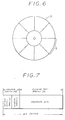
- the MSR disc suitable for recording and reproducing of high resolution can be recorded and/or reproduced by an ordinary magneto-optical disc drive apparatus according to a recording and/or reproducing system which will be described below with reference to FIGS. 6 and 7.
- the track area on a disc medium D is divided at every sector S of a proper length so that data can be processed at the unit of the sector S as shown in FIG. 6. Then, sector control informations such as a physical address on the disc D or the like are recorded on each sector S and the sector control information is written in advance in the disc as an emboss signal.
- FIG. 7 shows an ISO standard sector format of the WO (write once optical disc)/MO (erasable type optical disc).
- one sector is composed of a header portion HD and a recording data portion DA, and the header portion HD is recorded (pre-formatted) on the optical disc medium in advance as the emboss signal as earlier noted.
- the header portion HD is composed of a sector synchronizing (sync.) portion and an address portion.
- the sector sync. portion is used to relatively identify the interval between the sectors and sector control informations such as physical address on the disc or the like are recorded on the address portion.
- the physical address is composed of, for example, a track address and a sector address. In some cases, physical addresses might be sectors having serial numbers.
- the recording data is recorded only in the recording data portion DA in association with the sector control information of the header portion HD (associated information is stored in a directory area).
- the magneto-optical recording medium particularly, the magneto-optical recording medium of the front aperture detection type is arranged so as to read the recorded signal by changing the magnetization state of the reproducing layer in the playback mode, the magnetic characteristic thereof is changed at a relatively low temperature in such a manner that the magnetization is changed under a predetermined temperature condition. Accordingly, if the above magneto-optical recording medium is recorded and/or reproduced by the ordinary magneto-optical disc drive apparatus, the magnetic characteristic becomes unstable and a reproduced output is fluctuated. There is then the risk that the recorded signal cannot be played back precisely.
- the recording and/or reproducing apparatus of the MSR disc it is preferable that the MO disc, which is now widely and commercially available on the market, can be recorded and/or reproduced by this recording and/or reproducing apparatus.
- the recording and/or reproducing apparatus can commonly use the hardwares for recording and/or reproducing the above two discs, thereby being simplified in arrangement.
- EP-A-0 492 553 A2 describes a magneto-optical recording medium comprising an intermediate layer of TbFeCoCr having a Curie temperature of 130 °C
- EP-A-0 318 925 A3 describes a magneto-optical recording medium having an intermediate layer of DyFeCo with a Curie temperature of 93 °C.
- the magneto-optical recording medium 10 is the MSR disc of the front aperture detection type.
- a substrate 17 is made of a transparent material such as polycarbonate (PC) or the like.
- a dielectric layer 18 made of, for example, an SiN layer having a thickness of 800 ⁇ , a reproducing layer 11, an intermediate layer 12, a recording layer 13 and a surface protecting layer 19 having a thickness of 800 ⁇ by some suitable method such as the sputtering-process or the like, in that order.
- the revolution rate of the magneto-optical recording medium is 2400 r.p.m.
- a recording innermost periphery r is 30 mm
- an upper limit of environmental temperature is 50°C
- an upper limit of the laser output is 1.5 mW according to the standards of ISO (International Organization for Standardization).
- ISO International Organization for Standardization
- a Curie temperature T C2 of the intermediate layer 12 is selected to be 150°C or more so that, when this magneto-optical recording medium 10 is utilized in the ordinary magneto-optical disc drive apparatus, the temperature of the magneto-optical recording medium 10 can be avoided from rising more than the Curie temperature T C2 of the intermediate layer 12.
- the magnetizations of the respective magnetic layers, particularly, the magnetization of the intermediate layer 12 can be held reliably so that this MSR disc can be accurately and positively recorded and/or reproduced by the ordinary magneto-optical disc drive apparatus.
- the reproducing layer 11 is made of GdFeCo and 300 ⁇ in thickness
- the recording layer 13 is made of TbFeCo or the like and 400 ⁇ .
- the intermediate layer 12 is 200 ⁇ in thickness, for example, and the composition thereof is ⁇ Tb(Fe 0.95 Co 0.05 ) ⁇ 0.35 Al 0.05 of, for example, the TbfeCoAl system.
- the curie temperature T C2 thereof is selected to be 150°C.
- FIG. 9 shows a graph graphing the change of Curie temperature when z in (Tb 0.25 (Fe 0.95 CO 0.05 ) 0.75 ) 1-z Al z was changed. From FIG. 9, it can be understood that this Curie temperature T C2 is proper because the Curie temperature is lowered in proportion to the increase of the containing amount of Al in the TbFeCoAl system.
- FIG. 10 is a graph graphing the change of Curie temperature when z in (Tb 0.3 Fe 0.7 ) 1-z Al z was changed. As shown in FIG. 10, it can be appreciated that the Curie temperature is lowered in accordance with the increase of z , i.e., the containing amount of Al in the TbFeAl system. On the other hand, FIG. 10 is a graph graphing the change of Curie temperature when z in Tb 0.25 (Fe 1-z Co z ) 0.75 was changed. As shown in FIG. 10, it can be understood that the Curie temperature is lowered in proportion to the increase of the containing amount of Co. If the composition ratio of various materials is examined as described above, then it is possible to select the Curie temperature to be a predetermined one, i.e., 150°C or more.
- the Curie temperature Tc of the intermediate layer 12 is selected to be 150°C as described above, it is to be understood that this MSR disc can be normally recorded and/or reproduced by the ordinary magneto-optical disc drive apparatus.
- the present invention is not limited to the magneto-optical recording medium thus arranged and various modifications may be possible. If the present invention is applied to the magneto-optical recording medium of the MSR type serving as both rear aperture detection type and front aperture detection type which can achieve the playback of high resolution and in which the magnetic layer of the magneto-optical recording medium is formed as a four-layer structure formed of the reproducing layer 11, the reproducing auxiliary layer 91, the intermediate layer 12, the recording layer 13 or the like as, for example, shown in FIG.
- the magnetic characteristics can be prevented from being fluctuated at a relatively low temperature and the magneto-optical disc drive apparatus can produce a stable reproduced output, which can therefore effect the accurate and reliable recording and/or reproduction.
- the Curie temperature T C2 of the intermediate layer 12 is selected to be 150°C or more so that, even when this magneto-optical recording medium is utilized in the ordinary magneto-optical disc drive apparatus, the temperature of the magneto-optical recording medium 10 can be avoided from rising higher than the Curie temperature T C2 of the intermediate layer 12.
- the fluctuation of the reproduced output or the like due to the temperature dependence of the magnetic characteristics of the intermediate layer 12 can be avoided positively and the recording pit 4 of the recording layer 13 can be reliably held in the reproducing layer 11, which enables the magneto-optical recording medium of this invention to be recorded and/or reproduced even by the ordinary magneto-optical disc drive apparatus accurately and reliably.
Claims (2)
- Magnetooptisches Aufzeichnungsmedium (10) mit einer Aufzeichnungsschicht (13), einer Wiedergabeschicht (11) und einer Zwischenschicht (12) zur magnetischen Kopplung der Aufzeichnungsschicht (13) und der Wiedergabeschicht (11) in einem stationären Zustand, bei dem die magnetische Kopplung zwischen der Aufzeichnungsschicht (13) und der Wiedergabeschicht (11) in einem Bereich (14) fehlt, in dem die Temperatur derart erhöht wird, daß sie über einer bei der Wiedergabe durch die Lichteinstrahlung hervorgerufenen bestimmten Temperatur liegt und in dem eine in der Aufzeichnungsschicht (13) gespeicherte, aufgezeichnete Information aus der Wiedergabeschicht (11) in dem bestrahlten Bereich (5) mit Ausnahme des Bereichs (14) wiedergegeben wird, in dem die magnetische Kopplung fehlt und in dem die Curie-Temperatur der Zwischenschicht (12) auf 150°C oder darüber eingestellt wurde,
dadurch gekennzeichnet, daß die Zwischenschicht (12) aus TbFeCoAl oder TbFeAl zusammengesetzt ist. - Magnetooptisches Aufzeichnungsmedium (10) nach Anspruch (1), bei dem eine obere Begrenzung einer Ausgabeleistung des Lichtstrahls 1,5 mW ist und der Lichtstrahl bezüglich des magnetooptischen Aufzeichnungsmediums (10) in einer Geschwindigkeit von 1,2 m/sekbewegt wird, wobei die aufgezeichnete Information wiedergegeben wird.
Priority Applications (1)
| Application Number | Priority Date | Filing Date | Title |
|---|---|---|---|
| EP96113028A EP0747896B1 (de) | 1991-02-08 | 1992-02-07 | Magnetooptisches Aufzeichnungs- und/oder -wiedergabegerät |
Applications Claiming Priority (4)
| Application Number | Priority Date | Filing Date | Title |
|---|---|---|---|
| JP18070/91 | 1991-02-08 | ||
| JP1807091A JPH04255937A (ja) | 1991-02-08 | 1991-02-08 | 光磁気記録媒体 |
| JP4289091A JPH04259943A (ja) | 1991-02-15 | 1991-02-15 | 光磁気ディスクの記録再生装置 |
| JP42890/91 | 1991-02-15 |
Related Child Applications (1)
| Application Number | Title | Priority Date | Filing Date |
|---|---|---|---|
| EP96113028A Division EP0747896B1 (de) | 1991-02-08 | 1992-02-07 | Magnetooptisches Aufzeichnungs- und/oder -wiedergabegerät |
Publications (3)
| Publication Number | Publication Date |
|---|---|
| EP0498459A2 EP0498459A2 (de) | 1992-08-12 |
| EP0498459A3 EP0498459A3 (en) | 1993-10-13 |
| EP0498459B1 true EP0498459B1 (de) | 1998-04-22 |
Family
ID=26354690
Family Applications (2)
| Application Number | Title | Priority Date | Filing Date |
|---|---|---|---|
| EP96113028A Expired - Lifetime EP0747896B1 (de) | 1991-02-08 | 1992-02-07 | Magnetooptisches Aufzeichnungs- und/oder -wiedergabegerät |
| EP92102089A Expired - Lifetime EP0498459B1 (de) | 1991-02-08 | 1992-02-07 | Magnetooptisches Medium |
Family Applications Before (1)
| Application Number | Title | Priority Date | Filing Date |
|---|---|---|---|
| EP96113028A Expired - Lifetime EP0747896B1 (de) | 1991-02-08 | 1992-02-07 | Magnetooptisches Aufzeichnungs- und/oder -wiedergabegerät |
Country Status (3)
| Country | Link |
|---|---|
| US (1) | US5579294A (de) |
| EP (2) | EP0747896B1 (de) |
| DE (2) | DE69231042T2 (de) |
Families Citing this family (22)
| Publication number | Priority date | Publication date | Assignee | Title |
|---|---|---|---|---|
| JP2986622B2 (ja) * | 1992-09-02 | 1999-12-06 | シャープ株式会社 | 光磁気メモリー素子およびその記録再生方法 |
| US5699342A (en) * | 1994-02-07 | 1997-12-16 | Mitsubishi Denki Kabushiki Kaisha | Method of and device for recording and playing back an optical disk having a test playback region utilizing pits of minimum size for controlling the power of the laser |
| JPH07244876A (ja) * | 1994-03-01 | 1995-09-19 | Sharp Corp | 光磁気記録媒体及び光磁気記録再生方法 |
| US5568461A (en) * | 1994-04-20 | 1996-10-22 | Matsushita Electric Industrial Co., Ltd. | Optical information recording and reproducing apparatus |
| JPH0927154A (ja) * | 1995-07-10 | 1997-01-28 | Fujitsu Ltd | 光磁気ディスク装置 |
| DE69618722T2 (de) * | 1995-08-09 | 2002-08-22 | Sony Corp., Tokio/Tokyo | Aufzeichnungsmedium, Aufzeichnungsgerät und Wiedergabegerät |
| JP3424037B2 (ja) * | 1996-04-05 | 2003-07-07 | 富士通株式会社 | 光磁気記録媒体の情報再生方法及び情報記録方法、並びに光磁気再生装置 |
| US6049517A (en) * | 1996-04-30 | 2000-04-11 | Sony Corporation | Dual format audio signal compression |
| US6226233B1 (en) | 1996-07-30 | 2001-05-01 | Seagate Technology, Inc. | Magneto-optical system utilizing MSR media |
| US5982723A (en) * | 1996-09-30 | 1999-11-09 | Laser Dynamics, Inc. | Data recording and reproducing method for multi-layered optical disk system |
| US20050058039A1 (en) * | 1997-01-16 | 2005-03-17 | Yasuo Kamatani | Multi-standard optical disk and method and apparatus of reading from and recording to the disk |
| JP3615021B2 (ja) * | 1997-06-30 | 2005-01-26 | 富士通株式会社 | 光学的記憶装置及び光記憶媒体の記録再生方法 |
| US6847590B2 (en) * | 1997-07-04 | 2005-01-25 | Sanyo Electric Co., Ltd. | Magneto-optical recording medium including a calibration magnetic domain recorded in a predetermined pattern in a recording layer |
| JP3520183B2 (ja) * | 1997-07-04 | 2004-04-19 | 三洋電機株式会社 | 光磁気記録媒体の再生装置 |
| US6278667B1 (en) * | 1998-01-30 | 2001-08-21 | Seagate Technology, Inc. | System and method for light power control in a magneto-optical drive |
| JPH11283291A (ja) * | 1998-01-30 | 1999-10-15 | Fujitsu Ltd | 記憶装置、光学的記録媒体及び情報記録方法 |
| JP2000021039A (ja) * | 1998-06-30 | 2000-01-21 | Sony Corp | 再生装置及び再生方法 |
| JP3675340B2 (ja) * | 2001-01-26 | 2005-07-27 | ヤマハ株式会社 | 情報記録装置およびプログラム |
| US7317674B2 (en) * | 2003-03-11 | 2008-01-08 | Intersil Americas Inc. | Optical pick-up units and laser drivers with increased functionality |
| JP2007334992A (ja) * | 2006-06-15 | 2007-12-27 | Hitachi Ltd | 光ディスク再生装置および光ディスク再生方法 |
| US7813247B2 (en) | 2006-07-06 | 2010-10-12 | Intersil Americas Inc. | Hybrid laser diode drivers that include a decoder |
| US8018809B2 (en) * | 2007-05-16 | 2011-09-13 | Intersil Americas Inc. | Hybrid laser diode drivers |
Citations (4)
| Publication number | Priority date | Publication date | Assignee | Title |
|---|---|---|---|---|
| JPH0388156A (ja) * | 1989-08-31 | 1991-04-12 | Sony Corp | 光磁気記録再生方法 |
| EP0498461A2 (de) * | 1991-02-08 | 1992-08-12 | Sony Corporation | System und Verfahren zur Wiedergabe von Signalen aufgezeichnet auf einem magnetooptischer Aufzeichnungsmedium |
| EP0526641A1 (de) * | 1991-02-05 | 1993-02-10 | Sony Corporation | Verfahren zur Wiedergabe eines Signals aus einem optischen Aufzeichnungsmedium |
| EP0536404A1 (de) * | 1991-02-05 | 1993-04-14 | Sony Corporation | Verfahren zur wiedergabe eines signals aus einem optischen aufzeichnungsmedium |
Family Cites Families (14)
| Publication number | Priority date | Publication date | Assignee | Title |
|---|---|---|---|---|
| GB2110459B (en) * | 1982-11-08 | 1985-08-14 | Kokusai Denshin Denwa Co Ltd | Magneto-optical recording system |
| JPS6171472A (ja) * | 1984-09-14 | 1986-04-12 | Pioneer Electronic Corp | 記録デイスク演奏装置 |
| JP2647649B2 (ja) * | 1986-07-03 | 1997-08-27 | パイオニア株式会社 | 光ディスク記録方法 |
| EP0258978B1 (de) * | 1986-07-08 | 1998-10-07 | Canon Kabushiki Kaisha | Magnetoptisches Aufzeichnungsmedium mit der Möglichkeit des Überschreibens mit zwei oder mehr Magnetschichten und dieses Medium verwendende Aufzeichnungsmethode |
| JPS6358661A (ja) * | 1986-08-29 | 1988-03-14 | Mitsubishi Electric Corp | フロツピ−デイスクのタイプ識別回路 |
| EP0318925B1 (de) * | 1987-11-30 | 1994-04-20 | Sony Corporation | Methode zum optischen Abtasten eines Signals aus einem magneto-optischen Speichermedium |
| JPH01149246A (ja) * | 1987-12-04 | 1989-06-12 | Sony Corp | 光磁気記録媒体 |
| JP2708531B2 (ja) * | 1989-03-07 | 1998-02-04 | パイオニア株式会社 | ディスクプレーヤ |
| US5168482A (en) * | 1989-08-31 | 1992-12-01 | Sony Corporation | Magnetooptical recording and playback method employing multi-layer recording medium with record holding layer and playback layer |
| JPH0487069A (ja) * | 1990-07-31 | 1992-03-19 | Sony Corp | 光ディスク記録装置 |
| JPH04105284A (ja) * | 1990-08-24 | 1992-04-07 | Sony Corp | 光ディスク記録及び/又は再生装置 |
| JP2910250B2 (ja) * | 1990-12-27 | 1999-06-23 | ソニー株式会社 | 光磁気記録媒体 |
| JP2969963B2 (ja) * | 1990-12-28 | 1999-11-02 | ソニー株式会社 | 光磁気記録媒体における信号再生方法 |
| DE29617991U1 (de) * | 1996-10-16 | 1996-11-28 | Drebo Werkzeugfabrik Gmbh, 88361 Altshausen | Bohrervorsatz |
-
1992
- 1992-02-07 EP EP96113028A patent/EP0747896B1/de not_active Expired - Lifetime
- 1992-02-07 EP EP92102089A patent/EP0498459B1/de not_active Expired - Lifetime
- 1992-02-07 DE DE69231042T patent/DE69231042T2/de not_active Expired - Lifetime
- 1992-02-07 DE DE69225159T patent/DE69225159T2/de not_active Expired - Lifetime
-
1994
- 1994-09-01 US US08/299,544 patent/US5579294A/en not_active Expired - Lifetime
Patent Citations (4)
| Publication number | Priority date | Publication date | Assignee | Title |
|---|---|---|---|---|
| JPH0388156A (ja) * | 1989-08-31 | 1991-04-12 | Sony Corp | 光磁気記録再生方法 |
| EP0526641A1 (de) * | 1991-02-05 | 1993-02-10 | Sony Corporation | Verfahren zur Wiedergabe eines Signals aus einem optischen Aufzeichnungsmedium |
| EP0536404A1 (de) * | 1991-02-05 | 1993-04-14 | Sony Corporation | Verfahren zur wiedergabe eines signals aus einem optischen aufzeichnungsmedium |
| EP0498461A2 (de) * | 1991-02-08 | 1992-08-12 | Sony Corporation | System und Verfahren zur Wiedergabe von Signalen aufgezeichnet auf einem magnetooptischer Aufzeichnungsmedium |
Also Published As
| Publication number | Publication date |
|---|---|
| DE69231042T2 (de) | 2000-09-28 |
| EP0747896B1 (de) | 2000-05-10 |
| DE69231042D1 (de) | 2000-06-15 |
| EP0498459A2 (de) | 1992-08-12 |
| EP0498459A3 (en) | 1993-10-13 |
| DE69225159D1 (de) | 1998-05-28 |
| US5579294A (en) | 1996-11-26 |
| DE69225159T2 (de) | 1998-08-13 |
| EP0747896A1 (de) | 1996-12-11 |
Similar Documents
| Publication | Publication Date | Title |
|---|---|---|
| EP0747896B1 (de) | Magnetooptisches Aufzeichnungs- und/oder -wiedergabegerät | |
| EP0524745B1 (de) | Magneto-optisches Aufzeichnungsmedium worauf Aufzeichnung mit einer Überschreibfunktion durchgeführt wird | |
| US5168482A (en) | Magnetooptical recording and playback method employing multi-layer recording medium with record holding layer and playback layer | |
| US5241520A (en) | System and method of reproducing signals recorded on a magneto-optic recording medium | |
| US5659537A (en) | Magneto-optical recording medium and method of reproducing from same | |
| US5233578A (en) | Method of recording information on a recording medium having at least two magnetic layers | |
| EP0492581B1 (de) | Ausleseverfahren für ein magnetooptisches Aufzeichnungsmedium | |
| EP0619577A1 (de) | Magnetooptischer Aufzeichnungsträger und Verfahren zur Informationswiedergabe | |
| EP0586122B1 (de) | Magnetooptische Speichervorrichtung und Verfahren zur Informationsaufnahme und -wiedergabe | |
| JP3114204B2 (ja) | 光記録媒体の記録再生方法 | |
| US5208799A (en) | Magneto-optic recording method and magneto-optic recording/reproducing apparatus | |
| EP0524315A1 (de) | Verfahren zur wiedergabe von signalen in optischem aufzeichnungsmedium | |
| CA1320269C (en) | Magneto-optic recording structure and method | |
| EP0788099B1 (de) | System und Verfahren zur Wiedergabe von auf einem magnetooptischen Aufzeichungsmedium aufgezeichneten Signalen | |
| JPH05101471A (ja) | 光磁気記録再生方法 | |
| US5684764A (en) | Magneto-optical recording medium having a plurality of magnetic layers | |
| US5740153A (en) | Magneto-optical disk, optical pickup, and magneto-optical disk drive | |
| EP0499278B1 (de) | Verfahren zur Aufzeichnung von Sektor-Kontrolle-Information auf einer magneto-optischen Scheibe | |
| US5662988A (en) | Magneto-optical recording medium | |
| KR100308857B1 (ko) | 광자기기록매체및그기록방법과광자기기록장치 | |
| JPH06223420A (ja) | 光磁気記録媒体 | |
| EP0668585B1 (de) | Verfahren und System zur Informationsaufzeichnung auf ein magnetooptisches Aufzeichnungsmedium | |
| KR100201450B1 (ko) | 광자기기록매체 | |
| JP3572686B2 (ja) | 情報記録媒体及びその再生方法 | |
| JP2981063B2 (ja) | 光磁気ディスク及び光磁気再生装置 |
Legal Events
| Date | Code | Title | Description |
|---|---|---|---|
| PUAI | Public reference made under article 153(3) epc to a published international application that has entered the european phase |
Free format text: ORIGINAL CODE: 0009012 |
|
| AK | Designated contracting states |
Kind code of ref document: A2 Designated state(s): DE FR GB |
|
| PUAL | Search report despatched |
Free format text: ORIGINAL CODE: 0009013 |
|
| AK | Designated contracting states |
Kind code of ref document: A3 Designated state(s): DE FR GB |
|
| 17P | Request for examination filed |
Effective date: 19940318 |
|
| 17Q | First examination report despatched |
Effective date: 19950518 |
|
| GRAG | Despatch of communication of intention to grant |
Free format text: ORIGINAL CODE: EPIDOS AGRA |
|
| GRAG | Despatch of communication of intention to grant |
Free format text: ORIGINAL CODE: EPIDOS AGRA |
|
| GRAH | Despatch of communication of intention to grant a patent |
Free format text: ORIGINAL CODE: EPIDOS IGRA |
|
| GRAH | Despatch of communication of intention to grant a patent |
Free format text: ORIGINAL CODE: EPIDOS IGRA |
|
| GRAA | (expected) grant |
Free format text: ORIGINAL CODE: 0009210 |
|
| DX | Miscellaneous (deleted) | ||
| AK | Designated contracting states |
Kind code of ref document: B1 Designated state(s): DE FR GB |
|
| REF | Corresponds to: |
Ref document number: 69225159 Country of ref document: DE Date of ref document: 19980528 |
|
| ET | Fr: translation filed | ||
| PLBE | No opposition filed within time limit |
Free format text: ORIGINAL CODE: 0009261 |
|
| STAA | Information on the status of an ep patent application or granted ep patent |
Free format text: STATUS: NO OPPOSITION FILED WITHIN TIME LIMIT |
|
| 26N | No opposition filed | ||
| REG | Reference to a national code |
Ref country code: GB Ref legal event code: IF02 |
|
| REG | Reference to a national code |
Ref country code: GB Ref legal event code: 746 Effective date: 20091123 |
|
| PGFP | Annual fee paid to national office [announced via postgrant information from national office to epo] |
Ref country code: DE Payment date: 20110218 Year of fee payment: 20 Ref country code: FR Payment date: 20110302 Year of fee payment: 20 |
|
| PGFP | Annual fee paid to national office [announced via postgrant information from national office to epo] |
Ref country code: GB Payment date: 20110217 Year of fee payment: 20 |
|
| REG | Reference to a national code |
Ref country code: DE Ref legal event code: R071 Ref document number: 69225159 Country of ref document: DE |
|
| REG | Reference to a national code |
Ref country code: DE Ref legal event code: R071 Ref document number: 69225159 Country of ref document: DE |
|
| REG | Reference to a national code |
Ref country code: GB Ref legal event code: PE20 Expiry date: 20120206 |
|
| PG25 | Lapsed in a contracting state [announced via postgrant information from national office to epo] |
Ref country code: DE Free format text: LAPSE BECAUSE OF EXPIRATION OF PROTECTION Effective date: 20120208 |
|
| PG25 | Lapsed in a contracting state [announced via postgrant information from national office to epo] |
Ref country code: GB Free format text: LAPSE BECAUSE OF EXPIRATION OF PROTECTION Effective date: 20120206 |