EP0499311A1 - Transformator - Google Patents
Transformator Download PDFInfo
- Publication number
- EP0499311A1 EP0499311A1 EP92200301A EP92200301A EP0499311A1 EP 0499311 A1 EP0499311 A1 EP 0499311A1 EP 92200301 A EP92200301 A EP 92200301A EP 92200301 A EP92200301 A EP 92200301A EP 0499311 A1 EP0499311 A1 EP 0499311A1
- Authority
- EP
- European Patent Office
- Prior art keywords
- winding
- transformer
- capacitor
- leakage inductance
- windings
- Prior art date
- Legal status (The legal status is an assumption and is not a legal conclusion. Google has not performed a legal analysis and makes no representation as to the accuracy of the status listed.)
- Granted
Links
- 238000004804 winding Methods 0.000 claims abstract description 68
- 239000003990 capacitor Substances 0.000 claims abstract description 21
- 239000004020 conductor Substances 0.000 claims abstract description 14
- 239000000696 magnetic material Substances 0.000 claims abstract description 4
- 230000008878 coupling Effects 0.000 description 12
- 238000010168 coupling process Methods 0.000 description 12
- 238000005859 coupling reaction Methods 0.000 description 12
- 238000010586 diagram Methods 0.000 description 10
- 230000000694 effects Effects 0.000 description 5
- 230000009466 transformation Effects 0.000 description 5
- 238000010276 construction Methods 0.000 description 2
- 230000007423 decrease Effects 0.000 description 2
- 229910000859 α-Fe Inorganic materials 0.000 description 2
- ATJFFYVFTNAWJD-UHFFFAOYSA-N Tin Chemical compound [Sn] ATJFFYVFTNAWJD-UHFFFAOYSA-N 0.000 description 1
- 230000003247 decreasing effect Effects 0.000 description 1
- 230000004907 flux Effects 0.000 description 1
- 238000009413 insulation Methods 0.000 description 1
- 230000004048 modification Effects 0.000 description 1
- 238000012986 modification Methods 0.000 description 1
- 238000010079 rubber tapping Methods 0.000 description 1
Images
Classifications
-
- H—ELECTRICITY
- H01—ELECTRIC ELEMENTS
- H01F—MAGNETS; INDUCTANCES; TRANSFORMERS; SELECTION OF MATERIALS FOR THEIR MAGNETIC PROPERTIES
- H01F27/00—Details of transformers or inductances, in general
- H01F27/34—Special means for preventing or reducing unwanted electric or magnetic effects, e.g. no-load losses, reactive currents, harmonics, oscillations, leakage fields
- H01F27/38—Auxiliary core members; Auxiliary coils or windings
-
- H—ELECTRICITY
- H01—ELECTRIC ELEMENTS
- H01F—MAGNETS; INDUCTANCES; TRANSFORMERS; SELECTION OF MATERIALS FOR THEIR MAGNETIC PROPERTIES
- H01F17/00—Fixed inductances of the signal type
- H01F17/04—Fixed inductances of the signal type with magnetic core
- H01F17/06—Fixed inductances of the signal type with magnetic core with core substantially closed in itself, e.g. toroid
-
- H—ELECTRICITY
- H01—ELECTRIC ELEMENTS
- H01F—MAGNETS; INDUCTANCES; TRANSFORMERS; SELECTION OF MATERIALS FOR THEIR MAGNETIC PROPERTIES
- H01F30/00—Fixed transformers not covered by group H01F19/00
- H01F30/06—Fixed transformers not covered by group H01F19/00 characterised by the structure
- H01F30/16—Toroidal transformers
Definitions
- the invention relates to a transformer, comprising a core of a soft-magnetic material provided with a first winding and a second winding which is coupled thereto, each winding consisting of at least one wire-shaped conductor.
- the transformer in accordance with the invention is characterized in that there is provided a third winding which is coupled to the first winding and the second winding and which is provided with terminals which are interconnected by means of a capacitor.
- the effect of the leakage inductance in a given frequency range can be substantially eliminated by the effect of the capacitor.
- the capacitor may be assumed to be connected in series with the leakage inductance and a load connected to the second winding. In that case it is advantageous when the number of turns of the third winding equals that of the second winding.
- the capacitor then has its actual value in the series connection, rather than a value increased or decreased by transformation.
- a preferred embodiment of the transformer in accordance with the invention is characterized in that the conductors constituting the first, the second and the third winding are twisted over at least a part of their length. As is known per se, this step increases the coupling between the windings, so that on the one hand the leakage inductance to be compensated by means of the capacitor is minimized while on the other hand the capacitor is connected as effectively as possible in series with the leakage inductance and the load.
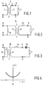
- Fig. 1 shows a circuit diagram of a known transformer 1, comprising a first winding 3 and a second winding 5 which are provided on a core 7 of a soft-magnetic material, for example ferrite.
- a load 11 is connected to the second winding 5 via output terminals 9.
- the first winding 3 is connected to input terminals 13.
- M is the mutual inductance of the two windings
- K is the coupling factor
- L1 and L2 are the inductance of the first and the second winding, respectively.
- K 1. In practice, however, K is always smaller than 1 because the coupling between the two windings is not perfect.
- the transformer 1 is shown as an ideal transformer 15, comprising a first winding 17 whereto a coil 19 having an inductance L1 is connected in parallel, and a second winding 21 with which a coil 23 is connected in series.
- the coil 23 represents the effect of the coupling factor K.
- Its inductance L s equals L2(1-K2). This is referred to as the leakage inductance.
- the ideal transformer 15 has a coupling factor K equal to 1 and a transformation ratio equal to L1/M : 1.
- the effect of the leakage inductance can in principle be reduced by connecting a suitable capacitor 25 in series with the coil 23 as indicated in the equivalent diagram of Fig. 3.
- the value C s of the capacitor 25 is chosen so that for a given frequency f0: For the frequency f0 the impedance measured across the input terminals 13 then equals R if the transformer 15 has a transformation ratio 1:1.
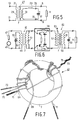
- Fig. 5 shows a diagram of a transformer 27 which does not have the described drawbacks.
- the transformer 27 comprises a third winding 33 which is provided with connection terminals 35 which are interconnected by means of a capacitor 37 which is preferably variable as shown.
- the coupling between the three windings 29, 31 and 33 is as high as possible, thus minimizing the leakage inductance.
- the capacitor 37 is connected to the third winding 33, it is not connected in series with the load 11 for low frequencies, so that the impedance measured across the input terminals 13 does not increase for low frequencies.
- the capacitor 37, the load 11 and the leakage inductance 23 may be assumed to be connected in series, so that for the frequency selected by adjustment of the value of the capacitor the impedance measured across the input terminals equals R (provided that the transformation ratio is 1:1). Thanks to the high coupling between the three windings, the value of the leakage inductance L s is very low, so that the circuit quality ⁇ 0L s /R is also very low. Consequently, the leakage inductance compensation introduced by the capacitor 37 is effective over a comparatively wide frequency range.
- Fig. 6 shows an example of a circuit utilizing two transformers whose leakage inductance is compensated for in the manner described with reference to Fig. 5.
- the circuit comprises a module 39 for a central antenna system which is coupled to the system via an input transformer 41 and an output transformer 43.
- the load 11 represents the outgoing cable system.
- the incoming antenna system is represented as a voltage source 45 having an internal impedance 47.
- the input transformer 41 comprises a primary winding 49, a secondary winding 51 and a compensation winding 53 whereto a variable capacitor 55 is connected.
- the transformation ratio is not equal to 1 (for example 6 : 5) and in order to reduce the leakage inductance the secondary winding is composed of two wire-shaped conductors in the manner described in the previous Netherlands Patent Application 90 02 005 (PHN 13.437).
- the compensation winding 53 comprises the same number of turns as the primary winding 49.
- the conductors constituting the windings are twisted over an as large as possible part of their length in order to maximize the coupling between the windings.
- the output transformer 43 comprises a primary winding 57, a secondary winding 59 and a compensation winding 61 whereto a variable capacitor 63 is connected.
- the secondary winding 59 and the compensation winding 61 comprise the same number of turns and the primary winding 57 consists of two series-connected sub-windings provided with a central tapping 65 whereto a direct voltage can be applied in order to power the module 39.
- the construction of the output transformer 43 is shown in Fig. 7.
- the output transformer 43 comprises a toroidal core 7 of ferrite on which four wire-shaped conductors 69, 71, 73 and 75 which have been twisted as far as possible are wound.
- the conductors 69 and 71 constitute the primary winding 57; the conductor 73 constitutes the secondary winding 59 and the conductor 75 constitutes the compensation winding 61.
- the insulation has been removed from the free ends of the conductors 69-75 and these ends have been coated with tin.
Landscapes
- Engineering & Computer Science (AREA)
- Power Engineering (AREA)
- Microelectronics & Electronic Packaging (AREA)
- Coils Or Transformers For Communication (AREA)
- Coils Of Transformers For General Uses (AREA)
- Charge And Discharge Circuits For Batteries Or The Like (AREA)
Applications Claiming Priority (2)
| Application Number | Priority Date | Filing Date | Title |
|---|---|---|---|
| NL9100247A NL9100247A (nl) | 1991-02-13 | 1991-02-13 | Transformator. |
| NL9100247 | 1991-02-13 |
Publications (2)
| Publication Number | Publication Date |
|---|---|
| EP0499311A1 true EP0499311A1 (de) | 1992-08-19 |
| EP0499311B1 EP0499311B1 (de) | 1995-08-16 |
Family
ID=19858869
Family Applications (1)
| Application Number | Title | Priority Date | Filing Date |
|---|---|---|---|
| EP92200301A Expired - Lifetime EP0499311B1 (de) | 1991-02-13 | 1992-02-04 | Transformator |
Country Status (6)
| Country | Link |
|---|---|
| US (1) | US5331271A (de) |
| EP (1) | EP0499311B1 (de) |
| JP (1) | JPH04317307A (de) |
| KR (1) | KR100217802B1 (de) |
| DE (1) | DE69204085T2 (de) |
| NL (1) | NL9100247A (de) |
Cited By (1)
| Publication number | Priority date | Publication date | Assignee | Title |
|---|---|---|---|---|
| WO2014047400A2 (en) | 2012-09-21 | 2014-03-27 | Ppc Broadband, Inc. | Radio frequency transformer winding coil structure |
Families Citing this family (11)
| Publication number | Priority date | Publication date | Assignee | Title |
|---|---|---|---|---|
| JPH0918222A (ja) * | 1995-06-28 | 1997-01-17 | Nippon Sheet Glass Co Ltd | 窓ガラスアンテナ装置 |
| US5929738A (en) * | 1997-06-16 | 1999-07-27 | Thomas & Betts International, Inc. | Triple core toroidal transformer |
| DE10260246B4 (de) * | 2002-12-20 | 2006-06-14 | Minebea Co., Ltd. | Spulenanordnung mit veränderbarer Induktivität |
| KR100542245B1 (ko) * | 2003-12-23 | 2006-01-11 | 한국표준과학연구원 | 전자보상 계기용 변류기 |
| EP2052436B1 (de) | 2006-09-15 | 2014-10-29 | Halliburton Energy Services, Inc. | Multiaxialantenne und anwendungsmethode in extraktionswerkzeugen |
| KR101714507B1 (ko) * | 2008-05-22 | 2017-03-09 | 삼성전자주식회사 | 발룬 회로 및 노치 필터를 포함하는 수신회로 및 동작 방법 |
| WO2012015942A1 (en) * | 2010-07-27 | 2012-02-02 | Georgia Tech Research Corporation | Systems and methods for providing ac/dc boost converters for energy harvesting |
| US20140266536A1 (en) * | 2013-03-15 | 2014-09-18 | Lantek Electronics Inc. | Ferrite core winding structure with high frequency response |
| US10270401B2 (en) | 2014-10-20 | 2019-04-23 | Richwave Technology Corp. | Two-stage electromagnetic induction transformer |
| TWI532064B (zh) * | 2014-10-20 | 2016-05-01 | 立積電子股份有限公司 | 變壓器、射頻放大器及藉由變壓器以提供阻抗匹配的方法 |
| JP7663194B2 (ja) * | 2021-03-29 | 2025-04-16 | Necネットワーク・センサ株式会社 | フラックスゲート型磁気検出器 |
Family Cites Families (9)
| Publication number | Priority date | Publication date | Assignee | Title |
|---|---|---|---|---|
| CA476112A (en) * | 1951-08-14 | Hendrik Gusdorf Frederik | Inductively coupled circuits | |
| US1133750A (en) * | 1913-09-29 | 1915-03-30 | American Telephone & Telegraph | Transformer. |
| US1591660A (en) * | 1924-10-28 | 1926-07-06 | Cory Harvey | Radioreception |
| FR627866A (fr) * | 1926-01-23 | 1927-10-14 | Secheron Atel | Transformateur de soudage à arc, de puissance apparente absorbée réduite |
| FR786439A (fr) * | 1934-03-14 | 1935-09-03 | Philips Nv | Transformateur électrique pour courants à basse fréquence |
| US2992386A (en) * | 1958-08-01 | 1961-07-11 | Forbro Design Inc | Power supply with adjustable stabilized output voltage |
| US4339706A (en) * | 1975-05-29 | 1982-07-13 | Jodice Controls Corporation | Current controlling |
| JPS6013565B2 (ja) * | 1977-12-01 | 1985-04-08 | パイオニア株式会社 | 自動利得制御回路 |
| JPS57196509A (en) * | 1981-05-29 | 1982-12-02 | Toshiba Corp | Transformer for switching regulator |
-
1991
- 1991-02-13 NL NL9100247A patent/NL9100247A/nl not_active Application Discontinuation
-
1992
- 1992-02-04 EP EP92200301A patent/EP0499311B1/de not_active Expired - Lifetime
- 1992-02-04 DE DE69204085T patent/DE69204085T2/de not_active Expired - Lifetime
- 1992-02-07 KR KR1019920001734A patent/KR100217802B1/ko not_active Expired - Lifetime
- 1992-02-10 JP JP4023797A patent/JPH04317307A/ja active Pending
-
1993
- 1993-03-10 US US08/029,289 patent/US5331271A/en not_active Expired - Lifetime
Non-Patent Citations (1)
| Title |
|---|
| PATENT ABSTRACTS OF JAPAN vol. 7, no. 45 (E-160)(1190) 23 February 1983 & JP-A-57 196 509 ( TOKYO SHIBAURA DENKI K.K. ) 2 December 1982 * |
Cited By (5)
| Publication number | Priority date | Publication date | Assignee | Title |
|---|---|---|---|---|
| WO2014047400A2 (en) | 2012-09-21 | 2014-03-27 | Ppc Broadband, Inc. | Radio frequency transformer winding coil structure |
| CN105122395A (zh) * | 2012-09-21 | 2015-12-02 | Ppc宽带公司 | 射频变压器卷绕线圈结构 |
| EP2898517A4 (de) * | 2012-09-21 | 2016-09-07 | Ppc Broadband Inc | Windungsspulenstruktur für einen funkfrequenztransformator |
| US9953756B2 (en) | 2012-09-21 | 2018-04-24 | Ppc Broadband, Inc. | Radio frequency transformer winding coil structure |
| US10796839B2 (en) | 2012-09-21 | 2020-10-06 | Ppc Broadband, Inc. | Radio frequency transformer winding coil structure |
Also Published As
| Publication number | Publication date |
|---|---|
| EP0499311B1 (de) | 1995-08-16 |
| KR100217802B1 (ko) | 1999-09-01 |
| US5331271A (en) | 1994-07-19 |
| KR920017140A (ko) | 1992-09-26 |
| DE69204085T2 (de) | 1996-03-21 |
| DE69204085D1 (de) | 1995-09-21 |
| JPH04317307A (ja) | 1992-11-09 |
| NL9100247A (nl) | 1992-09-01 |
Similar Documents
| Publication | Publication Date | Title |
|---|---|---|
| US7567162B2 (en) | Apparatus and method for winding an energy transfer element core | |
| US6577219B2 (en) | Multiple-interleaved integrated circuit transformer | |
| US2553324A (en) | Wide band audio and video transformer | |
| EP0499311B1 (de) | Transformator | |
| US8324999B2 (en) | High frequency transformer for high voltage applications | |
| US6750752B2 (en) | High power wideband balun and power combiner/divider incorporating such a balun | |
| US6664881B1 (en) | Efficient, low leakage inductance, multi-tap, RF transformer and method of making same | |
| EP1166440B1 (de) | Transformator mit ubermittlungsleitung für impedanzanpassung | |
| EA000368B1 (ru) | Широкополосная трансформаторная схема с высоким коэффициентом трансформации импедансов | |
| EP0410526A1 (de) | Generator zum Erzeugen einer elektrischen Spannung | |
| CA2240768C (en) | Triple core toroidal transformer | |
| US5309120A (en) | RF high power, high frequency, non-integer turns ratio bandpass auto-transformer and method | |
| RU2143784C1 (ru) | Широкополосное устройство присоединения с направленными свойствами | |
| KR102945658B1 (ko) | 다중연결 구조의 초고주파 파워회로 | |
| US20010026459A1 (en) | Transformer | |
| JPH03296313A (ja) | 電力線搬送通信用の単相三線式ブロッキングフィルタ | |
| JPS5840808A (ja) | 平衡−平衡形変成器 | |
| SU457109A1 (ru) | Импульсный трансформатор | |
| JP2000357977A (ja) | 複同調トランス | |
| JPH1168498A (ja) | インピーダンス変換回路 | |
| KR20020007098A (ko) | 완전결합 변압기를 이용한 고주파 전원 장치 | |
| KR19990073377A (ko) | 3상단권변압기 | |
| JP2001024481A (ja) | 複同調トランス | |
| RU93017288A (ru) | Трансформатор для сварки | |
| JPS61125214A (ja) | 分岐回路 |
Legal Events
| Date | Code | Title | Description |
|---|---|---|---|
| PUAI | Public reference made under article 153(3) epc to a published international application that has entered the european phase |
Free format text: ORIGINAL CODE: 0009012 |
|
| AK | Designated contracting states |
Kind code of ref document: A1 Designated state(s): DE FR GB IT |
|
| 17P | Request for examination filed |
Effective date: 19930215 |
|
| 17Q | First examination report despatched |
Effective date: 19930831 |
|
| RHK1 | Main classification (correction) |
Ipc: H01F 30/10 |
|
| GRAA | (expected) grant |
Free format text: ORIGINAL CODE: 0009210 |
|
| AK | Designated contracting states |
Kind code of ref document: B1 Designated state(s): DE FR GB IT |
|
| PG25 | Lapsed in a contracting state [announced via postgrant information from national office to epo] |
Ref country code: IT Free format text: LAPSE BECAUSE OF FAILURE TO SUBMIT A TRANSLATION OF THE DESCRIPTION OR TO PAY THE FEE WITHIN THE PRE;WARNING: LAPSES OF ITALIAN PATENTS WITH EFFECTIVE DATE BEFORE 2007 MAY HAVE OCCURRED AT ANY TIME BEFORE 2007. THE CORRECT EFFECTIVE DATE MAY BE DIFFERENT FROM THE ONE RECORDED.SCRIBED TIME-LIMIT Effective date: 19950816 Ref country code: FR Free format text: THE PATENT HAS BEEN ANNULLED BY A DECISION OF A NATIONAL AUTHORITY Effective date: 19950816 |
|
| REF | Corresponds to: |
Ref document number: 69204085 Country of ref document: DE Date of ref document: 19950921 |
|
| EN | Fr: translation not filed | ||
| PG25 | Lapsed in a contracting state [announced via postgrant information from national office to epo] |
Ref country code: GB Effective date: 19960204 |
|
| PLBE | No opposition filed within time limit |
Free format text: ORIGINAL CODE: 0009261 |
|
| STAA | Information on the status of an ep patent application or granted ep patent |
Free format text: STATUS: NO OPPOSITION FILED WITHIN TIME LIMIT |
|
| 26N | No opposition filed | ||
| GBPC | Gb: european patent ceased through non-payment of renewal fee |
Effective date: 19960204 |
|
| PGFP | Annual fee paid to national office [announced via postgrant information from national office to epo] |
Ref country code: DE Payment date: 20110208 Year of fee payment: 20 |
|
| REG | Reference to a national code |
Ref country code: DE Ref legal event code: R071 Ref document number: 69204085 Country of ref document: DE |
|
| REG | Reference to a national code |
Ref country code: DE Ref legal event code: R071 Ref document number: 69204085 Country of ref document: DE |
|
| PG25 | Lapsed in a contracting state [announced via postgrant information from national office to epo] |
Ref country code: DE Free format text: LAPSE BECAUSE OF EXPIRATION OF PROTECTION Effective date: 20120205 |