EP0499760B1 - Kessel und Anlage für eine Zentralheizung und/oder Warmwassererzeugung - Google Patents
Kessel und Anlage für eine Zentralheizung und/oder Warmwassererzeugung Download PDFInfo
- Publication number
- EP0499760B1 EP0499760B1 EP19910440010 EP91440010A EP0499760B1 EP 0499760 B1 EP0499760 B1 EP 0499760B1 EP 19910440010 EP19910440010 EP 19910440010 EP 91440010 A EP91440010 A EP 91440010A EP 0499760 B1 EP0499760 B1 EP 0499760B1
- Authority
- EP
- European Patent Office
- Prior art keywords
- combustion
- boiler
- tubes
- heating body
- fumes
- Prior art date
- Legal status (The legal status is an assumption and is not a legal conclusion. Google has not performed a legal analysis and makes no representation as to the accuracy of the status listed.)
- Expired - Lifetime
Links
Images

Classifications
-
- F—MECHANICAL ENGINEERING; LIGHTING; HEATING; WEAPONS; BLASTING
- F24—HEATING; RANGES; VENTILATING
- F24H—FLUID HEATERS, e.g. WATER OR AIR HEATERS, HAVING HEAT-GENERATING MEANS, e.g. HEAT PUMPS, IN GENERAL
- F24H1/00—Water heaters, e.g. boilers, continuous-flow heaters or water-storage heaters
- F24H1/48—Water heaters for central heating incorporating heaters for domestic water
- F24H1/52—Water heaters for central heating incorporating heaters for domestic water incorporating heat exchangers for domestic water
-
- F—MECHANICAL ENGINEERING; LIGHTING; HEATING; WEAPONS; BLASTING
- F24—HEATING; RANGES; VENTILATING
- F24H—FLUID HEATERS, e.g. WATER OR AIR HEATERS, HAVING HEAT-GENERATING MEANS, e.g. HEAT PUMPS, IN GENERAL
- F24H1/00—Water heaters, e.g. boilers, continuous-flow heaters or water-storage heaters
- F24H1/22—Water heaters other than continuous-flow or water-storage heaters, e.g. water heaters for central heating
- F24H1/34—Water heaters other than continuous-flow or water-storage heaters, e.g. water heaters for central heating with water chamber arranged adjacent to the combustion chamber or chambers, e.g. above or at side
- F24H1/36—Water heaters other than continuous-flow or water-storage heaters, e.g. water heaters for central heating with water chamber arranged adjacent to the combustion chamber or chambers, e.g. above or at side the water chamber including one or more fire tubes
Definitions
- the invention relates to a boiler and to a central heating and / or domestic hot water production installation. It will find its application in particular in the manufacturers of domestic or industrial heating appliances.
- a traditional boiler mainly comprises three parts which can be summarized in a hearth at the base, an intermediate heating body and a flue gas exhaust at the top.
- the hearth itself consists in particular of gas burners, and a combustion chamber.
- the fumes from combustion generally reach a temperature between 1,000 and 1,200 ° C from which a maximum of calories must be removed. It is the role of the heating body which serves as a heat exchanger between the combustion fumes and a heat transfer fluid which is very often water.
- the heating body may include one or more heat transfer fluid circuits, in domestic applications very often, two circuits are encountered, a heating circuit and a hot water circuit.
- the temperature of the fumes must have decreased appreciably and an attempt is made to reach approximately 200 ° C. They are evacuated by the flue evacuation pipe.
- the heating body In the case of boilers with an independent double heating circuit, the heating body consists of an outer casing terminated, at each upper and lower end, by an upper and lower flange through which open tubes capable of being traversed by the combustion fumes.
- the envelope is waterproof and contains the heat transfer fluid which is used for heating. Between the smoke tubes, if necessary, there is a coil which is used for heating hot water sanitary.
- the number and section of the smoke tubes must be determined by the manufacturer to obtain maximum recovery of the calories present in the smoke gases.
- the smoke tubes generally contain turbulators whose role is to slow the speed of passage of gases within the smoke tubes.
- the efficiency of a boiler depends on the ability of the heating body to recover the maximum number of calories present in the flue gases. At this level, compromises must be made because, for example, an exchanger, which recovers calories, for a small part by radiation, and for the rest by convection, should have a path for very long smoke with a reduced speed of passage, to recover the maximum of calories. In return, if the smoke is evacuated in poor draft conditions, then there is a poor combustion efficiency with a large percentage of unburnt fuels.
- Document FR-A-2,233,572 discloses a gas boiler comprising a combustion chamber, a heating body, as well as a smoke evacuation zone, capable of being connected to a smoke evacuation duct.
- Said heating body consists of a sealed outer envelope through which are arranged tubes, traversed by the combustion fumes, which have a decreasing section in the direction of the heat flow.
- this boiler has a configuration particularly so that the burner flames can enter further into the tubes so that most of the combustion takes place in the combustion chamber.
- One of the determining points is the temperature of the flame which itself depends on the intake of secondary air.
- primary combustion air is defined as the combustion air which is introduced into the burner itself to be mixed with the fuel whereas the secondary air is the air present in the combustion chamber surrounding the flames.
- the main object of the present invention is to present a boiler, the efficiency of which in terms of heat exchange is preserved compared to existing devices, capable of withstanding high overload conditions specific to the different standards and moreover capable of improving combustion hygienes with reduction of carbon monoxide and nitrogen oxide emissions.
- the heating body of the present invention makes it possible to reconcile totally divergent requirements in terms of heat exchange efficiency and speed of evacuation of combustion fumes.
- the boiler comprising a combustion chamber, a heating body, as well as a smoke activity zone, capable of being connected to a smoke evacuation duct, said heating body being constituted of a sealed outer envelope through which are arranged tubes traversed by the combustion fumes, which have a decreasing section in the direction of the flow of combustion fumes, is characterized in that the said tubes are equipped in their lower part with 'tubular appendices on the one hand opening into the combustion chamber and, on the other hand, connected to the smoke tubes.
- the boiler of the present invention uses gas as fuel. Furthermore, the boiler of the present invention is particularly intended for a central heating installation and / or for producing domestic hot water.
- the present invention relates to a boiler as well as a central heating installation and / or domestic hot water production. She will find in particular its application in the manufacturers of domestic or industrial heating appliances.
- the invention has been more specifically developed in the context of gas boilers, however it may very simply extend to boilers using other types of fuel.
- the role of a heating body is to recover the calories present in the combustion gases in order to transfer them to one or more circuits of heat transfer fluid.
- the efficiency of a boiler depends partly on the good conditions under which combustion can take place and on the other hand on the ability of the heating body to take up the calories present in the combustion gases.
- the technical requirements to be met in order to achieve good efficiency are contrary. It is necessary to reduce as much as possible the evacuation speed of the fumes to increase the heat exchange time.
- the temperature of the flue gases at the inlet is 1,000 to 1,200 ° C and it is 200 ° C at the outlet of the heating body.
- Most of the heat is exchanged by convection, and the flue tubes are generally fitted with turbulators to slow down the evacuation speed of the fumes and promote the transfer of calories.
- Figure 1 shows schematically in section the main components of a boiler, for example gas. At the base are burners 1, placed in a combustion chamber 2 which emits the fumes at a temperature of around 1,000 to 1,200 ° C. It is a traditional design of the boiler known to those skilled in the art.
- the boiler has a combustion gas evacuation zone.
- an anti-backflow draft cup 3 is placed above the central heating body 4, the said cup is used to recover the smoke emissions leaving the heating body 4 and to direct them towards a discharge duct for the smoke not shown.
- This is again a traditional organ, the production of which is known to those skilled in the art.
- the heating body 4 which is the subject of the present invention, is presented externally in a similar manner to a traditional heating body.
- this heating body 4 contains two independent circuits with heat transfer fluid, such as in particular water, namely: it is a heating circuit 5 and a domestic hot water circuit 6.
- the heating body 4 is composed of an outer casing 7 terminated at each upper and lower end respectively by an upper flange 8 and a lower flange 9 through which open vertical tubes 10, capable of being traversed by the combustion gases.
- the envelope 7 is sealed and contains the heat transfer fluid for the heating circuit 5.
- the heat transfer fluid for the heating circuit 5 With regard to domestic hot water with the circuit 6, the latter is arranged in the heating body in the form of a coil 11 wound around the smoke tubes 10. Turbulators shown diagrammatically in FIG. 1 in dotted lines 12 are placed in the smoke tubes 10 to brake the gases and increase the heat exchange between the heat transfer fluids and the combustion fumes.
- the boiler has means for increasing the circulation of smoke in the lower part of the heating body 4. This has a direct influence on the combustion operating conditions.
- the speed of passage of the combustion gases is lowered in the lower region of the heating body, that is to say where the transfer of calories takes place under good conditions due to the high temperature difference. Then, the speed of circulation of the fumes is reflected in the upper part of the heating body, where, to obtain a good heat exchange, it is precisely necessary to slow down the speed to increase the time of exchange.
- the means for increasing the circulation of the fumes in the lower part of the heating body play a favorable role both in terms of the operation of the heat exchange and to promote good combustion at the level of the burners 1.
- the means are, for example, in the form of an increase in the cross section of the smoke in the lower part of the heating body 4.
- smoke tubes 10 having a convergent sectional profile can be used.
- This simple solution is not, however, preferential since it does not allow an improvement in the temperature distribution along the smoke tube.
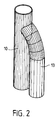
- FIG. 2 diagrams precisely the connection of an appendage 13 to a smoke tube 10.
- the appendages 13 do not include interior turbulators. This makes it possible to inject, at a certain height of the smoke tubes 10, hot combustion gases taken directly from the combustion chamber. This has two advantages: on the one hand, it facilitates the evacuation of the combustion gases, hence a better yield and less pollution, on the other hand, the temperature distribution in the smoke tube is improved.
- the temperature has been reduced in a non-proportional manner in the smoke tube, and with appendix 13 of the present invention.
- the efficiency of the heat exchange is thereby increased since the area with a large temperature difference is increased.
- connection height of the appendages 13 on the smoke tubes 10 must be determined by the manufacturer as a function of the geometry of the heating body.
- connection height is approximately 100 mm, one fifth of the height of the heating body. Increasing this value, up to 200 mm, the characteristics remain unchanged. Beyond this, there would be a decrease in the efficiency of the heating body because part of the combustion gases would pass too quickly.
- a lower connection height for example of 50 mm, reduces the efficiency of the draft.
- the heating body acts as a bottleneck for the draft and the secondary air intake cannot be controlled precisely.
- the evacuation of the fumes takes place under good conditions through the heating body and it is possible to regulate the admission of secondary air precisely, for example by rolling. .
- This regulation allows a lowering of the flame temperatures and is also accompanied by a rapid evacuation of the flue gases resulting in more limited nitrogen oxide emissions.
- the coil 11 for domestic hot water is disposed above the appendages 13 and therefore there is no mutual discomfort.
Landscapes
- Engineering & Computer Science (AREA)
- Physics & Mathematics (AREA)
- Thermal Sciences (AREA)
- Chemical & Material Sciences (AREA)
- Combustion & Propulsion (AREA)
- Mechanical Engineering (AREA)
- General Engineering & Computer Science (AREA)
Claims (7)
- Heizkessel, umfassend eine Verbrennungskammer (2), einen Heizkörper (4), sowie einen Rauchtätigkeitsbereich (3), der geeignet ist, mit einem Rauchabfuhrkanal verbunden zu werden, wobei der genannte Heizkörper (4) aus einem dichten Außenmantel (7) besteht, durch den hindurch von den Verbrennungsrauchen durchströmte Rohre (10) angeordnet sind, die einen in Richtung der Verbrennungsrauchströmung abnehmenden Querschnitt aufweisen, dadurch gekennzeichnet, daß die genannten Rohre (10) an deren unteren Teil mit rohrförmigen Ansätzen (13) versehen sind, die, einerseits, in die Verbrennungskammer (2) enden und, andererseits, an den Rauchrohren (10) angeschlossen sind.
- Heizkessel nach Anspruch 1, dadurch gekennzeichnet, daß die Rauchrohre (10) mit Wirbelstromerzeugern (12) ausgestattet sind und die Ansätze (13) keine Wirbelstromerzeuger umfassen.
- Heizkessel nach Anspruch 1, dadurch gekennzeichnet, daß sich die Ansätze (13) auf etwa 1/5 deren Höhe an die Hauptrauchrohre (10) anschließen.
- Heizkessel nach Anspruch 1, dadurch gekennzeichnet, daß sich die Ansätze (13) auf verschiedenen Höhen an die Hauptrauchrohre (10) anschließen.
- Heizkessel nach irgendeinem der vorgehenden Ansprüche, der Gas als Brennstoff verwendet.
- Zentralheizungsanlage, die mit einem Heizkessel nach einem der Ansprüche 1 bis 5 ausgerüstet ist.
- Zentralheizungs- und Sanitärheißwasserproduktionsanlage, die mit einem Heizkessel nach einem der Ansprüche 1 bis 5 ausgerüstet ist.
Priority Applications (2)
| Application Number | Priority Date | Filing Date | Title |
|---|---|---|---|
| DE1991602760 DE69102760T2 (de) | 1991-02-13 | 1991-02-13 | Kessel und Anlage für eine Zentralheizung und/oder Warmwassererzeugung. |
| AT91440010T ATE108265T1 (de) | 1991-02-13 | 1991-02-13 | Kessel und anlage für eine zentralheizung und/oder warmwassererzeugung. |
Applications Claiming Priority (1)
| Application Number | Priority Date | Filing Date | Title |
|---|---|---|---|
| FR9001620A FR2657951B1 (fr) | 1990-02-02 | 1990-02-02 | Chaudiere et installation de chauffage central et/ou de production d'eau chaude sanitaire. |
Publications (2)
| Publication Number | Publication Date |
|---|---|
| EP0499760A1 EP0499760A1 (de) | 1992-08-26 |
| EP0499760B1 true EP0499760B1 (de) | 1994-07-06 |
Family
ID=9393607
Family Applications (1)
| Application Number | Title | Priority Date | Filing Date |
|---|---|---|---|
| EP19910440010 Expired - Lifetime EP0499760B1 (de) | 1990-02-02 | 1991-02-13 | Kessel und Anlage für eine Zentralheizung und/oder Warmwassererzeugung |
Country Status (2)
| Country | Link |
|---|---|
| EP (1) | EP0499760B1 (de) |
| FR (1) | FR2657951B1 (de) |
Families Citing this family (3)
| Publication number | Priority date | Publication date | Assignee | Title |
|---|---|---|---|---|
| CN102022821B (zh) * | 2010-12-22 | 2013-04-03 | 曲沃县秀水炉业有限公司 | 一种立式燃气锅炉 |
| CN113686017B (zh) * | 2021-09-08 | 2022-12-16 | 国家能源集团乐东发电有限公司 | 一种锅炉余热利用装置 |
| CN114909804B (zh) * | 2022-03-02 | 2025-07-11 | 浙江先创能源科技股份有限公司 | 一种串联变流速逆流换热的燃气导热油锅炉 |
Family Cites Families (2)
| Publication number | Priority date | Publication date | Assignee | Title |
|---|---|---|---|---|
| DE1934764U (de) * | 1965-02-05 | 1966-03-17 | Michel Dellacroce | Zentralheizungsblock mit eingebautem heizoelbehaelter. |
| CH567233A5 (de) * | 1973-06-15 | 1975-09-30 | Ygnis Sa |
-
1990
- 1990-02-02 FR FR9001620A patent/FR2657951B1/fr not_active Expired - Fee Related
-
1991
- 1991-02-13 EP EP19910440010 patent/EP0499760B1/de not_active Expired - Lifetime
Also Published As
| Publication number | Publication date |
|---|---|
| FR2657951B1 (fr) | 1995-08-04 |
| EP0499760A1 (de) | 1992-08-26 |
| FR2657951A1 (fr) | 1991-08-09 |
Similar Documents
| Publication | Publication Date | Title |
|---|---|---|
| FR2640357A1 (fr) | Bruleur a gaz empechant une combustion incomplete | |
| EP0499760B1 (de) | Kessel und Anlage für eine Zentralheizung und/oder Warmwassererzeugung | |
| WO2005059440A1 (fr) | Procede de combustion etagee avec injection optimisee de l'oxydant primaire | |
| CA1123285A (fr) | Procede de combustion d'un combustible liquide et bruleur pour sa mise en oeuvre | |
| EP0850883A2 (de) | Verfahren zur Herstellung von technischem Glas und Brenner zur Durchführung des Verfahrens | |
| KR101319950B1 (ko) | 가열 장치 | |
| BE1006124A6 (fr) | Plan de cuisson a grand rendement et combustion amelioree. | |
| BE1005472A3 (fr) | Bruleur ameliore, particulierement approprie pour chauffe-eau pour montage mural. | |
| EP0775868B1 (de) | Gasbrenner für Aufwärmöfen für siderurgische Produkte | |
| CN2476728Y (zh) | 红外线和大气式组合灶具 | |
| FR2749927A1 (fr) | Bruleur a faible niveau d'emission de composes polluants | |
| FR2895490A1 (fr) | Procede d'oxycombustion etagee mettant en oeuvre des reactifs prechauffes | |
| JP2529699B2 (ja) | ボイラの低騒音燃焼方法 | |
| FR2481781A1 (fr) | Equipement du type boite de foyer pour fours ou chaudieres et dispositif pour son maintien | |
| JPH07233920A (ja) | 酸素バーナの燃焼方法 | |
| FR2491593A1 (fr) | Chaudiere de chauffage pour la combustion de combustible solide et procede pour sa mise en oeuvre | |
| RU2090800C1 (ru) | Горелка для твердого топлива с факельной трубкой | |
| JPH09229368A (ja) | こんろ | |
| FR2710727A1 (fr) | Dispositif de prélèvement de calories pour flamme de brûleur à gaz fonctionnant en milieu confié, brûleur en faisant application et installation de chauffage par rayonnement le mettant en Óoeuvre. | |
| FR2636124A1 (fr) | Chaudiere de chauffage comportant des moyens pour renvoyer une partie des fumees au bruleur | |
| FR2714150A1 (fr) | Tête de combustion pour brûleur à faible émission de polluants et chaudière équipée d'un tel brûleur.. | |
| JPH07318003A (ja) | 多管式貫流ボイラ | |
| CN2215078Y (zh) | 取暖炉 | |
| BE475610A (de) | ||
| JPS6324352Y2 (de) |
Legal Events
| Date | Code | Title | Description |
|---|---|---|---|
| PUAI | Public reference made under article 153(3) epc to a published international application that has entered the european phase |
Free format text: ORIGINAL CODE: 0009012 |
|
| 17P | Request for examination filed |
Effective date: 19920224 |
|
| AK | Designated contracting states |
Kind code of ref document: A1 Designated state(s): AT BE CH DE DK ES GB GR IT LI LU NL SE |
|
| 17Q | First examination report despatched |
Effective date: 19920813 |
|
| GRAA | (expected) grant |
Free format text: ORIGINAL CODE: 0009210 |
|
| AK | Designated contracting states |
Kind code of ref document: B1 Designated state(s): AT BE CH DE DK ES GB GR IT LI LU NL SE |
|
| PG25 | Lapsed in a contracting state [announced via postgrant information from national office to epo] |
Ref country code: NL Effective date: 19940706 Ref country code: GR Free format text: LAPSE BECAUSE OF FAILURE TO SUBMIT A TRANSLATION OF THE DESCRIPTION OR TO PAY THE FEE WITHIN THE PRESCRIBED TIME-LIMIT Effective date: 19940706 Ref country code: ES Free format text: THE PATENT HAS BEEN ANNULLED BY A DECISION OF A NATIONAL AUTHORITY Effective date: 19940706 Ref country code: DK Effective date: 19940706 Ref country code: AT Effective date: 19940706 |
|
| REF | Corresponds to: |
Ref document number: 108265 Country of ref document: AT Date of ref document: 19940715 Kind code of ref document: T |
|
| REF | Corresponds to: |
Ref document number: 69102760 Country of ref document: DE Date of ref document: 19940811 |
|
| ITF | It: translation for a ep patent filed | ||
| PG25 | Lapsed in a contracting state [announced via postgrant information from national office to epo] |
Ref country code: SE Effective date: 19941006 |
|
| GBT | Gb: translation of ep patent filed (gb section 77(6)(a)/1977) |
Effective date: 19940915 |
|
| NLV1 | Nl: lapsed or annulled due to failure to fulfill the requirements of art. 29p and 29m of the patents act | ||
| PG25 | Lapsed in a contracting state [announced via postgrant information from national office to epo] |
Ref country code: LU Free format text: LAPSE BECAUSE OF NON-PAYMENT OF DUE FEES Effective date: 19950228 Ref country code: LI Effective date: 19950228 Ref country code: CH Effective date: 19950228 Ref country code: BE Effective date: 19950228 |
|
| PLBE | No opposition filed within time limit |
Free format text: ORIGINAL CODE: 0009261 |
|
| STAA | Information on the status of an ep patent application or granted ep patent |
Free format text: STATUS: NO OPPOSITION FILED WITHIN TIME LIMIT |
|
| 26N | No opposition filed | ||
| BERE | Be: lapsed |
Owner name: S.A. DEVILLE Effective date: 19950228 |
|
| PGFP | Annual fee paid to national office [announced via postgrant information from national office to epo] |
Ref country code: GB Payment date: 19960205 Year of fee payment: 6 |
|
| PGFP | Annual fee paid to national office [announced via postgrant information from national office to epo] |
Ref country code: DE Payment date: 19960215 Year of fee payment: 6 |
|
| PG25 | Lapsed in a contracting state [announced via postgrant information from national office to epo] |
Ref country code: GB Effective date: 19970213 |
|
| GBPC | Gb: european patent ceased through non-payment of renewal fee |
Effective date: 19970213 |
|
| PG25 | Lapsed in a contracting state [announced via postgrant information from national office to epo] |
Ref country code: DE Effective date: 19971101 |
|
| PG25 | Lapsed in a contracting state [announced via postgrant information from national office to epo] |
Ref country code: IT Free format text: LAPSE BECAUSE OF NON-PAYMENT OF DUE FEES Effective date: 20050213 |