EP0499961A2 - Taumelscheiben-Kolbenhydraulikanlage - Google Patents
Taumelscheiben-Kolbenhydraulikanlage Download PDFInfo
- Publication number
- EP0499961A2 EP0499961A2 EP92102343A EP92102343A EP0499961A2 EP 0499961 A2 EP0499961 A2 EP 0499961A2 EP 92102343 A EP92102343 A EP 92102343A EP 92102343 A EP92102343 A EP 92102343A EP 0499961 A2 EP0499961 A2 EP 0499961A2
- Authority
- EP
- European Patent Office
- Prior art keywords
- swash
- cylinder block
- plate
- plunger
- pump
- Prior art date
- Legal status (The legal status is an assumption and is not a legal conclusion. Google has not performed a legal analysis and makes no representation as to the accuracy of the status listed.)
- Granted
Links
- 238000006073 displacement reaction Methods 0.000 claims abstract description 104
- 230000007423 decrease Effects 0.000 claims abstract description 19
- 230000005540 biological transmission Effects 0.000 claims description 60
- 230000006835 compression Effects 0.000 claims description 5
- 238000007906 compression Methods 0.000 claims description 5
- 230000009467 reduction Effects 0.000 description 19
- 230000008859 change Effects 0.000 description 12
- 230000003247 decreasing effect Effects 0.000 description 4
- 238000007599 discharging Methods 0.000 description 2
- 230000009347 mechanical transmission Effects 0.000 description 2
- 230000007704 transition Effects 0.000 description 2
- 230000002159 abnormal effect Effects 0.000 description 1
- 238000010586 diagram Methods 0.000 description 1
- RUZYUOTYCVRMRZ-UHFFFAOYSA-N doxazosin Chemical compound C1OC2=CC=CC=C2OC1C(=O)N(CC1)CCN1C1=NC(N)=C(C=C(C(OC)=C2)OC)C2=N1 RUZYUOTYCVRMRZ-UHFFFAOYSA-N 0.000 description 1
- 239000012530 fluid Substances 0.000 description 1
- 239000011796 hollow space material Substances 0.000 description 1
- 238000012986 modification Methods 0.000 description 1
- 230000004048 modification Effects 0.000 description 1
- 230000010349 pulsation Effects 0.000 description 1
Images







Classifications
-
- F—MECHANICAL ENGINEERING; LIGHTING; HEATING; WEAPONS; BLASTING
- F04—POSITIVE - DISPLACEMENT MACHINES FOR LIQUIDS; PUMPS FOR LIQUIDS OR ELASTIC FLUIDS
- F04B—POSITIVE-DISPLACEMENT MACHINES FOR LIQUIDS; PUMPS
- F04B1/00—Multi-cylinder machines or pumps characterised by number or arrangement of cylinders
- F04B1/12—Multi-cylinder machines or pumps characterised by number or arrangement of cylinders having cylinder axes coaxial with, or parallel or inclined to, main shaft axis
- F04B1/20—Multi-cylinder machines or pumps characterised by number or arrangement of cylinders having cylinder axes coaxial with, or parallel or inclined to, main shaft axis having rotary cylinder block
- F04B1/2014—Details or component parts
- F04B1/2042—Valves
-
- Y—GENERAL TAGGING OF NEW TECHNOLOGICAL DEVELOPMENTS; GENERAL TAGGING OF CROSS-SECTIONAL TECHNOLOGIES SPANNING OVER SEVERAL SECTIONS OF THE IPC; TECHNICAL SUBJECTS COVERED BY FORMER USPC CROSS-REFERENCE ART COLLECTIONS [XRACs] AND DIGESTS
- Y10—TECHNICAL SUBJECTS COVERED BY FORMER USPC
- Y10T—TECHNICAL SUBJECTS COVERED BY FORMER US CLASSIFICATION
- Y10T74/00—Machine element or mechanism
- Y10T74/18—Mechanical movements
- Y10T74/18056—Rotary to or from reciprocating or oscillating
- Y10T74/18296—Cam and slide
- Y10T74/18336—Wabbler type
Definitions
- the present invention relates to a swash-plate plunger-type hydraulic device such as a swash-plate plunger-type hydraulic pump, a swash-plate plunger-type hydraulic motor, or the like.
- swash-plate plunger-type hydraulic device for use as a pump or a motor is disclosed in Japanese Laid-Open Patent Publication No. 61-118566, for example.
- Such a swash-plate plunger-type hydraulic device generally has an odd number of plungers that are movable in discharge and suction strokes at different times, or out of phase with each other, for reducing flow rate and torque fluctuations.
- Swash-plate plunger-type hydraulic pump and motor may be combined into a hydraulically operated continuously variable transmission.
- each of the pump and the motor has an odd number of plungers that are also actuatable in discharge and suction strokes out of phase.
- FIG. 24 shows thrust loads F1 through F9 that are applied to respective nine plungers of a swash-plate plunger-type hydraulic pump, and a total thrust load Ft which is the sum of the thrust loads F1 through F9, when the cylinder block rotates.
- the graph of FIG. 27 has a horizontal axis which is indicative of time, but which may be indicative of the angular displacement of the cylinder block since the angular displacement varies with time. Study of FIG. 27 indicates that the thrust load exerted to each plunger smoothly varies in load increasing and decreasing zones, and the total thrust load Ft fluctuates as shown.
- a swash-plate plunger-type hydraulic pump or motor is of the variable displacement type and has a support shaft by which the swash plate is tiltably supported, or a swash-plate plunger-type hydraulic pump or motor is of the fixed displacement type and has a support shaft similar to the support shaft by which the swash plate is tiltably supported, even if changes in the hydraulic pressure in the cylinder housing each plunger are lessened, variations in the moment about the support shaft, which are also responsible for vibrating forces, cannot sufficiently be suppressed. Therefore, it is difficult to sufficiently lower the noise produced by such a pump or motor.
- FIG. 25 of the accompanying drawings shows a hydraulic pump model in which a cylinder block 101 has an odd number of angularly spaced cylinder bores 111 defined therein and a number of plungers 112 slidably disposed respectively in the cylinder bores 111, with a swash plate 106 held against the tip ends of the plungers 112.
- the instantaneous discharge rate Qt is shown in FIG. 26 of the accompanying drawings.
- actual pulsating ratios ⁇ with different numbers of plungers are calculated as follows: Z: 6 8 10 12 ⁇ (%): 14.0 7.81 4.97 3.45
- Another object of the present invention is to provide a swash-plate plunger-type hydraulic device which lessens changes (increases and reductions) in the hydraulic pressure in cylinder bores housing respective plungers, and which also reduces fluctuations of the moment about a support shaft by which a swash plate is supported.
- Still another object of the present invention is to provide a swash-plate plunger-type hydraulic device with an even number of plungers, which lessens changes in the hydraulic pressure in cylinder bores to reduce vibrating forces applied to a swash plate and other components, and which also suppresses an increase in the pulsating ratio of a discharged flow.
- a swash-plate plunger-type hydraulic device comprising a rotatable shaft, a cylinder block mounted on the rotatable shaft for rotation in unison therewith, the cylinder block having an even number of cylinder bores arranged in an annular array around the rotatable shaft and extending axially of the rotatable shaft, the cylinder bores opening at one axial end of the cylinder block, an even number of plungers slidably fitted in the cylinder bores, a swash plate disposed in confronting relation to said one axial end of the cylinder block, the plungers having ends slidably held against the swash plate, and a distribution valve plate slidably held against an opposite axial end of the cylinder block, the cylinder block having an odd number of circularly arranged connecting ports defined therein in communication with the cylinder bores, respectively, and opening at the opposite axial end, the distribution valve plate having an inlet port defined therein in communication with the cylinder bores housing
- This arrangement causes the hydraulic pressure in the cylinder bores to vary, i.e., increase and decrease, gradually, and also reduce variations in the moment applied about the support shaft by which the swash plate is supported.
- This arrangement is effective to lessen changes in the hydraulic pressure in the cylinder bores to reduce vibrating forces applied to the swash plate and other components, and also to suppress an increase in the pulsating ratio of a discharged flow.
- FIG. 1 shows a swash-plate plunger-type hydraulic pump according to a first embodiment of the present invention.
- the hydraulic pump has a casing 1 in which an input shaft 2 is rotatably supported by a bearing 3.
- a cylinder block 4 is axially slidably splined to the input shaft 2.
- the cylinder block 4 is rotatably supported in the casing 1 by a bearing 5.
- the casing 1 houses therein a swash plate 6 positioned on one side (lefthand side as shown) of the cylinder block 4 and a distribution valve plate 7 on the other side (righthand side as shown) of the cylinder block 4.
- the swash plate 6 is of an annular shape surrounding the input shaft 2, and is mounted in an annular swash plate holder 8 which is tiltably supported in the casing 1 by a trunnion (support shaft) 8a.
- the swash plate 6 together with the swash plate holder 8 is therefore tiltable about the trunnion 8a through a desired angle with respect to the axis about which the cylinder block 4 is rotatable.
- the distribution valve plate 7 is fixed to the casing 1. An end of the input shaft 2 extending through the cylinder block 4 is supported by the distribution valve plate 7 through a bearing 9.
- the distribution valve plate 7 and the cylinder block 4 have respective confronting surfaces 7f, 4f that are slidably held against each other under the bias of a spring 10, which is disposed between the input shaft 2 and the cylinder block 4 for normally urging the cylinder block 4 toward the distribution valve plate 7.
- the cylinder block 4 has ten equally angularly spaced cylinder bores 11 defined around and extending parallel to the axis of rotation thereof, with respective plungers 12 slidably fitted in the cylinder bores 11.
- the plungers 12 define respective hydraulic chambers 13 in the corresponding cylinder bores 11.
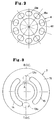
- the cylinder block 4 also has ten connecting ports 13a communicating with the respective hydraulic chambers 13 and opening at the surface 4f of the cylinder block 4, as shown in FIG. 2. the open ends of the connecting ports 13a are angularly spaced along a common circle.
- the distribution valve plate 7 has a single arcuate discharge port (outlet port) 14 defined in one side of the surface 7f and communicating with those connecting ports 13a which confront said one side of the surface 7f, and a single arcuate suction port (inlet port) 15 defined in the other side of the surface 7f and communicating with those connecting ports 13a which confront the other side of the surface 7f.
- the discharge and suction ports 14, 15 communicate respectively with discharge and suction passages 14a, 15a defined in the distribution valve plate 7.
- Shoes 16 are angularly movably coupled to the distal ends of the respective plungers 12, and slidably held against the swash plate 6. To keep the shoes 16 in slidable contact with the swash plate 6, the shoes 16 are pressed against the swash plate 6 by a retainer plate 17 fastened to the swash plate holder 8.
- the cylinder block 4 is also rotated counterclockwise.
- the shoe 16 coupled to the distal end of the plunger 12 which is positioned at its bottom dead center (BDC) in a most expanded state, for example, then slides up the tilted swash plate 6.
- BDC bottom dead center
- the shoe and the plunger 12 coupled thereto are pushed by the swash plate 6 so that the plunger 12 enters the cylinder bore 11 in a discharge stroke.
- the hydraulic chamber 13 defined by the plunger 12 is now compressed, forcing working oil therein to flow under pressure into the discharge port 14 in the distribution valve plate 7.
- TDC top dead center
- the ends of the discharge and suction ports 14, 15 in the distribution valve plate 7 are spaced from each other by distances greater than the diameter of the connecting ports 13a.
- the corresponding connecting port 13a is held in contact with the suction port 15, but spaced from the discharge port 14, as indicated by the two-dot-and-dash line.
- the corresponding connecting port 13a is held in contact with the discharge port 14, but spaced from the suction port 15, as indicated by the two-dot-and-dash line.
- FIGS. 4 and 5 show the relationship between the position of the plunger 12 (i.e., the angular displacement of the cylinder block 4) and the hydraulic pressure in the hydraulic chamber 13 defined by the plunger 12 as shown in FIGS. 4 and 5.
- FIG. 5 shows the cylinder block 4 and the swash plate holder 8 as viewed in the direction indicated by the arrows II in FIG. 1.
- FIGS. 4 and 5 show the manner in which the hydraulic pressure P in the hydraulic chamber 13 defined by a plunger 12 at its BDC when the angular displacement ⁇ of the cylinder block 4 is 0° varies as the angular displacement ⁇ varies.
- An angular interval from the angular displacement 0° to the angular displacement ⁇ 1 is a pressure-increasing (pre-compressing) interval
- an angular interval from the angular displacement 180° to the angular displacement ⁇ 2 is a pressure-reducing (pre-expanding) interval.
- the hydraulic pressure P gradually varies from a lower pressure PL to a higher pressure PH in the pressure-increasing interval
- the hydraulic pressure P gradually varies from the higher pressure PH to the lower pressure PL in the pressure-reducing interval.
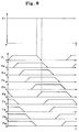
- FIG. 6 shows how thrust loads F1 through F10 acting on the respective ten plungers 12 and a total Ft of these thrust loads vary with time as the cylinder block 4 rotates. It can be seen from FIG. 6 that any variations or fluctuations of the total thrust load Ft can theoretically be eliminated by selecting the angular displacements ⁇ 1, ⁇ 2, ⁇ 3.
- the amount of change in pressure may vary when a tilting angle of the swash plate is changed.
- the angular displacements ⁇ 1, ⁇ 2 and ⁇ 3 are set as described above, the total thrust load Ft is not varied even if the tilting angle is changed.
- the angular displacements ⁇ 1 and ⁇ 2 may be better to be made as small as possible.
- a distribution valve plate 7' may have V-shaped grooves 14a, 15a at ends of discharge and suction ports 14, 15 to achieve the gradual change of the hydraulic pressure as shown in FIGS. 4 and 5.
- V-shaped grooves 14a, 15a may be replaced with holes or valves to obtain the hydraulic pressure change as shown in FIG. 4.
- the hydraulic pressure in the hydraulic chamber 13 starts increasing or decreasing as the connecting port 13a starts moving from positions corresponding to the BDC or the TDC upon rotation of the cylinder block 4.
- the hydraulic pressure in the hydraulic chamber 13 starts increasing or decreasing as the connecting port 13a starts moving from positions different from the BDC or the TDC.
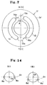
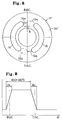
- discharge and suction ports 14, 15 may be defined in a distribution valve plate 7" such that the hydraulic pressure in the hydraulic chamber 13 starts increasing or decreasing as the connecting port 13a starts moving from positions displaced off the BDC or the TDC in a direction shown in FIG. 8.
- the hydraulic pressure P in the hydraulic chamber 13 varies as shown in FIG. 9.
- the position from which the connecting port 13a starts moving in starting to increase or decrease the hydraulic pressure in the hydraulic chamber 13 may be displaced off the BDC or the TDC in a direction opposite to the direction shown in FIG. 8.
- the distance h from the center of the distal end of the plunger 12 about which the shoe 16 is angularly movable to the sliding surface of the swash plate 6, is equal to the distance c from the center 01 of the trunnion 8a to the sliding surface of the swash plate 6.
- the center 01 of the trunnion 8a is aligned with the center 02 of the circular path of the plunger 12 on the sliding surface of the swash plate 6.
- the moment M defined by the equation (1) is based on the pressing force F acting on a single plunger 12.
- the respective moments M acting on all the plungers 12 are added to determine a total moment Mt acting about the trunnion 8a.
- FIG. 12 shows pulsating ratio ⁇ of the total thrust moment Mt at certain angular displacements when the angular displacements ⁇ 1, ⁇ 2 vary from 0° to 90° , with the number Z of plungers 12 being 10, and FIG. 13 shows such pulsating ratios ⁇ with the number Z of plungers 12 being 12.
- a distribution valve plate 7' may have V-shaped grooves 14a, 15a at ends of discharge and suction ports 14, 15 to achieve the gradual change of the hydraulic pressure as shown in FIGS. 15 and 16.
- the swash-plate plunger-type hydraulic pump is of the variable displacement type wherein the swash plate is tiltable through different angles.
- the swash-plate plunger-type hydraulic pump may be of the fixed displacement type.
- a swash-plate plunger-type hydraulic pump or motor only.
- a swas-plate plunger-type hydraulic pump and a swash-plate plunger-type hydraulic motor of the above arrangement may be combined into a hydraulically operated continuously variable transmission.
- FIG. 15 shows such a hydraulically operated continuously variable transmission by way of example.
- the hydraulically operated continuously variable transmission shown in FIG. 15 includes a hydraulic pump P and a hydraulic motor M which are coaxially disposed in a space surrounded by transmission cases 20a, 20b, 20c.
- the hydraulic pump P has an input shaft 21 coupled to the output shaft of an engine.
- the hydraulic pump P comprises a pump cylinder 60 splined to the input shaft 21 and having a plurality of equally angularly spaced cylinder bores 61 arranged along a common circle, and a plurality of pump plungers 62 slidably fitted in the respective cylinder bores 61.
- the pump cylinder 60 is rotatable by the power of the engine transmitted through the input shaft 21.
- the hydraulic motor M comprises a motor cylinder 70 surrounding the pump cylinder 60 and having a plurality of equally angularly spaced cylinder bores 71 arranged along a common circle, and a plurality of motor plungers 72 slidably fitted in the respective cylinder bores 71.
- the motor cylinder 70 is rotatable coaxially with the pump cylinder 60 relatively thereto.
- the motor cylinder 70 comprises first through fourth cylinder segments 70a through 70d which are axially arranged and fastened securely together.
- the first cylinder segment 70a has a lefthand end (as shown) rotatably supported in the case 20a by a bearing 79a and a righthand end inclined to the input shaft 21 and serving as a pump swash plate holder in which a tilted pump swash plate ring 63 is mounted.
- the second cylinder segment 70b has the cylinder bores 71 defined therein.
- the third cylinder segment 70c has a distribution disk 80 having hydraulic passages in communication with the cylinder bores 61, 71.
- the fourth cylinder segment 70d is coupled to the third cylinder segment 70c, and rotatably supported in the case 20b by a bearing 79b.
- An annular pump shoe 64 is slidably mounted on the pump swash plate ring 63, and angularly movably coupled to the pump plunger 62 through connecting rods 65, respectively.
- the pump shoe 64 and the pump cylinder 60 have respective bevel gears 68a, 68b meshing with each other. Therefore, when the pump cylinder 60 is rotated by the input shaft 1, the pump shoe 64 is also rotated in unison therewith. Because the pump swash plate ring 63 is tilted, the pump plungers 62 are reciprocally moved in the cylinder bores 61, drawing working oil from a suction port and discharging working oil into a discharge port.
- a swash plate holder 73 positioned in axially confronting relation to the motor plungers 72 is angularly movably supported in the cases 20a, 20b by a pair of trunnions (support shafts) 73a which project from outer ends of the swash plate holder 73 in directions normal to the sheet of FIG. 13.
- a motor swash plate ring 73b is mounted on the surface of the swash plate holder 73 which faces the motor plungers 72.
- Motor shoes 74 are slidably mounted on the motor swash plate ring 73b, and angularly movably coupled to the respective distal ends of the motor plungers 72.
- the swash plate holder 73 is coupled, at an end remote from the trunnions 73a, to a piston rod 33 of a servo unit 30 through a link 39.
- the piston rod 33 is axially moved to cause the swash plate holder 73 to swing about the trunnions 73a for varying a speed reduction ratio (described later on).
- the fourth cylinder segment 70d is of a hollow structure, and a fixed shaft 91 fixed to a pressure distribution member 18 is disposed centrally in the hollow fourth cylinder segment 70d.
- a distribution ring 100 is fitted over the lefthand end (as shown) of the fixed shaft 91 in a fluid-tight fashion.
- the distribution ring 100 has a lefthand end surface slidably held against the distribution disk 80.
- the distribution ring 100 divides the hollow space in the fourth cylinder segment 70d into a radially inner first hydraulic passage La and a radially outer second hydraulic passage Lb.
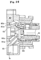
- the distribution disk 80 and the structure within the fourth cylinder segment 70d are shown in detail in FIG. 16.
- the distribution disk 80 has a pump discharge port 81a defined therein, a pump suction port 82a defined therein a pump discharge passage 81b defined therein communicating with the pump discharge port 81a, and a pump suction passage 82b defined therein and communication with the pump suction port 82a.
- the cylinder bores 61 housing those pump plungers 62 that are in a discharge stroke communicate with the radially inner first hydraulic passage La through the pump discharge port 81a and the pump discharge passage 81b.
- the cylinder bores 61 housing those pump plungers 62 that are in a suction stroke communicate with the radially outer second hydraulic passage Lb through the pump suction port 82a and the pump suction passage 82b.
- the distribution disk 80 also has as many connecting passages 83 as the number of the plungers 72, the connecting passages 83 communicating with the respective cylinder bores 71 which house the respective motor plungers 72.
- the connecting passages 83 have open ends that communicate with the first hydraulic passage La or the second hydraulic passage Lb through the distribution ring 100 upon rotation of the motor cylinder 70.
- the cylinder bores 71 housing those motor plungers 72 which are in an expansion stroke are held in communication with the first hydraulic passage La through the connecting passages 83, and the cylinder bores 71 housing those motor plungers 72 which are in a compression stroke are held in communication with the second hydraulic passage Lb through the connecting passages 83.
- the motor cylinder 70 is rotated by the sum of a reactive torque that is applied to the motor cylinder 70 by those pump plungers 62 in the discharge stroke through the pump swash plate ring 63 and a reactive torque that is applied to those motor plungers 72 which are in the expansion stroke by the motor swash plate holder 73.
- the speed reduction ratio i i.e., the ratio of the rotational speed of the motor cylinder 70 to the rotational speed of the pump cylinder 60, is given as follows:
- the speed reduction ratio i can continuously be varied from 1 (minimum value) to a certain ratio (maximum value).
- the speed reduction ratio i is controlled by the servo unit 30 so that an actual engine speed N E coincides with a reference engine speed Neo, the reference engine speed Neo being set based on an accelerator opening.
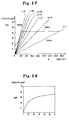
- the rotational speed N p of the pump P (the relative rotational speed of the pump cylinder 60 to the pump swash plate ring 63) continuously varies from 3600 rpm to 0 rpm as shown in FIG. 18, theoretically.
- the pump rotational speed N p varies drastically though the engine speed is being kept constant.
- the amount of fluid sucked and discharged by the pump P greatly varies, and therefore a pressure loss caused during discharging stroke also greatly varies. Therefore the angular displacement ⁇ 1 in which the hydraulic pressure increases and the angular displacement ⁇ 2 in which the hydraulic pressure decreases vary. It is difficult to maintain them constant.
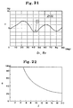
- FIG. 21 shows the fluctuation ratio ⁇ of the total thrust load Ft at some angular displacements when the angular displacements ⁇ 1, ⁇ 2 vary from 0° to 90° .
- Study of FIG. 21 indicates that the ratio ⁇ becomes substantially zero when the angular displacement ⁇ 1 and ⁇ 2 are equal to 40° or 80° .
- the ratio is also varied. Accordingly, if the number of the pump plungers 62 is odd, the fluctuation ratio ⁇ of the total thrust load tends to become large, thereby noise from the transmission being increased.
- the total thrust load Ft does not vary. Accordingly in the transmission according to the present invention, fluctuating forces produced due to the total thrust load Ft can be reduced, thus suppressing noise of the transmission.
- the hydraulic motor M of the above hydraulically operated continuously variable transmission also has an even number (i.e. ten) of motor plungers 72.
- the fluctuating forces produced by the total thrust load Ft is also reduced in the motor M, thus suppressing noise.
- the hydraulic motor is of variable displacement type wherein the swash plate holder 73 is tiltable around the trunion shaft 73a.
- the displacement volume D M of the motor plunger 72 as well as the rotational speed N M of the motor M varies in correspondence with the speed reduction ratio i.
- the angular displacement ⁇ 1 and ⁇ 2 in the motor M is much greater than in the pump P. Accordingly, it is very effective to make the number of the motor plungers 72 even to reduce noise.
- the hydraulically operated continuously variable transmission composed of the hydraulic pump P and the hydraulic motor M is used as the transmission of a motor vehicle, while the motor vehicle is running at high speed, the hydraulic motor M also rotates at high speed.
- the total moment Mt produced by pressing forces from the motor plungers 72 fluctuates, the variation of the total moment Mt is applied as a vibrating force to the swash plate holder 73, causing the transmission to produce high-frequency noise.
- Such high-frequency noise can be prevented from being generated when the ports of the hydraulic motor M are defined to satisfy the equations (2) and (3) above to minimize any fluctuation of the total moment Mt.
- the power transmitting efficiency will be reviewed in greater detail below.
- Hydraulic pressure transmission ratio 1 - (1/i)
- the overall power transmitting efficiency ⁇ of the hydraulically operated continuously variable transmission shown in FIG. 15 is:
- the hydraulically operated continuously variable transmission can be operated with a higher efficiency than the hydraulic pump itself. Stated otherwise, the hydraulic device according to the present invention is highly advantageous from the standpoint of efficiency if incorporated in hydraulically operated continuously variable transmissions.
- a second embodiment of the present invention will be described below.
- the second embodiment is also embodied in the hydraulic pump shown in FIG. 1.
- the ends of the discharge and suction ports 14, 15 in the distribution valve plate 7 are spaced from each other by distances greater than the diameter of the connecting ports 13a.
- the corresponding connecting port 13a is held in contact with the suction port 15, but spaced from the discharge port 14, as indicated by the two-dot-and-dash line.
- the corresponding connecting port 13a is held in contact with the discharge port 14, but spaced from the suction port 15, as indicated by the two-dot-and-dash line.
- FIGS. 4 and 5 show the manner in which the hydraulic pressure P in the hydraulic chamber 13 defined by a plunger 12 at its BDC when the angular displacement ⁇ of the cylinder block 4 is 0° varies as the angular displacement ⁇ varies.
- An angular interval from the angular displacement 0° to the angular displacement ⁇ 1 is a pressure-increasing (pre-compressing) interval
- an angular interval from the angular displacement 180° to the angular displacement ⁇ 2 is a pressure-reducing (pre-expanding) interval.
- the hydraulic pressure P gradually varies from a lower pressure PL to a higher pressure PH in the pressure-increasing interval
- the hydraulic pressure P gradually varies from the higher pressure PH to the lower pressure PL in the pressure-reducing interval.
- the discharge and suction ports 14, 15 are defined such that the angular displacements ⁇ 1, ⁇ 2 are equal to each other, and the angular displacement ⁇ 3 is 180° .
- FIG. 21 shows the relationship between the pulsating ratio ⁇ of a discharged flow and the angular displacements ⁇ 1, ⁇ 2 in the hydraulic pump where the angular displacements ⁇ 1, ⁇ 2, ⁇ 3 are selected as described above and ten plungers 12 are employed.
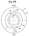
- the value ⁇ of the angular displacements ⁇ 1, ⁇ 2 which makes the pulsating ratio ⁇ minimum varies depending on the number Z of plungers used.
- the relationship between the value ⁇ and the number Z is shown in FIG. 22.
- angular displacements ⁇ 1, ⁇ 2, ⁇ 3 should be selected as described above. It may be difficult to cause the hydraulic pressure to vary gradually in the pressure-increasing interval of the angular displacement ⁇ 1 and the pressure-reducing interval of the angular displacement ⁇ 2 as shown in FIGS. 4 and 5. To eliminate such difficulty, as shown in FIG. 23, a distribution valve plate 7' may have V-shaped grooves 14a, 15a at ends of discharge and suction ports 14, 15 to achieve the gradual change of the hydraulic pressure as shown in FIGS. 23 and 24.
- V-shaped grooves 14a, 15a may be replaced with holes or valves to obtain the hydraulic pressure change as shown in FIG. 4.
- the swash-plate plunger-type hydraulic pump is of the variable displacement type wherein the swash plate is tiltable through different angles.
- the swash-plate plunger-type hydraulic pump may be of the fixed displacement type.
- the hydraulically operated continuously variable transmission composed of the hydraulic pump P and the hydraulic motor M is used as the transmission of a motor vehicle, while the motor vehicle is running at high speed, the hydraulic motor M also rotates at high speed.
- the transmission may produce high-frequency noise due to an abrupt change in the hydraulic pressure in the cylinder bores of the motor and a large pulsation of the discharged flow.
- Such high-frequency noise can be prevented from being generated when an even number of motor plungers 72 are employed, the angular displacements ⁇ 1, ⁇ 2 are substantially equal to the angle according to the equation (4) above, and the angular displacement ⁇ 3 is 180° .
- the power transmitting efficiency will be reviewed in greater detail below.
- the overall power transmitting efficiency ⁇ of the hydraulic pump itself as shown in FIG. 1 is 90 %.
- the overall power transmitting efficiency ⁇ of the hydraulically operated continuously variable transmission shown in FIG. 15 is:
- the hydraulically operated continuously variable transmission can be operated with a higher efficiency than the hydraulic pump itself. Stated otherwise, the hydraulic device according to the present invention is highly advantageous from the standpoint of efficiency if incorporated in hydraulically operated continuously variable transmissions.
- a swash-plate plunger-type hydraulic device has a cylinder block with a plurality of plungers slidably fitted in cylinder bores, a swash plate confronting one end of the cylinder block, and a distribution valve plate slidably held against the other end of the cylinder block.
- the cylinder block has an even number of circularly arrayed connecting ports communicating with the cylinder bores and opening at the other end thereof.
- the distribution valve plate has inlet and outlet ports.
- the cylinder block is rotatable through an angular displacement ⁇ 1 in which the hydraulic pressure in one connecting port between the inlet and outlet ports increases from a lower pressure to a higher pressure, through an angular displacement ⁇ 2 in which the hydraulic pressure in one connecting port between the inlet and output ports decreases from the higher pressure to the lower pressure, and through an angular displacement ⁇ 3 from a position where the hydraulic pressure starts to increase to a position where the hydraulic pressure starts to decrease.
Landscapes
- Engineering & Computer Science (AREA)
- Mechanical Engineering (AREA)
- General Engineering & Computer Science (AREA)
- Reciprocating Pumps (AREA)
Applications Claiming Priority (4)
| Application Number | Priority Date | Filing Date | Title |
|---|---|---|---|
| JP42547/91 | 1991-02-14 | ||
| JP3042548A JP2974164B2 (ja) | 1991-02-14 | 1991-02-14 | 斜板プランジャ式油圧装置 |
| JP42548/91 | 1991-02-14 | ||
| JP3042547A JP2974163B2 (ja) | 1991-02-14 | 1991-02-14 | 斜板プランジャ式油圧装置 |
Publications (3)
| Publication Number | Publication Date |
|---|---|
| EP0499961A2 true EP0499961A2 (de) | 1992-08-26 |
| EP0499961A3 EP0499961A3 (en) | 1993-03-10 |
| EP0499961B1 EP0499961B1 (de) | 1995-05-03 |
Family
ID=26382257
Family Applications (1)
| Application Number | Title | Priority Date | Filing Date |
|---|---|---|---|
| EP92102343A Expired - Lifetime EP0499961B1 (de) | 1991-02-14 | 1992-02-12 | Taumelscheiben-Kolbenhydraulikanlage |
Country Status (3)
| Country | Link |
|---|---|
| US (1) | US5317873A (de) |
| EP (1) | EP0499961B1 (de) |
| DE (1) | DE69202269T2 (de) |
Cited By (5)
| Publication number | Priority date | Publication date | Assignee | Title |
|---|---|---|---|---|
| CN107110134A (zh) * | 2014-11-18 | 2017-08-29 | 罗伯特·博世有限公司 | 轴向柱塞机 |
| CN110067715A (zh) * | 2019-03-13 | 2019-07-30 | 钟彪 | 一种配流滑盘副及包含该结构的柱塞泵或马达 |
| CN110573750A (zh) * | 2017-04-28 | 2019-12-13 | Smc 株式会社 | 增压装置以及具备该增压装置的气缸装置 |
| CN113858258A (zh) * | 2021-10-08 | 2021-12-31 | 武汉科技大学 | 一种轴向配油的连续旋转液压关节 |
| EP4459123A1 (de) * | 2023-05-03 | 2024-11-06 | Innas B.V. | Hydraulische vorrichtung |
Families Citing this family (18)
| Publication number | Priority date | Publication date | Assignee | Title |
|---|---|---|---|---|
| JP3345227B2 (ja) * | 1995-08-25 | 2002-11-18 | ブラザー工業株式会社 | ポンプ |
| US5601417A (en) * | 1995-11-21 | 1997-02-11 | Ball Bearing Pump, Inc. | Hydraulic pump with ball bearing pistons |
| US20050039555A1 (en) * | 2001-05-01 | 2005-02-24 | Kerian Thomas S. | Precession modulated continuously variable transmission |
| US7086225B2 (en) * | 2004-02-11 | 2006-08-08 | Haldex Hydraulics Corporation | Control valve supply for rotary hydraulic machine |
| FR2872880B1 (fr) * | 2004-07-12 | 2007-11-02 | Hydro Leduc Soc Par Actions Si | Dispositif hydraulique d'entrainement d'un recepteur tournant |
| US20070009367A1 (en) * | 2005-04-21 | 2007-01-11 | Kmt Waterjet Systems, Inc. | Close fit cylinder and plunger |
| DE102005027764B4 (de) * | 2005-06-15 | 2010-01-07 | Eurocopter Deutschland Gmbh | Vibrationsgenerierungsvorrichtung |
| ITRE20050110A1 (it) * | 2005-10-04 | 2007-04-05 | Orles Ferretti | Sistema di distribuzione per unita' idrostatica a pistoni |
| US20080226471A1 (en) * | 2007-03-12 | 2008-09-18 | Kabushiki Kaisha Toyota Jidoshokki | Variable displacement compressor |
| KR101187598B1 (ko) * | 2010-07-20 | 2012-10-04 | 한국과학기술연구원 | 유압발생장치 |
| CN102788010B (zh) * | 2012-08-10 | 2015-11-18 | 中国船舶重工集团公司第七一九研究所 | 一种摆动油缸控制的斜盘柱塞式液压变压器 |
| FR3005607B1 (fr) * | 2013-05-16 | 2016-11-18 | Technoboost | Transmission pour vehicule hybride hydraulique, comportant un train planetaire relie a une pompe par un reducteur de vitesse |
| US9003955B1 (en) | 2014-01-24 | 2015-04-14 | Omax Corporation | Pump systems and associated methods for use with waterjet systems and other high pressure fluid systems |
| CN105485068B (zh) * | 2016-01-28 | 2017-06-06 | 吉林大学 | 双斜盘串联式液压变压器 |
| US10808688B1 (en) | 2017-07-03 | 2020-10-20 | Omax Corporation | High pressure pumps having a check valve keeper and associated systems and methods |
| EP4127527A1 (de) | 2020-03-24 | 2023-02-08 | Hypertherm, Inc. | Hochdruckdichtung für ein flüssigkeitsstrahlschneidsystem |
| KR102993730B1 (ko) | 2020-03-30 | 2026-07-21 | 하이퍼썸, 인크. | 다기능 접속 종방향 단부들을 갖는 액체 제트 펌프를 위한 실린더 |
| CN112796968A (zh) * | 2020-12-03 | 2021-05-14 | 北京航空航天大学宁波创新研究院 | 一种斜盘内嵌式回程结构及具有该结构的柱塞泵 |
Family Cites Families (12)
| Publication number | Priority date | Publication date | Assignee | Title |
|---|---|---|---|---|
| US2299235A (en) * | 1937-06-09 | 1942-10-20 | Ex Cell O Corp | Hydraulic pump |
| DE900530C (de) * | 1951-06-30 | 1953-12-28 | Heinrich Ebert Dr Ing | Steuerspiegel fuer die Kolbentrommel hydraulischer Axialkolbenmaschinen mit ungerader Kolbenanzahl |
| US2853025A (en) * | 1953-04-27 | 1958-09-23 | Vickers Inc | Power transmission |
| US3036434A (en) * | 1960-12-29 | 1962-05-29 | Massey Ferguson Inc | Thrust bearings for hydrostatic transmissions |
| DE1703347A1 (de) * | 1968-05-06 | 1972-01-13 | Mannesmann Meer Ag | Hydrostatische Axialkolbenmaschine |
| FR2082604A5 (de) * | 1970-03-20 | 1971-12-10 | Boyer Jean | |
| DE2208890A1 (de) * | 1972-02-25 | 1973-09-06 | Bosch Gmbh Robert | Axialkolbenpumpe |
| JPS61118566A (ja) * | 1984-11-14 | 1986-06-05 | Honda Motor Co Ltd | 斜板型油圧装置 |
| US4749542A (en) * | 1986-10-07 | 1988-06-07 | The United States Of America As Represented By The United States Department Of Energy | Removable check valve for use in a nuclear reactor |
| JPH0660673B2 (ja) * | 1986-12-12 | 1994-08-10 | 本田技研工業株式会社 | 油圧式無段変速機 |
| US5033358A (en) * | 1988-01-04 | 1991-07-23 | Hans Molly | Axial piston type motor |
| JPH02129461A (ja) * | 1988-11-09 | 1990-05-17 | Honda Motor Co Ltd | 油圧式無段変速機 |
-
1992
- 1992-02-12 DE DE69202269T patent/DE69202269T2/de not_active Expired - Fee Related
- 1992-02-12 EP EP92102343A patent/EP0499961B1/de not_active Expired - Lifetime
- 1992-02-13 US US07/836,622 patent/US5317873A/en not_active Expired - Fee Related
Cited By (7)
| Publication number | Priority date | Publication date | Assignee | Title |
|---|---|---|---|---|
| CN107110134A (zh) * | 2014-11-18 | 2017-08-29 | 罗伯特·博世有限公司 | 轴向柱塞机 |
| CN107110134B (zh) * | 2014-11-18 | 2019-06-18 | 罗伯特·博世有限公司 | 轴向柱塞机 |
| CN110573750A (zh) * | 2017-04-28 | 2019-12-13 | Smc 株式会社 | 增压装置以及具备该增压装置的气缸装置 |
| CN110067715A (zh) * | 2019-03-13 | 2019-07-30 | 钟彪 | 一种配流滑盘副及包含该结构的柱塞泵或马达 |
| CN110067715B (zh) * | 2019-03-13 | 2024-06-07 | 上海强田驱动技术有限公司 | 一种配流滑盘副及包含该结构的柱塞泵或马达 |
| CN113858258A (zh) * | 2021-10-08 | 2021-12-31 | 武汉科技大学 | 一种轴向配油的连续旋转液压关节 |
| EP4459123A1 (de) * | 2023-05-03 | 2024-11-06 | Innas B.V. | Hydraulische vorrichtung |
Also Published As
| Publication number | Publication date |
|---|---|
| EP0499961B1 (de) | 1995-05-03 |
| US5317873A (en) | 1994-06-07 |
| EP0499961A3 (en) | 1993-03-10 |
| DE69202269D1 (de) | 1995-06-08 |
| DE69202269T2 (de) | 1995-09-07 |
Similar Documents
| Publication | Publication Date | Title |
|---|---|---|
| EP0499961B1 (de) | Taumelscheiben-Kolbenhydraulikanlage | |
| JP3429764B2 (ja) | 連接棒のないピストンを備える流体作動機械 | |
| US7677871B2 (en) | High-efficiency, large angle, variable displacement hydraulic pump/motor | |
| EP0918176B1 (de) | Hydrostatisches, stufenloses Getriebe | |
| US3199460A (en) | Hydraulic pump or motor | |
| EP0736152B1 (de) | Stufenlos verstellbares, hydrostatisches getriebe | |
| US4967556A (en) | Hydrostatically operated continuously variable transmission | |
| JPH03115782A (ja) | ラジアルピストン装置 | |
| Mommers et al. | ‘Shuttle’technology for noise reduction and efficiency improvement of hydrostatic machines-Part 2 | |
| EP0499951B1 (de) | Taumelscheiben-Kolbenhydraulikanlage | |
| US4747266A (en) | Hydromotor | |
| JPH01267367A (ja) | 多連ピストンポンプ | |
| US3211105A (en) | Hydraulic pump or motor | |
| US4972675A (en) | Hydraulically operated continuously variable transmission | |
| US5535589A (en) | Ratio controller for continuously variable hydrostatic transmission | |
| JP2920772B2 (ja) | 静油圧式無段変速機 | |
| US20090120278A1 (en) | Electrohydrostatic actuator including a four-port, dual displacement hydraulic pump | |
| US3179060A (en) | Silent variable delivery hydraulic pump | |
| JP2960456B2 (ja) | アキシアルピストン機械 | |
| US2853025A (en) | Power transmission | |
| USRE26519E (en) | Variable displacement pump | |
| US5551844A (en) | Reciprocating compressor with double headed pistons | |
| JP3514356B2 (ja) | 多段式圧縮機 | |
| JP2974164B2 (ja) | 斜板プランジャ式油圧装置 | |
| JP2974166B2 (ja) | 斜板プランジャ式油圧装置 |
Legal Events
| Date | Code | Title | Description |
|---|---|---|---|
| PUAI | Public reference made under article 153(3) epc to a published international application that has entered the european phase |
Free format text: ORIGINAL CODE: 0009012 |
|
| AK | Designated contracting states |
Kind code of ref document: A2 Designated state(s): DE FR GB IT |
|
| PUAL | Search report despatched |
Free format text: ORIGINAL CODE: 0009013 |
|
| AK | Designated contracting states |
Kind code of ref document: A3 Designated state(s): DE FR GB IT |
|
| 17P | Request for examination filed |
Effective date: 19930420 |
|
| 17Q | First examination report despatched |
Effective date: 19940919 |
|
| GRAA | (expected) grant |
Free format text: ORIGINAL CODE: 0009210 |
|
| AK | Designated contracting states |
Kind code of ref document: B1 Designated state(s): DE FR GB IT |
|
| ITF | It: translation for a ep patent filed | ||
| REF | Corresponds to: |
Ref document number: 69202269 Country of ref document: DE Date of ref document: 19950608 |
|
| ET | Fr: translation filed | ||
| PLBE | No opposition filed within time limit |
Free format text: ORIGINAL CODE: 0009261 |
|
| STAA | Information on the status of an ep patent application or granted ep patent |
Free format text: STATUS: NO OPPOSITION FILED WITHIN TIME LIMIT |
|
| 26N | No opposition filed | ||
| PGFP | Annual fee paid to national office [announced via postgrant information from national office to epo] |
Ref country code: GB Payment date: 19990204 Year of fee payment: 8 |
|
| PGFP | Annual fee paid to national office [announced via postgrant information from national office to epo] |
Ref country code: FR Payment date: 19990226 Year of fee payment: 8 |
|
| PG25 | Lapsed in a contracting state [announced via postgrant information from national office to epo] |
Ref country code: GB Free format text: LAPSE BECAUSE OF NON-PAYMENT OF DUE FEES Effective date: 20000212 |
|
| GBPC | Gb: european patent ceased through non-payment of renewal fee |
Effective date: 20000212 |
|
| PG25 | Lapsed in a contracting state [announced via postgrant information from national office to epo] |
Ref country code: FR Free format text: LAPSE BECAUSE OF NON-PAYMENT OF DUE FEES Effective date: 20001031 |
|
| REG | Reference to a national code |
Ref country code: FR Ref legal event code: ST |
|
| PGFP | Annual fee paid to national office [announced via postgrant information from national office to epo] |
Ref country code: DE Payment date: 20010205 Year of fee payment: 10 |
|
| PG25 | Lapsed in a contracting state [announced via postgrant information from national office to epo] |
Ref country code: DE Free format text: LAPSE BECAUSE OF NON-PAYMENT OF DUE FEES Effective date: 20020903 |
|
| PG25 | Lapsed in a contracting state [announced via postgrant information from national office to epo] |
Ref country code: IT Free format text: LAPSE BECAUSE OF NON-PAYMENT OF DUE FEES Effective date: 20050212 |