EP0500963B1 - Dreiphasen-reluktanz-motor - Google Patents
Dreiphasen-reluktanz-motor Download PDFInfo
- Publication number
- EP0500963B1 EP0500963B1 EP91915991A EP91915991A EP0500963B1 EP 0500963 B1 EP0500963 B1 EP 0500963B1 EP 91915991 A EP91915991 A EP 91915991A EP 91915991 A EP91915991 A EP 91915991A EP 0500963 B1 EP0500963 B1 EP 0500963B1
- Authority
- EP
- European Patent Office
- Prior art keywords
- magnetic poles
- magnetic
- phase
- accordance
- exciting coils
- Prior art date
- Legal status (The legal status is an assumption and is not a legal conclusion. Google has not performed a legal analysis and makes no representation as to the accuracy of the status listed.)
- Expired - Lifetime
Links
- 230000002093 peripheral effect Effects 0.000 claims description 10
- 230000009467 reduction Effects 0.000 claims description 9
- 230000004044 response Effects 0.000 claims description 4
- 238000000638 solvent extraction Methods 0.000 claims description 3
- 230000003213 activating effect Effects 0.000 claims description 2
- 230000007423 decrease Effects 0.000 abstract description 5
- 239000003990 capacitor Substances 0.000 description 18
- 230000004907 flux Effects 0.000 description 5
- 230000008033 biological extinction Effects 0.000 description 4
- RYGMFSIKBFXOCR-UHFFFAOYSA-N Copper Chemical compound [Cu] RYGMFSIKBFXOCR-UHFFFAOYSA-N 0.000 description 3
- 238000009825 accumulation Methods 0.000 description 3
- 238000010586 diagram Methods 0.000 description 3
- 229920006395 saturated elastomer Polymers 0.000 description 3
- 230000007704 transition Effects 0.000 description 3
- XEEYBQQBJWHFJM-UHFFFAOYSA-N Iron Chemical compound [Fe] XEEYBQQBJWHFJM-UHFFFAOYSA-N 0.000 description 2
- XAGFODPZIPBFFR-UHFFFAOYSA-N aluminium Chemical compound [Al] XAGFODPZIPBFFR-UHFFFAOYSA-N 0.000 description 2
- 229910052782 aluminium Inorganic materials 0.000 description 2
- 230000008859 change Effects 0.000 description 2
- 238000001816 cooling Methods 0.000 description 2
- 229910052802 copper Inorganic materials 0.000 description 2
- 239000010949 copper Substances 0.000 description 2
- 230000000977 initiatory effect Effects 0.000 description 2
- 238000009434 installation Methods 0.000 description 2
- 229910000976 Electrical steel Inorganic materials 0.000 description 1
- 238000010276 construction Methods 0.000 description 1
- 230000003111 delayed effect Effects 0.000 description 1
- 238000009499 grossing Methods 0.000 description 1
- 229910052742 iron Inorganic materials 0.000 description 1
- 238000003475 lamination Methods 0.000 description 1
- 239000000463 material Substances 0.000 description 1
- 230000010355 oscillation Effects 0.000 description 1
- 230000000149 penetrating effect Effects 0.000 description 1
- 238000013341 scale-up Methods 0.000 description 1
Images


Classifications
-
- H—ELECTRICITY
- H02—GENERATION; CONVERSION OR DISTRIBUTION OF ELECTRIC POWER
- H02K—DYNAMO-ELECTRIC MACHINES
- H02K19/00—Synchronous motors or generators
- H02K19/02—Synchronous motors
- H02K19/10—Synchronous motors for multi-phase current
- H02K19/103—Motors having windings on the stator and a variable reluctance soft-iron rotor without windings
-
- H—ELECTRICITY
- H02—GENERATION; CONVERSION OR DISTRIBUTION OF ELECTRIC POWER
- H02K—DYNAMO-ELECTRIC MACHINES
- H02K29/00—Motors or generators having non-mechanical commutating devices, e.g. discharge tubes or semiconductor devices
- H02K29/06—Motors or generators having non-mechanical commutating devices, e.g. discharge tubes or semiconductor devices with position sensing devices
- H02K29/12—Motors or generators having non-mechanical commutating devices, e.g. discharge tubes or semiconductor devices with position sensing devices using detecting coils using the machine windings as detecting coil
-
- H—ELECTRICITY
- H02—GENERATION; CONVERSION OR DISTRIBUTION OF ELECTRIC POWER
- H02P—CONTROL OR REGULATION OF ELECTRIC MOTORS, ELECTRIC GENERATORS OR DYNAMO-ELECTRIC CONVERTERS; CONTROLLING TRANSFORMERS, REACTORS OR CHOKE COILS
- H02P25/00—Arrangements or methods for the control of AC motors characterised by the kind of AC motor or by structural details
- H02P25/02—Arrangements or methods for the control of AC motors characterised by the kind of AC motor or by structural details characterised by the kind of motor
- H02P25/08—Reluctance motors
- H02P25/086—Commutation
- H02P25/089—Sensorless control
Definitions
- the present invention relates to a reluctance type motor, particularly to a three-phase reluctance type motor capable of outputting large torque and preferable for using as a driving source for various industrial apparatus.
- a typical three-phase reluctance type motor comprises a stator having six magnetic poles and a rotor having four or eight salient-poles.
- Three sets of magnetic poles are associated with three sets of exciting coils constituting a first to a third phase exciting coils, respectively.
- exciting current is successively supplied to the first to the third exciting coils, the magnetic poles are excited to cause magnetic attraction force between the excited magnetic poles and their corresponding salient-poles. And, this magnetic attraction force causes the rotor to rotate.
- an output torque of the motor increases in accordance with increase of a magnetomotive force (i.e. an ampere-turn) defined by a number of turns of an exciting coil multiplied by its exciting current.
- a magnetomotive force i.e. an ampere-turn
- an output torque increases in proportion to a square value of an exciting current in a region 3a in which the exciting current is smaller than, for example, 2 ampere, and to the contrary it increases in proportion to the exciting current itself in a region 3b in which the exciting current is larger than 2 ampere.
- the output torque of motor can be increased by increasing magnetomotive force of exciting coils.
- an available space inside of the motor which the exciting coils can occupy is limited, therefore it is difficult to scale up the exciting coil in order to increase number of turns of the exciting coil.
- an increase of the exciting current is accompanied with increase of copper loss.
- an initiation and a termination of exciting current supply coincides with a 180-degree electric angle rotation of a rotor. That is, during one complete revolution of the rotor, an accumulation and an extinction of magnetic flux are repeated 6 times. Such a large number of repetition of the accumulation and the extinction of magnetic flux during one complete revolution of the rotor increases iron loss in the reluctance type motor. Moreover, since an inductance of the exciting coil is large, magnetic energy stored in the exciting coil becomes remarkably large. Therefore, it requires significant time for completion of accumulation and extinction of magnetic energy. For this reason, a building-up and a trailing edge of the exciting current are delayed undesirably.
- the purpose of the present invention is to provide a three-phase reluctance type motor of large output torque which can be used as a driving source for various industrial apparatus.
- a three-phase reluctance type motor of the present invention comprises: a fixed armature with three sets of magnetic poles relating to first, second, and third phases which are formed on its inner peripheral surface according to a predetermined order; three sets of exciting coils being associated with the three sets of magnetic poles and relating to the first, the second, and the third phases; and a rotor which is rotatably disposed and has an outer peripheral surface formed with a predetermined number of salient-poles disposed at regular intervals, said predetermined number exceeding a total number of magnetic poles of the fixed armature.
- Each set of magnetic poles consists of adjacent two magnetic poles of opposite polarity and other adjacent two magnetic poles of opposite polarity facing to said adjacent two magnetic poles in a diameter direction of the motor. And, each set of exciting coils are connected with each other.
- a three-phase reluctance type motor in accordance with the present invention comprises: a position detecting device for successively generating a series of position detecting signals in accordance with rotation of the rotor; a current supply control circuit being connected to a direct-current power source for successively activating the three sets of exciting coils in response to the position detecting signals; and a circuit means which discharges magnetic energy stored in one set of exciting coils having been just deactivated into another set of exciting coils to be subsequently activated so that not only the stored magnetic energy can be promptly extinguished but an exciting current flowing into said another set of exciting coils can be steeply increased.
- four magnetic poles consisting of adjacent two magnetic poles and other adjacent two magnetic poles facing to the above adjacent two magnetic poles in a diameter direction of the motor are provided in conjunction with each of the first, the second, and the third phases.
- These four magnetic poles may be excited by four exciting coils associated with these magnetic poles respectively.
- an overall magnetomotive force of exciting coils of respective phases may be largely increased compared with a conventional reluctance type motor which is provided with two exciting coils relating to each of a first, a second, and a third phases.
- a limited installation space for exciting coils inside of the motor is effectively utilized. Accordingly, a magnetomotive force of exciting coils can be increased without scaling up the motor, and therefore the output torque of the motor can be increased.
- magnetic energy stored in one set of exciting coils having been just deactivated is discharged into another set of exciting coils to be subsequently activated, therefore not only the stored magnetic energy can be promptly extinguished but the exciting current flowing said another set of exciting coils can be steeply increased.
- a motor in accordance with the present invention can be driven at a higher rotational speed which is required as a driving source for various industrial apparatus, irrespective of increased number of magnetic poles and salient-poles compared with conventional motors.
- the present invention provides a three-phase reluctance type motor of large output torque capable of being used as a driving source suitable for various industrial apparatus.
- a three-phase half-wave reluctance type motor in accordance with a first embodiment of the present invention comprises a motor main body shown in Fig. 2.
- the motor main body comprises a surrounding wall 23 of a housing, a rotor shaft 5 with its end portions being rotatably supported on bearings (not shown) provided on both end walls of the housing which are respectively fixed to the surrounding wall 23 of the housing, a rotor 1 coupled with the rotor shaft 5, and an armature (i.e. a stator) 16 disposed coaxially with the rotor 1 and fixed on the surrounding wall 23 of the casing.
- the rotor 1 and the armature 16 are respectively made of well-known lamination layer of silicon steel sheet.
- the housing surrounding wall 23 is buried and fixed in an outer peripheral surface of the armature formed with recessed portions 24a to 24f by an aluminum die-cast.
- a die-cast material constituting the surrounding wall 23 intrudes in an outer peripheral portion of the armature 16 by a depth indicated by a letter E in the drawing.
- Connecting portions 21a′ to 24f′ between the surrounding wall 23 and the armature 16 are removed by being cut after having finished the die-cast work. That is, on the armature 16, there are formed with cutouts 24a′ to 21f′ partitioning a magnetic path relating to one adjacent pair of magnetic poles from a magnetic path relating to other adjacent pair of magnetic poles.
- the armature 16 has a circular magnetic core 16′ freely forming a magnetic path, and twelve magnetic poles 16a to 16f and 16a′ to 16f′ are formed at regular intervals in a circumferential direction on an inner peripheral surface of the magnetic core so as to respectively protrude in a radially inward direction. Tip (i.e. distal) ends of the magnetic pole and its opposing salient-pole are disposed to face with each other over an air gap of an approximately 0.15 mm.
- the magnetic poles have respectively the same circumferential width, which is the same width as that of the salient-pole.
- a spaced gap of adjacent two magnetic poles coincides with a section wherein three salient-poles, for example, salient-poles 1a to 1c are disposed. That is, adjacent two magnetic poles are spaced with each other by a distance equal to four times of a width of salient-pole.
- the adjacent two magnetic poles 16a, 16a′ constitute a first set of magnetic poles together with adjacent two magnetic poles 16d, 16d′ which are disposed to oppose above adjacent two magnetic poles 16a, 16a′ in a diameter direction of the motor.
- the first set of magnetic poles relates to a first phase.
- the adjacent two magnetic poles 16b, 16b′ constitute a second set of magnetic poles together with adjacent two magnetic poles 16e, 16e′ which are disposed to oppose above adjacent two magnetic poles 16b, 16b′ in a diameter direction of the motor.
- the second set of magnetic poles relates to a second phase.
- the adjacent two magnetic poles 16c, 16c′ constitute a third set of magnetic poles together with adjacent two magnetic poles 16f, 16f′ which are disposed to oppose above adjacent two magnetic poles 16c, 16c′ in a diameter direction of the motor.
- the third set of magnetic poles relates to a third phase.
- These magnetic poles 16a to 16f and 16a′ to 16f′ are associated with exciting coils 17a to 17f and 17a′ to 17f′, respectively. Since adjacent two magnetic poles are spaced with each other by a distance equal to four times of a width of salient-pole, there is provided a fairly large occupying space for the exciting coils to be coupled with the magnetic poles. Accordingly, it becomes possible to constitute each exciting coil by turning a large diameter copper wire by a required turn number so as to obtain a required magnetomotive force.
- the first set of exciting coils 17a, 17a′, 17d, and 17d′ relating to the first phase are connected with each other in series or in parallel. Otherwise, the first set of exciting coils 17a, 17a′, 17d, and 17d′ are connected in such a manner that two pair of series exciting coils are connected in parallel.
- this connected unit is referred to as a first phase exciting coil K.
- the second set of exciting coils 17b, 17b′, 17e, and 17e′ and the third set of exciting coils 17c, 17c′, 17f, and 17f′ are connected in the same fashion as the first set of exciting coils 17a, 17a′, 17d, and 17d′.
- These connected unit are referred to as a second phase exciting coil L and a third phase exciting coil M.
- the motor comprises a position detecting device shown in Fig. 4.
- the position detecting device includes three detecting elements 10a to 10c (Fig. 3) each consisting of an air-core coil of approximately 100 turns having 5mm diameter for detecting rotational positions of salient-poles 1a to 1z of the rotor 1. These detecting elements (hereinafter, referred to as detecting coils) are respectively spaced by 120 degrees with each other, and respective coil surface are fixed on the armature 16 so as to face to the side surfaces of the salient-poles 1a to 1z with keeping air gaps. Furthermore, the position detecting device includes an oscillator 7 having an oscillation frequency of approximately 1 MHz. An output of the oscillator 7 is connected to a bridge circuit consisting of detecting coils 10a to 10c and resistances 15a to 15e.
- This bridge circuit is adjusted to balance in a condition that the detecting coils 10a to 10c do not face to any of the salient-poles 1a to 1z.
- This bridge circuit is connected to a logic circuit 8 through low-pass filters consisting of diodes 11a to 11d and capacitors 12a to 12d and operational amplifiers 13a to 13c.
- the diodes 11a has an anode connected to the connecting point of the coil 10a and the resistance 15a, and has a cathode connected to both the other end of the capacitor 12a with one end being grounded and the positive input terminal of the operational amplifier 13a.
- the diode 11b has an anode connected to the connecting point of the coil 10b and the resistance 15b and has a cathode connected to both the other end of the capacitor 12b with one end being grounded and the positive input terminal of the operational amplifier 13b.
- the diode 11c has an anode connected to the connecting point of the coil 10c and the resistance 15c and has a cathode connected to both the other end of the capacitor 12c with one end being grounded and the positive input terminal of the operational amplifier 13c.
- the diode 11d has an anode connected to the connecting point of resistances 15d, 15e and has a cathode connected to both the other end of the capacitor 12d with one end being grounded and negative input terminals of the operational amplifiers 13a to 13c. Output terminals of the operational amplifiers 13a to 13c are connected to input terminals of the logic circuit 8.
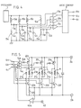
- the motor further comprises a current supply control circuit shown in Fig. 5 to allow or prevent the exciting current supply to the exciting coils 17a to 17f and 17a′ to 17f′; i.e. the first to third phase exciting coils K to M.
- Input terminals 4a to 4c of the current supply control circuit are connected, on one hand, to output terminals 6a to 6c of the position detecting device, and connected, on the other hand, to one side input terminals of AND circuits 14a to 14c of the current supply control circuit, respectively.
- the other side input terminals of the AND circuits 14a to 14c are connected to a standard voltage input terminal 40 to which a standard voltage is applied in order to vary an output torque of the motor, through an operational amplifier 40a constituting a later-described chopper circuit together with the AND circuits.
- output terminals of the AND circuits 14a to 14c are connected through inversion circuits to bases of transistors (i.e. switching elements) 20a, 20c, and 20e interposed between a positive terminal 2a of the DC power source and one ends of the first to the third phase exciting coils K to M.
- the other ends of the first to the third phase exciting coils K to M are connected through transistors 20b, 20d, 20f and resistance 22 to a negative terminal 2b of the DC power source, and on the other hand, connected through transistors 20b, 20d, and 20f to a negative terminal of the operational amplifier 40a.
- the resistance 22 is provided to detect an exciting current flowing the first to the third phase exciting coils K to M.
- One end of the resistance 22 is connected to emitters of the transistors 20b, 20d, and 20f, and the other end is connected to anodes of diodes 21a, 21c, and 21f.
- Cathodes of these diodes 21a, 21c, and 21f are connected to one side ends of the first to the third phase exciting coils K to M.
- diodes 21b, 21d, and 21f are interposed between the other side ends of the first to the third phase exciting coils K to M and the positive terminal 2a of the DC power source.
- the bridge circuit of the position detecting device (Fig. 4) installed in the motor is adjusted to balance when the detecting coils 10a to 10c do not face to any one of the salient-poles 1a to 1z of the rotor 1. Accordingly, when the detecting coil 10a does not face to any one of the salient-poles 1a to 1z, an output of the low-pass filter consisting of the diode 11a and the capacitor 12a becomes equal to an output of the low-pass filter consisting of the diode 11d and the capacitor 12d. Therefore, an output of the operational amplifier 13a becomes a LOW-level. However, as a matter of fact, when the motor is stopped, any one of the detecting coils faces to any one of salient-poles.
- the detecting coil 10a faces to any one of salient-poles
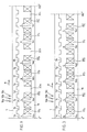
- impedance of the detecting coil 10a decreases due to core loss (i.e. eddy loss and hysteresis loss). Therefore, voltage drop in the resistance 15a becomes large, and an applied voltage to the positive input terminal of the operational amplifier 13a increases to turn the output 25 of the operational amplifier into a HIGH-level (as indicated by the reference numerals 25a, 25b in Fig. 7). That is, in accordance with rotation of the rotor 1, rectangular-wave signals 25 are sent out from the operational amplifier 13a.
- the logic circuit 8 has input terminals inputting these rectangular-wave signals 25 to 27 and outputs rectangular-wave signals 28 to 30 (Fig. 7) corresponding to an AND result of mutually corresponding ones among the rectangular-wave signals 25, 26 and 27 and their inverted signals.
- output terminals 6a to 6c of the position detecting device successively send out a first to the third position detecting signals 28 to 30 (Fig. 7) of 120-degree width which relate to the first to the third exciting coils K to M and represent positions of salient-poles of the rotor 1.
- magnetic poles 16b and 16b′ of the armature 16 are magnetized to become an N-pole and an S-pole, respectively, and, the magnetic poles 16e and 16e′ of the armature 16 are magnetized to become an N-pole and an S-pole, respectively.
- the salient-poles 1e, 1g, 1r, and 1t are attracted by magnetic force to cause the rotor 1 to rotate in a direction A of Fig. 2.
- the second phase position detecting signal 29 becomes a LOW-level and, at the same time, the third phase position detecting signal 30a of a HIGH-level is applied to the input terminal 4c of current supply control circuit. Namely, the second phase exciting coil L is deactivated and the third phase exciting coil M is activated.
- the rotor 1 further rotates 120 degrees, the third phase exciting coil M is deactivated and the first phase exciting coil K is activated.
- current supply mode is cyclically alternated at intervals of 120-degree revolution as follows; the first exciting coil K the second exciting coil L the third exciting coil M.
- the exciting coils K to M are successively and continuously supplied exciting current to cause the motor to generate output torque.
- excited two pairs of magnetic poles generate a magnetic attraction force acting in a radial direction in addition to a magnetic attraction force acting in a circumferential direction.
- the radial magnetic attraction force generated by one pair of magnetic poles and the radial magnetic attraction force generated by the other pair of magnetic poles are mutually canceled, thereby preventing damage of bearings and suppressing occurrence of vibration.
- magnetic energy stored in the exciting coil K is discharged as current flowing through the diode 21a, the transistor 20b, and the resistance 22. Subsequently, when this discharge current reduces down to a predetermined value to be determined in accordance with hysteresis characteristic of the operational amplifier 40a, the output of the operational amplifier returns to a HIGH-level so as to activate the transistor 20a again to let exciting current flow.
- the operational amplifier 40a cooperates with the AND circuit 14a to activate or deactivate the transistor 20a on the basis of comparison between the exciting current and above set value so as to control the exciting current; i.e. the output torque of the motor.
- the operational amplifier 40a functions as a chopper circuit together with the AND circuits 14a to 14c.
- the exciting current is supplied to the second phase exciting coil L during a section corresponding to a 120-degree width of the second phase position detecting signal 29a shown by an arrow 36, the exciting current causes a time lag in its building-up state as shown by a first half of a broken line curve 35 due to large inductance of the exciting coil L.
- a trailing edge of the exciting current is extended as shown by a second half of the curve 35.
- an arrow 36b denotes a 180-degree section during which a positive torque is generated. Accordingly, the torque decreases during the first half of the curve 35 (hereinafter, referred to as a generation of torque reduction).
- a large counter torque is generated during the last half.
- a conventional motor has a low efficiency, and its rotational speed is low.
- the transistors 20a, 20b are both deactivated.
- Magnetic energy stored in the exciting coil K is discharged along a path of the diode 21b the DC power source terminal 2a, 2b the resistance 22 the diode 21a. That is, magnetic energy is returned to the DC power source.
- the exciting current is abruptly reduced.
- Returned magnetic energy is generally stored in a large-capacity rectifying capacitor accommodated in the DC power source.
- a width (shown by an arrow 36a) of a last transition portion of the current supply curve 35a becomes shorter as electric power voltage becomes higher. And, if the width of the last transition portion does not exceed 30 degrees, substantial counter torque does not occur.
- an allowable maximum rotational speed of the motor can be determined in accordance with a voltage value of the DC power source but an output torque of the motor can be controlled in accordance with a standard voltage value applied to the standard voltage input terminal 40. That is, the maximum rotational speed and the output torque can be controlled independently with each other.
- a reluctance type motor is different from a DC motor with a magnet rotor in that, as shown in Fig. 6, an output torque is remarkably large when a salient-pole is just positioned to begin entering toward magnetic pole but is suddenly reduced when the salient-pole begins departing from the magnetic pole.
- it is possible to suppress reduction of output torque by supplying the exciting current to the exciting coils during a period of time corresponding to a central portion (120 degrees) of a positive torque generation section (180 degrees) shown by an arrow 36b in Fig. 6.
- an output torque of the motor becomes flat after a timing B as shown by broken curves 41a to 41c of Fig. 6.
- the output torque characteristics changes from the curve 41a to 41c. Therefore, a width of the flat torque portion becomes narrow.
- arrows 36, 36c denote a width of the HIGH-level first phase position detecting signal 29a (120 degrees) and a width of positive torque range (180 degrees), respectively.
- a width of a trailing end portion of the exciting current curve 35b is smaller than a width of a section shown by an arrow 36d, the counter torque does not occur.
- the width of the section 36b is twice as large as a width 36a of a trailing edge portion of the section 35b.
- an output torque has a long flat portion, and thus, not only ripple component of the output torque can be suppressed within a low level but the motor can be driven in a high speed region. Furthermore, it is possible to further extend the flat portion of the torque curve by changing a shape of the salient-pole of the rotor which faces to the magnetic pole of the armature 16.
- the magnetic poles 16a to 16f and 16a′ to 16f′ can be formed in a trapezoidal configuration having a short edge (i.e. a tip or distal end) disposed inwardly and a long edge (i.e a base) disposed outwardly in a radial direction.
- a short edge i.e. a tip or distal end
- a long edge i.e a base
- mechanical strength of the magnetic pole can be increased.
- the distal (or tip) end portion of the magnetic pole is magnetically saturated, the base portion of the magnetic pole is not saturated with still keeping magnetically enough room.
- the output torque can be increased much more.
- the number of magnetic poles disposed on the rotor can be increased.
- a rotor 1 shown in Fig. 9 is formed with twenty eight magnetic poles (half of them are indicated in the drawing).
- spaces 32a, 32b, 32c,--- between respective paired two exciting coils For example, between the paired exciting coils 16a, 16a′ and the paired exciting coils 16b, 16b′ there is formed a space 32a. This space is convenient for treatment of terminals of exciting coils and serves as a cooling air passage for cooling down the motor main body.
- an aluminum plate with its outer peripheral portion being formed with protruding portions instead of salient-poles and synchronously rotating with the rotor 1 can be used.
- a combination of the detecting coil and the rotor it is possible to adopt a combination of a magnet rotor synchronously rotating together with the rotor 1 and a magnet resistance element which faces to this magnetic rotor.
- the apparatus in accordance with the second embodiment is advantageous compared with the first embodiment in that it can be operated by a DC power source having a low terminal voltage such as a battery. Therefore, it is applicable for a power source of an electric automotive vehicle.
- a reluctance type motor in accordance with the second embodiment has a current supply circuit shown in Fig. 10 instead of the current supply circuit shown in Fig. 5.
- This current supply control circuit includes a diode 18 preventing back flow of current and a capacitor 19 instead of the operational amplifier 40a and the AND circuits 14a to 14c.
- the exciting current takes a value obtained by dividing a difference between a voltage applied to the DC power source terminals 2a, 2b and a reverse electromotive force proportional to the output torque curves 41a to 41d of Fig. 6 by a resistance value of the exciting coil. Therefore, the exciting current becomes substantially constant at the central portion of the current supply section during which the reverse electromotive force becomes flat. To the contrary, the exciting current increases at a second half of the current supply section during which the reverse electromotive force reduces, thereby increasing an output torque so as to compensate a torque reduction shown in the second half of the output torque curve.
- the motor in accordance with the present embodiment is different from the first embodiment in that not only return of stored magnetic energy to a smoothing capacitor is prevented by the diode 18 but said stored magnetic energy is successively stored in the exciting coil to be subsequently activated through the capacitor 19 so that charge and discharge of magnetic energy can be promptly accomplished between mutually adjacent two exciting coils. Accordingly, a DC power source having a low output voltage can be used.
- the motor in accordance with the present embodiment has an output of 500 W and the capacitor 19 has a capacity less than 0.1 fF, a time required for the charge and discharge of the magnetic energy becomes less than 20 fsec and the motor can be driven at a speed of 100,000 revolutions per minute.
- the capacity of the capacitor may be not less than a value capable of surely preventing generation of counter torque.
- the back-flow prohibiting diode 18 may be provided to the negative terminal 2b side of the DC power source.
Landscapes
- Engineering & Computer Science (AREA)
- Power Engineering (AREA)
- Control Of Electric Motors In General (AREA)
- Synchronous Machinery (AREA)
Claims (13)
- Drei-Phasen-Reluktanztyp-Motor aufweisend:
einen festen Anker (16) mit drei Sätzen magnetischer Pole entsprechend einer ersten, einer zweiten und einer dritten Phase, die an dessen Innenfläche gemäß einer festgelegten Reihenfolge angeordnet sind, wobei jeder Satz magnetischer Pole aus zwei benachbarten magnetischen Polen (16a, 16a′) entgegengesetzter Polarität und den zwei benachbarten magnetischen Polen in Durchmesserrichtung des Motors gegenüberliegend angeordneten weiteren zwei benachbarten magnetischen Polen (16d, 16d′) entgegengesetzter Polarität besteht;
drei Sätze von Erregerspulen (K, L, M), die mit den drei Sätzen von magnetischen Polen verbunden sind und der ersten, zweiten und dritten Phase entsprechen, wobei die drei Sätze von Erregerspulen (K, L, M) miteinander verbunden sind;
einen Rotor (1), der drehbar angeordnet ist und an dessen Außenfläche eine festgelegte Anzahl von Schenkelpolen (1a-1z) in gleichmäßigen Intervallen ausgebildet sind, wobei die festgelegte Anzahl die Gesamtzahl der magnetischen Pole (16a-16f′) des festen Ankers (16) übersteigt;
eine Positionserfassungseinrichtung (Fig. 4), die nacheinander eine Folge von Positionserfassungssignalen in Übereinstimmung mit der Drehung des Rotors (1) erzeugt;
eine Stromversorgungssteuerschaltung (Fig. 5 oder 10), die mit einer Gleichstromquelle (2a, 2b) verbunden ist, um nacheinander die drei Sätze von Erregerspulen (K, L, M) in Abhängigkeit von den Positionserfassungssignalen zu aktivieren;
eine Schaltung, die die in einem Satz von Erregerspulen (K, L, M), die gerade deaktiviert wurden, gespeicherte magnetische Energie in einen anderen Satz von Erregerspulen (K, L, M), die nachfolgend zu aktivieren sind, entlädt, so daß nicht nur die magnetische Energie sofort beseitigt wird, sondern auch der in den anderen Satz Erregerspulen fließende Erregerstrom steil ansteigen kann. - Drei-Phasen-Reluktanztyp-Motor gemäß Anspruch 1,
bei dem die beiden benachbarten magnetischen Pole (16a, 16a′) so angeordnet sind, daß sie über eine Entfernung entsprechend einem Abschnitt, in dem drei Schenkelpole (1a-1z) angeordnet sind, verteilt sind. - Drei-Phasen-Reluktanztyp-Motor gemäß Anspruch 1 oder 2,
bei dem jeder der magnetischen Pole (16a-16f′) die gleiche Umfangsbreite aufweist und jeder der Schenkelpole (1a-1z) die gleiche Umfangsbreite aufweist. - Drei-Phasen-Reluktanztyp-Motor gemäß Anspruch 3,
bei dem die Umfangsbreite des magnetischen Pols gleich der Umfangsbreite des Schenkelpols ist. - Drei-Phasen-Reluktanztyp-Motor gemäß einem der vorhergehenden Ansprüche,
bei dem der feste Anker (16) einen ringförmigen Kern aufweist und der ringförmige Kern Ausschnitte (24) aufweist, die die Magnetfeldlinien eines Paares benachbarter magnetischer Pole von den Magnetfeldlinien eines anderen Paares benachbarter magnetischer Pole trennt. - Drei-Phasen-Reluktanztyp-Motor gemäß einem der vorhergehenden Ansprüche,
bei dem die magnetischen Pole jeweils in trapezförmiger Konfiguration ausgebildet sind, so daß sie einen Basisabschnitt aufweisen, der breiter ist als der äußere Endabschnitt in Umfangsrichtung. - Drei-Phasen-Reluktanztyp-Motor gemäß einem der vorhergehenden Ansprüche,
bei dem der Rotor (1) 26 Schenkelpole (1a-1z) aufweist und der feste Anker (16) zwölf magnetische Pole (16a-16f′) aufweist. - Drei-Phasen-Reluktanztyp-Motor gemäß einem der Ansprüche 1-6,
bei dem der Rotor (1) 28 Schenkelpole aufweist und der feste Anker zwölf magnetische Pole aufweist. - Drei-Phasen-Reluktanztyp-Motor gemäß einem der vorhergehenden Ansprüche,
bei dem die der zweiten Phase entsprechenden magnetischen Pole von den jeweiligen der ersten Phase entsprechenden Polen um einen mechanischen Winkel von 60° beabstandet angeordnet sind und die der dritten Phase entsprechenden magnetischen Pole von den jeweiligen der zweiten Phase entsprechenden magnetischen Polen um einen mechanischen Winkel von 60° beabstandet angeordnet sind. - Drei-Phasen-Reluktanztyp-Motor gemäß einem der vorhergehenden Ansprüche,
bei dem die Positionserfassungseinrichtung (Fig. 4) ausgebildet ist, um aufeinanderfolgend die Positionserfassungssignale kontinuierlich ohne Überlappung miteinander zu erzeugen und jedes Positionserfassungssignal die Breite eines elektrischen Phasenwinkels von 120° aufweist. - Drei-Phasen-Reluktanztyp-Motor gemäß einem der vorhergehenden Ansprüche,
bei dem die Stromversorgungssteuerschaltung (Fig. 5 oder 10) Schaltelemente (20a-20f) aufweist, die jeweils mit beiden Enden der drei Sätze Erregerspulen (K, L, M) entsprechend der ersten, der zweiten und der dritten Phase verbunden sind. - Drei-Phasen-Reluktanztyp-Motor gemäß Anspruch 11,
bei dem die Schaltung (Fig. 5 oder 10) eine Diode (21b, 21d, 21f) aufweist, die in Sperrichtung mit einer Verbindungseinheit jeder der Sätze der drei Erregerspulen (K, L, M) entsprechend der ersten, zweiten und dritten Phase und dem jeweiligen Schaltelement verbunden ist, so daß die gespeicherte magnetische Energie über die in Sperrichtung verbundene Diode in den anderen Satz Erregerspulen entladen werden kann. - Drei-Phasen-Reluktanztyp-Motor gemäß einem der vorhergehenden Ansprüche,
der weiterhin eine Rückfluß-Sperrdiode (18) aufweist, die in Durchflußrichtung bezüglich der Gleichstromquelle (2a, 2b) so zwischengeschaltet ist, daß, wenn eines der aufeinanderfolgend erzeugten Positionserfassungssignale gelöscht ist und ein anderes neu erzeugt wird, die in einer Erregerspule (K, L, M) entsprechend dem einen Positionserfassungssignal gespeicherte magnetische Energie durch die Rückfluß-Sperrdiode (18) daran gehindert werden kann, in die Gleichstromquelle (2a, 2b) zurückzufließen und daß weiter die magnetische Energie unverzüglich in gespeicherte magnetische Energie in einer Erregerspule entsprechend dem anderen Positionserfassungssignal übertragen werden kann, wobei der Drehmomentverlust und die Erzeugung von Gegendrehmoment minimiert wird.
Applications Claiming Priority (3)
| Application Number | Priority Date | Filing Date | Title |
|---|---|---|---|
| JP248643/90 | 1990-09-20 | ||
| JP2248643A JPH04133646A (ja) | 1990-09-20 | 1990-09-20 | 3相リラクタンス型電動機 |
| PCT/JP1991/001217 WO1992005627A1 (fr) | 1990-09-20 | 1991-09-12 | Moteur a reluctance triphase |
Publications (3)
| Publication Number | Publication Date |
|---|---|
| EP0500963A1 EP0500963A1 (de) | 1992-09-02 |
| EP0500963A4 EP0500963A4 (en) | 1993-10-27 |
| EP0500963B1 true EP0500963B1 (de) | 1995-12-06 |
Family
ID=17181171
Family Applications (1)
| Application Number | Title | Priority Date | Filing Date |
|---|---|---|---|
| EP91915991A Expired - Lifetime EP0500963B1 (de) | 1990-09-20 | 1991-09-12 | Dreiphasen-reluktanz-motor |
Country Status (5)
| Country | Link |
|---|---|
| US (1) | US5278482A (de) |
| EP (1) | EP0500963B1 (de) |
| JP (1) | JPH04133646A (de) |
| DE (1) | DE69115250T2 (de) |
| WO (1) | WO1992005627A1 (de) |
Families Citing this family (25)
| Publication number | Priority date | Publication date | Assignee | Title |
|---|---|---|---|---|
| WO1994000909A1 (fr) * | 1992-06-29 | 1994-01-06 | Kabushikigaisya Sekogiken | Moteur a reluctance capable de fournir un freinage par recuperation et moteur a courant continu |
| US5545964A (en) * | 1992-09-24 | 1996-08-13 | Switched Reluctance Drives Ltd. | Control of switched reluctance machines |
| US5381081A (en) * | 1993-05-27 | 1995-01-10 | General Electric Company | Switched reluctance generator for generating AC power |
| US5404091A (en) * | 1993-05-27 | 1995-04-04 | General Electric Company | Switched reluctance generator system with self-excitation capability during load faults |
| EP0662751A4 (de) * | 1993-07-16 | 1995-11-02 | Sekoh Giken Kk | Reluktanzmotor. |
| US6262510B1 (en) * | 1994-09-22 | 2001-07-17 | Iancu Lungu | Electronically switched reluctance motor |
| US5742146A (en) * | 1996-12-03 | 1998-04-21 | Magnetek, Inc. | Drive circuit for a switched reluctance motor with improved energy recovery using a common dump capacitor and recovering phase circuit |
| DE29622254U1 (de) * | 1996-12-21 | 1998-04-16 | Aeg Hausgeraete Gmbh | Leistungselektronik für einen Synchronmotor |
| US5912542A (en) * | 1997-03-10 | 1999-06-15 | Universal Instruments Corporation | Variable load inductance compensation for motor drive circuits |
| US6922036B1 (en) * | 2000-11-30 | 2005-07-26 | The Texas A&M University System | Method and apparatus for reducing noise and vibration in switched reluctance motor drives |
| US7137696B2 (en) * | 2003-01-09 | 2006-11-21 | Con-Trol-Cure, Inc. | Ink jet UV curing |
| US20060204670A1 (en) * | 2003-01-09 | 2006-09-14 | Con-Trol-Cure, Inc. | UV curing method and apparatus |
| US7465909B2 (en) * | 2003-01-09 | 2008-12-16 | Con-Trol-Cure, Inc. | UV LED control loop and controller for causing emitting UV light at a much greater intensity for UV curing |
| US7399982B2 (en) * | 2003-01-09 | 2008-07-15 | Con-Trol-Cure, Inc | UV curing system and process with increased light intensity |
| US7498065B2 (en) * | 2003-01-09 | 2009-03-03 | Con-Trol-Cure, Inc. | UV printing and curing of CDs, DVDs, Golf Balls And Other Products |
| US7671346B2 (en) * | 2003-01-09 | 2010-03-02 | Con-Trol-Cure, Inc. | Light emitting apparatus and method for curing inks, coatings and adhesives |
| RU2309517C1 (ru) * | 2006-02-07 | 2007-10-27 | Федеральное государственное унитарное предприятие "Центральный научно-исследовательский институт "Электроприбор" | Совмещенный вентильный индукторно-реактивный двигатель |
| US7777388B2 (en) | 2006-08-01 | 2010-08-17 | Hunter Fan Company | Distributed coil stator for external rotor three phase electric motors |
| WO2010077132A1 (en) * | 2008-12-31 | 2010-07-08 | Draka Comteq B.V. | Uvled apparatus for curing glass-fiber coatings |
| EP2388239B1 (de) | 2010-05-20 | 2017-02-15 | Draka Comteq B.V. | Härtungsvorrichtung mit in einem Winkel gerichteter UV-LEDs |
| US8871311B2 (en) | 2010-06-03 | 2014-10-28 | Draka Comteq, B.V. | Curing method employing UV sources that emit differing ranges of UV radiation |
| EP2418183B1 (de) | 2010-08-10 | 2018-07-25 | Draka Comteq B.V. | Verfahren zur Härtung beschichteter Glasfasern mit erhöhter UVLED-Intensität |
| CN103107669A (zh) * | 2013-03-13 | 2013-05-15 | 张家政 | 定子和转子凸极均为模块化的节能开关磁阻电机 |
| FR3010851B1 (fr) * | 2013-09-19 | 2017-07-14 | Bnce | Machine electrique comprenant au moins un capteur integre pour la detection de la position des poles magnetiques de son rotor |
| JP6350422B2 (ja) * | 2015-07-08 | 2018-07-04 | トヨタ自動車株式会社 | 電力変換装置 |
Family Cites Families (13)
| Publication number | Priority date | Publication date | Assignee | Title |
|---|---|---|---|---|
| US3673476A (en) * | 1971-03-08 | 1972-06-27 | Ford Motor Co | Signal producing apparatus adaptable for use with variable reluctance motors |
| US4164696A (en) * | 1977-08-10 | 1979-08-14 | Teletype Corporation | Stepping motor excitation |
| JPS55127889A (en) * | 1979-03-24 | 1980-10-03 | Sony Corp | Motor-driving circuit |
| EP0180815B2 (de) * | 1984-10-19 | 1994-12-28 | Kollmorgen Corporation | Variable Reluktanzmaschine mit variabler Geschwindigkeit |
| SE454928B (sv) * | 1986-10-10 | 1988-06-06 | Ems Electronic Motor Systems | Drivanordning for en reluktansmotor |
| SE455034B (sv) * | 1986-10-10 | 1988-06-13 | Ems Electronic Motor Systems | Drivkrets for en reluktansmotor |
| US4739240A (en) * | 1987-04-29 | 1988-04-19 | General Electric Company | Commutator for switched reluctance drive |
| US4772839A (en) * | 1987-10-27 | 1988-09-20 | General Electric Company | Rotor position estimator for switched reluctance motor |
| US4777579A (en) * | 1988-01-04 | 1988-10-11 | General Electric Company | Integrated current sensor configurations for AC motor drives |
| JPH02106192A (ja) * | 1988-10-13 | 1990-04-18 | Secoh Giken Inc | リラクタンス型電動機 |
| JPH02231986A (ja) * | 1989-03-04 | 1990-09-13 | Secoh Giken Inc | 高速3相直流電動機 |
| US4933621A (en) * | 1989-05-12 | 1990-06-12 | General Electric Company | Current chopping strategy for switched reluctance machines |
| US5075610A (en) * | 1991-03-28 | 1991-12-24 | Honeywell Inc. | Switched reluctance motor control circuit with energy recovery capability |
-
1990
- 1990-09-20 JP JP2248643A patent/JPH04133646A/ja active Pending
-
1991
- 1991-09-12 US US07/856,915 patent/US5278482A/en not_active Expired - Fee Related
- 1991-09-12 EP EP91915991A patent/EP0500963B1/de not_active Expired - Lifetime
- 1991-09-12 DE DE69115250T patent/DE69115250T2/de not_active Expired - Fee Related
- 1991-09-12 WO PCT/JP1991/001217 patent/WO1992005627A1/ja not_active Ceased
Also Published As
| Publication number | Publication date |
|---|---|
| DE69115250D1 (de) | 1996-01-18 |
| US5278482A (en) | 1994-01-11 |
| DE69115250T2 (de) | 1996-05-02 |
| WO1992005627A1 (fr) | 1992-04-02 |
| EP0500963A4 (en) | 1993-10-27 |
| EP0500963A1 (de) | 1992-09-02 |
| JPH04133646A (ja) | 1992-05-07 |
Similar Documents
| Publication | Publication Date | Title |
|---|---|---|
| EP0500963B1 (de) | Dreiphasen-reluktanz-motor | |
| US5168190A (en) | Reluctance-type motor | |
| EP0436742B1 (de) | Reluktanzmotor | |
| EP0528046A1 (de) | Motor mit hohre geschwindigkeit | |
| EP0511398B1 (de) | Reluktanz-motor | |
| EP0524318B1 (de) | Elektrischer hochgeschwindigkeitsmotor des type reluktanz | |
| EP0577843B1 (de) | Hochgeschwindigkeits-reluktanz-motor | |
| EP0444198B1 (de) | Reluktanzmotor | |
| US6369481B1 (en) | Polyphase reluctance motor | |
| US5214365A (en) | Three-phase reluctance type electric motor | |
| EP1067670B1 (de) | Regelungsverfahren für einen geschalteten Reluktanzmotor und Reluktanzmotor mit geringem Spitzenstrom | |
| EP0511392B1 (de) | Gleichstrommotor | |
| JP2000166292A (ja) | スイッチ式リラクタンスモータ及びその駆動回路 | |
| US5828154A (en) | Reluctance motor | |
| US5739613A (en) | Flat three-phase reluctance type motor | |
| JPH05219788A (ja) | 高速電動機 | |
| JPH05207784A (ja) | リラクタンス型3相高速電動機 | |
| JP2799868B2 (ja) | リラクタンス型電動機 | |
| JPH04289795A (ja) | 高速電動機 | |
| JPH04351490A (ja) | 回生制動のできるリラクタンス型電動機 | |
| JPH06153582A (ja) | 回生制動のできる直流電動機 | |
| JPH06165577A (ja) | 3相リラクタンス型電動機 | |
| JPH01126148A (ja) | 2相リラクタンス電動機 | |
| JPH0640730B2 (ja) | 小型電動機 | |
| JP2000324887A (ja) | リラクタンス型多相電動機 |
Legal Events
| Date | Code | Title | Description |
|---|---|---|---|
| PUAI | Public reference made under article 153(3) epc to a published international application that has entered the european phase |
Free format text: ORIGINAL CODE: 0009012 |
|
| 17P | Request for examination filed |
Effective date: 19920610 |
|
| AK | Designated contracting states |
Kind code of ref document: A1 Designated state(s): DE FR GB |
|
| RAP3 | Party data changed (applicant data changed or rights of an application transferred) |
Owner name: KABUSHIKIGAISHA SEKOGIKEN |
|
| A4 | Supplementary search report drawn up and despatched |
Effective date: 19930910 |
|
| AK | Designated contracting states |
Kind code of ref document: A4 Designated state(s): DE FR GB |
|
| 17Q | First examination report despatched |
Effective date: 19940426 |
|
| GRAA | (expected) grant |
Free format text: ORIGINAL CODE: 0009210 |
|
| AK | Designated contracting states |
Kind code of ref document: B1 Designated state(s): DE FR GB |
|
| REF | Corresponds to: |
Ref document number: 69115250 Country of ref document: DE Date of ref document: 19960118 |
|
| ET | Fr: translation filed | ||
| PLBE | No opposition filed within time limit |
Free format text: ORIGINAL CODE: 0009261 |
|
| STAA | Information on the status of an ep patent application or granted ep patent |
Free format text: STATUS: NO OPPOSITION FILED WITHIN TIME LIMIT |
|
| 26N | No opposition filed | ||
| PGFP | Annual fee paid to national office [announced via postgrant information from national office to epo] |
Ref country code: GB Payment date: 19970903 Year of fee payment: 7 |
|
| PGFP | Annual fee paid to national office [announced via postgrant information from national office to epo] |
Ref country code: FR Payment date: 19970909 Year of fee payment: 7 |
|
| PGFP | Annual fee paid to national office [announced via postgrant information from national office to epo] |
Ref country code: DE Payment date: 19970919 Year of fee payment: 7 |
|
| PG25 | Lapsed in a contracting state [announced via postgrant information from national office to epo] |
Ref country code: GB Free format text: LAPSE BECAUSE OF NON-PAYMENT OF DUE FEES Effective date: 19980912 |
|
| GBPC | Gb: european patent ceased through non-payment of renewal fee |
Effective date: 19980912 |
|
| PG25 | Lapsed in a contracting state [announced via postgrant information from national office to epo] |
Ref country code: FR Free format text: LAPSE BECAUSE OF NON-PAYMENT OF DUE FEES Effective date: 19990531 |
|
| PG25 | Lapsed in a contracting state [announced via postgrant information from national office to epo] |
Ref country code: DE Free format text: LAPSE BECAUSE OF NON-PAYMENT OF DUE FEES Effective date: 19990701 |
|
| REG | Reference to a national code |
Ref country code: FR Ref legal event code: ST |