EP0501596A2 - Presse hydraulique pour matière pulvérulentes - Google Patents
Presse hydraulique pour matière pulvérulentes Download PDFInfo
- Publication number
- EP0501596A2 EP0501596A2 EP92250033A EP92250033A EP0501596A2 EP 0501596 A2 EP0501596 A2 EP 0501596A2 EP 92250033 A EP92250033 A EP 92250033A EP 92250033 A EP92250033 A EP 92250033A EP 0501596 A2 EP0501596 A2 EP 0501596A2
- Authority
- EP
- European Patent Office
- Prior art keywords
- piston
- press
- cylinder
- hydraulic
- effective
- Prior art date
- Legal status (The legal status is an assumption and is not a legal conclusion. Google has not performed a legal analysis and makes no representation as to the accuracy of the status listed.)
- Granted
Links
Images
Classifications
-
- B—PERFORMING OPERATIONS; TRANSPORTING
- B30—PRESSES
- B30B—PRESSES IN GENERAL
- B30B15/00—Details of, or accessories for, presses; Auxiliary measures in connection with pressing
- B30B15/16—Control arrangements for fluid-driven presses
- B30B15/161—Control arrangements for fluid-driven presses controlling the ram speed and ram pressure, e.g. fast approach speed at low pressure, low pressing speed at high pressure
Definitions
- the invention relates to a hydraulic press for producing pressed bodies from pulverulent masses, in particular from metal powder, with a valve-controlled, double-acting cylinder / piston system for moving at least one press bear according to the preamble of patent claim 1.
- Presses of the type mentioned are widely used today for. B. for the production of compacts from metal powder, which are then sintered. But they can also be used to calibrate molded parts. What these presses have in common is that they have a shaping tool with a die, at least one lower punch and at least one upper punch.
- the stamp movements required during the press cycle can, for. B. generated purely mechanical (crank drive) and / or hydraulic way.
- position- and force-controlled presses are used, in which the upper punch and the die are moved via hydraulically driven press bears.
- a differential piston system is a hydraulic piston drive, the pistons of which each have effective piston surfaces for the reciprocating movement, the two piston surfaces being of different sizes.
- both effective piston surfaces are pressurized by a corresponding valve control and the associated cylinder chambers are hydraulically connected to one another.
- a cylinder / piston system working cylinder
- a plunger acting only in the pressing direction and generates at least the vast majority of the desired maximum pressing force to provide further smaller hydraulic cylinder / piston units which are only intended to ensure the rapid traverse speed for the forward and return of the press bear.
- These small cylinder / piston units are usually equipped as differential piston systems with an area ratio of 1: 2. Since their quantity of pressure medium is relatively low compared to the working cylinder, high rapid speeds can be achieved, which are even the same in both directions when using the differential circuit.
- the pump capacity is used during a rapid traverse in the pressing direction only to actuate the small cylinder / piston units and not also to fill up the volume of the actual working cylinder.
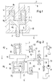
- differential plunger 1 is arranged in the press frame 10 and has an outwardly guided piston rod 2 to which a press bear, not shown, can be coupled.
- a pressure medium can be introduced into a lower cylinder chamber 6 via a hydraulic feed line 9.
- the hydraulic fluid acts on the annular, effective piston surface A3 in the upward direction and moves the piston 1 against the pressing direction.
- the piston surface opposite the piston surface A3 can be pressurized.
- This opposite piston surface is divided into the sub-areas A1 and A2.
- the partial area A 1 is annular and lies on the annular cylinder chamber 4, which can be supplied with pressure medium via the hydraulic line 8.
- the partial area A2 is in the interior of the piston 1 at the bottom of a cylinder chamber 5.
- the piston projecting into this cylinder chamber 5 is designed as a plunger 3 and rigidly connected to the press frame 10.
- the partial area A2 effective in the downward direction corresponds to the size of the end face of the plunger 3.
- the cylinder / piston system 5, 3 represents a kinematic reversal of a normal hydraulic cylinder system, since the plunger 3 is held in place while the machine part (piston 1) moves.
- a hydraulic line 7 is guided through the fixed plunger 3.
- the differential plunger system shown can be switched hydraulically in such a way that the hydraulic fluid displaced from a cylinder space in rapid traverse is used to fill up another enlarging cylinder space. This is easily possible due to the dimensioning of the effective piston areas A1, A2, A3.
- the piston area A3 is larger than each of the two individual partial areas A1 and A2.
- A3 is smaller than the sum of the two partial areas A1 and A2.
- all three cylinder rooms 4, 5, 6 with their hydraulic lines 7, 8, 9 can be connected to a common pressure medium supply line of a hydraulic pump. Since the piston surfaces A1 and A2, which act in the pressing direction, together are larger than the piston surface A3 effective in the opposite direction, the piston 3 moves downwards because of the almost identical pressure everywhere, the hydraulic fluid displaced from the lower cylinder chamber 6 through the existing line connections gets into the upper cylinder rooms 4 and 5. This means that the hydraulic pump only has to fill the cylinder volume corresponding to the area size 1, so that a high speed can be achieved. When driving slowly downwards, the hydraulic fluid displaced from the lower cylinder space 6 is conveyed into the hydraulic tank and the upper cylinder spaces 4 and 5 are filled solely by the hydraulic pump. In this case, the full pressing force in the pressing direction is available (corresponding to the effective piston area A1 + A2).
- Another circuit for the rapid downward movement would be that the cylinder spaces 5 and 6 are connected to one another by appropriate valve circuits and in addition to deriving the excess hydraulic fluid from the hydraulic tank, while the hydraulic pump is only connected to the cylinder space 4.
- the hydraulic pump is only connected to the cylinder space 4.
- the cylinder chambers 5 and 6 can be connected to one another and to the hydraulic pump by means of a suitable valve circuit, while the cylinder chamber 4 is connected to the hydraulic tank.
- the cylinder chamber 4 is connected to the hydraulic tank.
- the predominant part is conveyed from the cylinder chamber 5 into the cylinder chamber 6 by the displacement of the hydraulic fluid.
- the upper cylinder spaces 4 and 5 can be connected to the hydraulic tank and the lower cylinder space 6 to the hydraulic pump. In such a case, however, only the pressing force corresponding to an effective piston surface of size 5 is available (instead of 6 in the downward direction). At the same time, of course, there is a corresponding reduction in the possible speed.
- Such a differential plunger system has other disadvantages in addition to the complex design.
- Such a limit is practically a ratio of the piston area A3 to the piston rod cross section 2 of 6: 1, this means that there is also a corresponding restriction for the ratio of maximum rapid traverse speed and working gear speed.
- the entire pressing force must be transferred to the press bar via the piston rod 2, so that the piston rod is subjected to high mechanical stresses and the introduction of force into the press bar is difficult.
- such a hydraulic piston system is not very suitable for assuming management functions for the press bear, i.e. to absorb lateral forces.
- the distance between the contact zones of the piston rod 2 and the piston 1 with the press frame 10 becomes smaller and smaller as the press bear extends downward, so that there is an increasingly weaker lateral guidance in the pressing direction, that is to say with increasing pressing force.
- this construction offers no protection against rotation of the press bear about the longitudinal axis lying in the pressing direction.
- such a construction does not allow a hydraulic auxiliary piston, as is often required in metal powder presses, to be integrated into the piston rod 2.
- the object of the invention is to develop a press according to the preamble of claim 1 with a view to achieving short cycle times so that, in comparison to the working speed, very high and roughly equal rapid traverse speeds are possible in both directions, the force being introduced by the hydraulic cylinder / piston System in the press bear with a view to lower stress on the piston rod or piston rods should be improved.
- the construction effort and the energy input when operating the press should remain as low as possible.
- the design according to the invention provides a hydraulic press which enables rapid traverse speeds in excess of 0.5 m / sec without requiring a "suction operation".
- the great advantage here is that a precise position controllability is always ensured in the work step, that is to say when the press bear is moved slowly with a high pressing force. In contrast to punching or embossing presses, this is of great importance for a powder press.
- the desired end position of the press ram must not only be controlled precisely but also at a sufficiently slow speed so that the powder to be pressed has enough time to flow in the molding space, so that pressed parts with a uniform density are produced.
- the section shown in FIG. 1 from a known hydraulic press drive has already been explained in detail above.
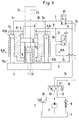
- the press drive according to the invention which is shown schematically in FIG. 2, has significant differences.
- the press bear 11 is firmly coupled to the piston rods of two cylinder / piston units K1 and K2.
- the lower unit K1 is equipped with a double-acting piston 13.
- the associated effective piston area A 1 (downward direction) is smaller than the piston area A 3 of the piston 13 (upward direction) associated with the cylinder chamber 6.
- the cylinder / piston unit K2 On the opposite side of the press bear 11 is the cylinder / piston unit K2, which has a plunger 12 with the effective piston area A2 (downward direction).
- the (here directed downwards) effective piston surfaces A1 and A2 are distributed to two cylinder / piston units K1, K2, which are not nested like in Fig. 1.
- the surfaces A1 and A2 are individually smaller than A3 , but together greater than A3. For this reason, the downward direction will normally be considered the pressing direction. In individual cases, however, it can also be expedient to choose the direction with the smaller effective piston area, that is to say the lower maximum pressing force that can be achieved, as the pressing direction.
- the same drive units could be used to build a press with lower output as for building a larger press.
- the hydraulic / cylinder units K1 and K2 can be arranged on the same side of the press bear 11.
- the drive system according to the invention can be used for upper and lower bears of hydraulic presses.
- the pressure medium supply to the cylinder spaces 4, 5, 6 via the hydraulic lines 7, 8, 9 is controlled by the valves V1, V2, V3.
- the function is as follows:
- the hydraulic pump P delivers hydraulic fluid from a hydraulic tank T under excess pressure through a hydraulic line 19.
- This hydraulic line 19 leads to a 4/3-way valve V 1, which blocks all line connections in position b.
- V 1 the delivered hydraulic fluid from line 19 via line 20, which is secured by a pressure relief valve S (circulation valve), back into the hydraulic tank.
- S pressure relief valve
- the hydraulic valve V 1 If the hydraulic valve V 1 is now moved into position a, the hydraulic fluid passes through the hydraulic lines 14 and 8 into the cylinder space 4 of the hydraulic / piston unit K 1. Since the 3/2-way valve V3 is in switch position b, there is a line connection between the cylinder spaces 4 and 6 via the hydraulic lines 8, 21, 9.
- the cylinder chamber 5 of the upper hydraulic / piston unit K2 is not acted upon by the pressure of the hydraulic pump P because of the valve position b on the 3/2-way valve V2, but is in position a of the valve V1 via lines 7, 16 and 18 with the Hydraulic tank T connected so that the hydraulic fluid displaced from the cylinder chamber 5 can flow into the hydraulic tank T via the check valve R.
- a high downward speed occurs when the valve V1 remains in position a and valve V3 in position b, but valve V2 is moved into position a.
- a slow downward speed with high pressing force occurs when the valves V1 and V2 remain in position a and valve V3 is brought into position a.
- This case corresponds to switching situation number 1 according to the table.
- the other switching options listed in the table do not need to be discussed in detail here. It can be seen, however, that there are several switching options for the rapid traverse and the creep speed, depending on the direction of movement, which are each associated with different achievable maximum press speeds or maximum achievable press force and can therefore be more or less useful depending on the circumstances. This also applies to the various standstill positions, the selection of which can be made in a more or less favorable form with regard to subsequent switching positions for movement of the press bear.
- FIG. 2 An embodiment of the invention which is more suitable for practical use is shown in FIG.
- the basic function of the press drive, in particular the valve circuit, for which there are, of course, other solutions, is in accordance with the basic diagram according to FIG. 2, so that there is no need to go into this again. Therefore, only the differences are essentially explained.
- the hydraulic drives of the illustrated upper bear 11 of the hydraulic press are all connected to the upper side of the press bear 11.
- the double-acting cylinder / piston unit 13 is equipped with two piston rods.
- the lower piston rod is connected to the press bear 11, while the upper one is led out of the press frame 10 without a force transmission function.
- the upper piston rod is only necessary to keep the piston area A 1 smaller than the piston area A 3 on the piston 13 in order to operate K 1 as a differential piston system.
- FIG. 3 also shows that a double-acting hydraulic auxiliary piston system 22 can be installed in the piston rod of the piston 13, the pressure medium being supplied via the hydraulic lines 23, 24 through the upper piston rod of the piston 13. Such a possibility does not exist in the known system according to FIG. 1.
- the ratio of the piston area A2 or A 2a + A 2b of the plunger piston system K2 or K 2a , K 2b to the difference between the piston areas A3 - A1 of the differential piston system K1 is to be regarded as a useful guideline for dimensioning the piston areas; this ratio should be in the range 1.8: 1 to 2.5: 1, preferably 2: 1.
- a great advantage of the embodiment according to Figure 3 is that not only the integration of an auxiliary piston system 22 is possible, but that the cylinder / piston system K 1 has very good guiding properties for absorbing lateral forces, because the effective contact zones between the press frame for support 10 and the upper and lower piston rods of the piston 13 have a very large distance which does not change when the piston 13 is moved.
- This system is thus clearly superior to the known solution from FIG. 1. This also applies to the introduction of the pressing forces into the press bears, which is completely unproblematic due to the force distribution over several hydraulic piston units and the comparatively very large diameter of the piston rod of the piston 13.
- the drive system according to the invention enables not only the generation of high pressing forces during slow travel but also extremely high rapid traverse speeds without the expenditure of the hydraulic system being high during the various operating phases in a pressing cycle with a uniform utilization of the capacity and the power of the hydraulic pump used.
- the arrangement of the cylinder / piston systems K 2a and K 2b provides an absolute anti-rotation device for the press bear from the outset.
- a press part made of iron powder with a cycle time for filling the press tool with iron powder, pressing and shaping the press part totaling 3 seconds was produced on a press according to FIG. 3 with a pressing force of 150 t .
- the travel of the upper piston to the press end position consisted of approx. 275 mm in rapid traverse and 25 mm in the work cycle.
- the 300 mm return stroke was again carried out in rapid traverse.
- the cycle time accounted for about 0.5 seconds each for the drive in the work cycle and the two rapid traverse runs, i.e. about half the cycle time was determined by the movement of the upper piston.
- the rapid traverse would have had to take at least 1 second due to the large amounts of pressure medium to be sucked in. This would have meant that the cycle time would have been 4 seconds instead of 3 seconds, which would have been 33% higher.
Landscapes
- Engineering & Computer Science (AREA)
- Mechanical Engineering (AREA)
- Press Drives And Press Lines (AREA)
- Control Of Presses (AREA)
- Casting Or Compression Moulding Of Plastics Or The Like (AREA)
- Powder Metallurgy (AREA)
Applications Claiming Priority (2)
| Application Number | Priority Date | Filing Date | Title |
|---|---|---|---|
| DE4106639 | 1991-02-28 | ||
| DE4106639A DE4106639A1 (de) | 1991-02-28 | 1991-02-28 | Hydraulische presse fuer pulverfoermige massen |
Publications (3)
| Publication Number | Publication Date |
|---|---|
| EP0501596A2 true EP0501596A2 (fr) | 1992-09-02 |
| EP0501596A3 EP0501596A3 (en) | 1993-02-03 |
| EP0501596B1 EP0501596B1 (fr) | 1995-03-15 |
Family
ID=6426293
Family Applications (1)
| Application Number | Title | Priority Date | Filing Date |
|---|---|---|---|
| EP92250033A Expired - Lifetime EP0501596B1 (fr) | 1991-02-28 | 1992-02-18 | Presse hydraulique pour matière pulvérulentes |
Country Status (3)
| Country | Link |
|---|---|
| EP (1) | EP0501596B1 (fr) |
| AT (1) | ATE119829T1 (fr) |
| DE (2) | DE4106639A1 (fr) |
Cited By (3)
| Publication number | Priority date | Publication date | Assignee | Title |
|---|---|---|---|---|
| CN102380546A (zh) * | 2010-09-06 | 2012-03-21 | 刘家辉 | 多功能压力机 |
| CN102825122A (zh) * | 2012-09-25 | 2012-12-19 | 郑州金泰制罐有限公司 | 气动翻边机 |
| EP3115190A1 (fr) * | 2015-07-06 | 2017-01-11 | Feintool International Holding AG | Dispositif et procede de commande de l'entrainement principal d'une presse pour decoupage de precision |
Families Citing this family (2)
| Publication number | Priority date | Publication date | Assignee | Title |
|---|---|---|---|---|
| DE19643396B4 (de) * | 1996-10-21 | 2008-09-11 | Dieffenbacher Gmbh + Co. Kg | Hydraulische Steuereinrichtung |
| DE10241332B4 (de) * | 2001-09-25 | 2007-05-10 | Sms Meer Gmbh | Presse zum Einformen von Großrohren |
Family Cites Families (9)
| Publication number | Priority date | Publication date | Assignee | Title |
|---|---|---|---|---|
| US2354003A (en) * | 1942-07-15 | 1944-07-18 | Hydraulic Dev Corp Inc | Hydraulic press |
| FR1517290A (fr) * | 1967-03-30 | 1968-03-15 | Presse hydraulique notamment pour le traitement de métaux par formage | |
| US3635152A (en) * | 1969-12-04 | 1972-01-18 | Olmsted Products Co | Hydraulic press |
| DE2555939A1 (de) * | 1975-12-12 | 1977-06-23 | Mueller Ernst Dr Ing E H | Doppelt wirkende hydraulische gesenku. schmiedepresse fuer sehr hohe presskraefte |
| DE2715188A1 (de) * | 1977-04-05 | 1978-10-12 | Smg Sueddeutsche Maschinenbau | Presse mit einem arbeitshub vorgeschaltetem leerhub |
| DE2747548C2 (de) * | 1977-10-22 | 1986-04-17 | Thyssen Industrie Ag, 4300 Essen | Presse mit Regelkreis |
| DE3511205A1 (de) * | 1984-11-22 | 1986-05-28 | Manfred 8751 Niedernberg Wanzke | Hydraulische presse zur realisierung beliebiger pressdiagramme |
| JPS63256300A (ja) * | 1987-04-13 | 1988-10-24 | Nikkei:Kk | 粉末成形用油圧プレス |
| ES2021657B3 (es) * | 1987-09-02 | 1991-11-16 | Theodor Grabener Pressensysteme Gmbh & Co Kg | Prensa para producir piezas prensadas de material pulveriforme. |
-
1991
- 1991-02-28 DE DE4106639A patent/DE4106639A1/de not_active Withdrawn
-
1992
- 1992-02-18 AT AT92250033T patent/ATE119829T1/de not_active IP Right Cessation
- 1992-02-18 DE DE59201628T patent/DE59201628D1/de not_active Expired - Fee Related
- 1992-02-18 EP EP92250033A patent/EP0501596B1/fr not_active Expired - Lifetime
Cited By (3)
| Publication number | Priority date | Publication date | Assignee | Title |
|---|---|---|---|---|
| CN102380546A (zh) * | 2010-09-06 | 2012-03-21 | 刘家辉 | 多功能压力机 |
| CN102825122A (zh) * | 2012-09-25 | 2012-12-19 | 郑州金泰制罐有限公司 | 气动翻边机 |
| EP3115190A1 (fr) * | 2015-07-06 | 2017-01-11 | Feintool International Holding AG | Dispositif et procede de commande de l'entrainement principal d'une presse pour decoupage de precision |
Also Published As
| Publication number | Publication date |
|---|---|
| EP0501596A3 (en) | 1993-02-03 |
| EP0501596B1 (fr) | 1995-03-15 |
| DE4106639A1 (de) | 1992-09-10 |
| DE59201628D1 (de) | 1995-04-20 |
| ATE119829T1 (de) | 1995-04-15 |
Similar Documents
| Publication | Publication Date | Title |
|---|---|---|
| AT505724B1 (de) | Antriebsvorrichtung für eine biegepresse | |
| EP0972631B1 (fr) | Entraínement hydraulique pour une presse | |
| DE102012015118B3 (de) | Maschinenpresse | |
| EP0785861A1 (fr) | Systeme d'entrainement hydraulique pour une presse | |
| DE3202254A1 (de) | Verfahren und vorrichtung zur herstellung einer zahnstange | |
| WO2011035828A1 (fr) | Entraînement hydraulique précontraint doté d'une pompe à vitesse variable | |
| DE1577188A1 (de) | Hydraulische Druckerzeugungsanlage mit doppelt wirkendem Druckuebersetzer | |
| EP0501596B1 (fr) | Presse hydraulique pour matière pulvérulentes | |
| DE102020102378B4 (de) | Antriebsvorrichtung für eine Formgebungsmaschine und Formgebungsmaschine | |
| EP0629455A1 (fr) | Entraînement principal pour press à refouler | |
| DE4218953B4 (de) | Hydraulischer Pressenantrieb, insbesondere für eine Blechformpresse | |
| EP0850752B1 (fr) | Presse à étages multiples | |
| EP0751842B1 (fr) | Presse double | |
| EP3774316B1 (fr) | Entraînement de presse à récupération d'énergie | |
| DE4302263A1 (de) | Mechanische Stufenpresse mit hydraulischen Arbeitshubeinheiten | |
| EP0214498A1 (fr) | Presse mécanique, en particulier presse à genouillère | |
| EP2114587B1 (fr) | Presse de formage présentant une fonction de coussin pneumatique intégrée au plateau coulissant | |
| EP0829318B1 (fr) | Procédé de réglage de fréquence de la course du coulisseau dans une presse de forgeage et presse de forgeage pour la mise en oeuvre de ce procédé | |
| EP0586028B1 (fr) | Presse pour fabriquer des articles pressés à dimensions exactes | |
| DE19643396B4 (de) | Hydraulische Steuereinrichtung | |
| DE907241C (de) | Hydraulisches Getriebe fuer Stossmaschinen | |
| EP3338909B1 (fr) | Dispositif d'estampage | |
| DE1145018B (de) | Schnellarbeitende hydraulische Presse, insbesondere Schmiedepresse oder Ziehpresse | |
| EP1199277A1 (fr) | Plateforme de levage pour un véhicule | |
| DE29917742U1 (de) | Presse mit Exzenterkurbeltrieb für Oberstempeleinheit |
Legal Events
| Date | Code | Title | Description |
|---|---|---|---|
| PUAI | Public reference made under article 153(3) epc to a published international application that has entered the european phase |
Free format text: ORIGINAL CODE: 0009012 |
|
| AK | Designated contracting states |
Kind code of ref document: A2 Designated state(s): AT CH DE FR IT LI |
|
| PUAL | Search report despatched |
Free format text: ORIGINAL CODE: 0009013 |
|
| AK | Designated contracting states |
Kind code of ref document: A3 Designated state(s): AT CH DE FR IT LI |
|
| 17P | Request for examination filed |
Effective date: 19930211 |
|
| 17Q | First examination report despatched |
Effective date: 19940428 |
|
| GRAA | (expected) grant |
Free format text: ORIGINAL CODE: 0009210 |
|
| ITF | It: translation for a ep patent filed | ||
| AK | Designated contracting states |
Kind code of ref document: B1 Designated state(s): AT CH DE FR IT LI |
|
| REF | Corresponds to: |
Ref document number: 119829 Country of ref document: AT Date of ref document: 19950415 Kind code of ref document: T |
|
| ET | Fr: translation filed | ||
| REF | Corresponds to: |
Ref document number: 59201628 Country of ref document: DE Date of ref document: 19950420 |
|
| PLBE | No opposition filed within time limit |
Free format text: ORIGINAL CODE: 0009261 |
|
| 26N | No opposition filed | ||
| REG | Reference to a national code |
Ref country code: CH Ref legal event code: PFA Owner name: MANNESMANN AKTIENGESELLSCHAFT Free format text: MANNESMANN AKTIENGESELLSCHAFT#MANNESMANNUFER 2#D-40213 DUESSELDORF 1 (DE) -TRANSFER TO- MANNESMANN AKTIENGESELLSCHAFT#MANNESMANNUFER 2#D-40213 DUESSELDORF 1 (DE) |
|
| PGFP | Annual fee paid to national office [announced via postgrant information from national office to epo] |
Ref country code: AT Payment date: 20090218 Year of fee payment: 18 |
|
| PGFP | Annual fee paid to national office [announced via postgrant information from national office to epo] |
Ref country code: DE Payment date: 20090219 Year of fee payment: 18 |
|
| PGFP | Annual fee paid to national office [announced via postgrant information from national office to epo] |
Ref country code: CH Payment date: 20090217 Year of fee payment: 18 |
|
| PGFP | Annual fee paid to national office [announced via postgrant information from national office to epo] |
Ref country code: IT Payment date: 20090221 Year of fee payment: 18 |
|
| PGFP | Annual fee paid to national office [announced via postgrant information from national office to epo] |
Ref country code: FR Payment date: 20090213 Year of fee payment: 18 |
|
| REG | Reference to a national code |
Ref country code: CH Ref legal event code: PL |
|
| PG25 | Lapsed in a contracting state [announced via postgrant information from national office to epo] |
Ref country code: CH Free format text: LAPSE BECAUSE OF NON-PAYMENT OF DUE FEES Effective date: 20100228 Ref country code: LI Free format text: LAPSE BECAUSE OF NON-PAYMENT OF DUE FEES Effective date: 20100228 |
|
| REG | Reference to a national code |
Ref country code: FR Ref legal event code: ST Effective date: 20101029 |
|
| PG25 | Lapsed in a contracting state [announced via postgrant information from national office to epo] |
Ref country code: AT Free format text: LAPSE BECAUSE OF NON-PAYMENT OF DUE FEES Effective date: 20100218 |
|
| PG25 | Lapsed in a contracting state [announced via postgrant information from national office to epo] |
Ref country code: FR Free format text: LAPSE BECAUSE OF NON-PAYMENT OF DUE FEES Effective date: 20100301 |
|
| PG25 | Lapsed in a contracting state [announced via postgrant information from national office to epo] |
Ref country code: DE Free format text: LAPSE BECAUSE OF NON-PAYMENT OF DUE FEES Effective date: 20100901 |
|
| PG25 | Lapsed in a contracting state [announced via postgrant information from national office to epo] |
Ref country code: IT Free format text: LAPSE BECAUSE OF NON-PAYMENT OF DUE FEES Effective date: 20100218 |