EP0503592B1 - Getriebe mit hydrostatischen Motoren, insbesondere für Erdbewegungsmaschinen - Google Patents
Getriebe mit hydrostatischen Motoren, insbesondere für Erdbewegungsmaschinen Download PDFInfo
- Publication number
- EP0503592B1 EP0503592B1 EP92104179A EP92104179A EP0503592B1 EP 0503592 B1 EP0503592 B1 EP 0503592B1 EP 92104179 A EP92104179 A EP 92104179A EP 92104179 A EP92104179 A EP 92104179A EP 0503592 B1 EP0503592 B1 EP 0503592B1
- Authority
- EP
- European Patent Office
- Prior art keywords
- gearwheel
- gearwheels
- countershaft
- input
- gearbox
- Prior art date
- Legal status (The legal status is an assumption and is not a legal conclusion. Google has not performed a legal analysis and makes no representation as to the accuracy of the status listed.)
- Expired - Lifetime
Links
- 230000002706 hydrostatic effect Effects 0.000 title claims abstract description 42
- 230000005540 biological transmission Effects 0.000 claims abstract description 8
- 238000006073 displacement reaction Methods 0.000 claims description 26
- 230000008878 coupling Effects 0.000 claims description 2
- 238000010168 coupling process Methods 0.000 claims description 2
- 238000005859 coupling reaction Methods 0.000 claims description 2
- 238000001514 detection method Methods 0.000 claims description 2
- 238000006243 chemical reaction Methods 0.000 description 10
- 230000035939 shock Effects 0.000 description 5
- 230000014509 gene expression Effects 0.000 description 4
- 238000010586 diagram Methods 0.000 description 3
- 230000009977 dual effect Effects 0.000 description 2
- 230000007935 neutral effect Effects 0.000 description 2
- 230000006978 adaptation Effects 0.000 description 1
- 230000002860 competitive effect Effects 0.000 description 1
- 230000000670 limiting effect Effects 0.000 description 1
- 238000004519 manufacturing process Methods 0.000 description 1
- 230000004048 modification Effects 0.000 description 1
- 238000012986 modification Methods 0.000 description 1
- 230000003287 optical effect Effects 0.000 description 1
- 238000004513 sizing Methods 0.000 description 1
- 230000001360 synchronised effect Effects 0.000 description 1
Images
Classifications
-
- F—MECHANICAL ENGINEERING; LIGHTING; HEATING; WEAPONS; BLASTING
- F16—ENGINEERING ELEMENTS AND UNITS; GENERAL MEASURES FOR PRODUCING AND MAINTAINING EFFECTIVE FUNCTIONING OF MACHINES OR INSTALLATIONS; THERMAL INSULATION IN GENERAL
- F16H—GEARING
- F16H61/00—Control functions within control units of change-speed- or reversing-gearings for conveying rotary motion ; Control of exclusively fluid gearing, friction gearing, gearings with endless flexible members or other particular types of gearing
- F16H61/38—Control of exclusively fluid gearing
- F16H61/40—Control of exclusively fluid gearing hydrostatic
- F16H61/44—Control of exclusively fluid gearing hydrostatic with more than one pump or motor in operation
- F16H61/444—Control of exclusively fluid gearing hydrostatic with more than one pump or motor in operation by changing the number of pump or motor units in operation
-
- F—MECHANICAL ENGINEERING; LIGHTING; HEATING; WEAPONS; BLASTING
- F16—ENGINEERING ELEMENTS AND UNITS; GENERAL MEASURES FOR PRODUCING AND MAINTAINING EFFECTIVE FUNCTIONING OF MACHINES OR INSTALLATIONS; THERMAL INSULATION IN GENERAL
- F16H—GEARING
- F16H47/00—Combinations of mechanical gearing with fluid clutches or fluid gearing
- F16H47/02—Combinations of mechanical gearing with fluid clutches or fluid gearing the fluid gearing being of the volumetric type
-
- F—MECHANICAL ENGINEERING; LIGHTING; HEATING; WEAPONS; BLASTING
- F16—ENGINEERING ELEMENTS AND UNITS; GENERAL MEASURES FOR PRODUCING AND MAINTAINING EFFECTIVE FUNCTIONING OF MACHINES OR INSTALLATIONS; THERMAL INSULATION IN GENERAL
- F16H—GEARING
- F16H61/00—Control functions within control units of change-speed- or reversing-gearings for conveying rotary motion ; Control of exclusively fluid gearing, friction gearing, gearings with endless flexible members or other particular types of gearing
- F16H61/38—Control of exclusively fluid gearing
- F16H61/40—Control of exclusively fluid gearing hydrostatic
- F16H61/42—Control of exclusively fluid gearing hydrostatic involving adjustment of a pump or motor with adjustable output or capacity
- F16H61/421—Motor capacity control by electro-hydraulic control means, e.g. using solenoid valves
-
- F—MECHANICAL ENGINEERING; LIGHTING; HEATING; WEAPONS; BLASTING
- F16—ENGINEERING ELEMENTS AND UNITS; GENERAL MEASURES FOR PRODUCING AND MAINTAINING EFFECTIVE FUNCTIONING OF MACHINES OR INSTALLATIONS; THERMAL INSULATION IN GENERAL
- F16H—GEARING
- F16H61/00—Control functions within control units of change-speed- or reversing-gearings for conveying rotary motion ; Control of exclusively fluid gearing, friction gearing, gearings with endless flexible members or other particular types of gearing
- F16H61/38—Control of exclusively fluid gearing
- F16H61/40—Control of exclusively fluid gearing hydrostatic
- F16H61/44—Control of exclusively fluid gearing hydrostatic with more than one pump or motor in operation
-
- F—MECHANICAL ENGINEERING; LIGHTING; HEATING; WEAPONS; BLASTING
- F16—ENGINEERING ELEMENTS AND UNITS; GENERAL MEASURES FOR PRODUCING AND MAINTAINING EFFECTIVE FUNCTIONING OF MACHINES OR INSTALLATIONS; THERMAL INSULATION IN GENERAL
- F16H—GEARING
- F16H3/00—Toothed gearings for conveying rotary motion with variable gear ratio or for reversing rotary motion
- F16H3/02—Toothed gearings for conveying rotary motion with variable gear ratio or for reversing rotary motion without gears having orbital motion
- F16H3/08—Toothed gearings for conveying rotary motion with variable gear ratio or for reversing rotary motion without gears having orbital motion exclusively or essentially with continuously meshing gears, that can be disengaged from their shafts
- F16H3/087—Toothed gearings for conveying rotary motion with variable gear ratio or for reversing rotary motion without gears having orbital motion exclusively or essentially with continuously meshing gears, that can be disengaged from their shafts characterised by the disposition of the gears
- F16H3/093—Toothed gearings for conveying rotary motion with variable gear ratio or for reversing rotary motion without gears having orbital motion exclusively or essentially with continuously meshing gears, that can be disengaged from their shafts characterised by the disposition of the gears with two or more countershafts
- F16H2003/0931—Toothed gearings for conveying rotary motion with variable gear ratio or for reversing rotary motion without gears having orbital motion exclusively or essentially with continuously meshing gears, that can be disengaged from their shafts characterised by the disposition of the gears with two or more countershafts each countershaft having an output gear meshing with a single common gear on the output shaft
-
- Y—GENERAL TAGGING OF NEW TECHNOLOGICAL DEVELOPMENTS; GENERAL TAGGING OF CROSS-SECTIONAL TECHNOLOGIES SPANNING OVER SEVERAL SECTIONS OF THE IPC; TECHNICAL SUBJECTS COVERED BY FORMER USPC CROSS-REFERENCE ART COLLECTIONS [XRACs] AND DIGESTS
- Y10—TECHNICAL SUBJECTS COVERED BY FORMER USPC
- Y10T—TECHNICAL SUBJECTS COVERED BY FORMER US CLASSIFICATION
- Y10T74/00—Machine element or mechanism
- Y10T74/19—Gearing
- Y10T74/19219—Interchangeably locked
- Y10T74/19233—Plurality of counter shafts
Definitions
- the present invention relates to a gearbox with hydrostatic motors particularly for earth-movers.
- c.r. tot (max. travel speed)/(maximum working speed under traction), which is limited to approximately nine times, using three times the adjustment of the hydrostatic pump and of the hydrostatic motor as degrees of freedom of the above expression.
- some earth-movers have a range for working speeds, comprised for example between 2 and 18 km/h, and another range for travel speeds, i.e. 4.25 to 38.2 km/h.
- Hydrostatic motors have recently appeared on the market which allow adjustments down to practically zero displacement, thus allowing almost a doubling of the adjustment of the motor, which allows to practically double the total conversion ratio, raising it up to approximately 18, by using a pair of constantly engaged twin motors and by setting one to zero at high speeds or by setting to zero and disconnecting one of the two when it has reached its maximum speed and leaving the other motor to continue on its own, and finally allowing to change gear with a normal synchromesh unit when the motor is in the zero-displacement condition and all the power flows onto the other motor.
- GB-A-974 532 discloses a speed change gear as defined in the preamble of the appended claim 1.
- the aim of the present invention is to eliminate or substantially reduce the problems described above in known types of gearboxes on earth-movers by providing a gearbox with hydrostatic motors particularly for earth-movers which does not require the setting to zero of one of the two motors.
- an object of the present invention is to provide a gearbox which allows to use any hydrostatic motor.
- Another object of the present invention is to provide a gearbox which allows easy and rapid gear shifts, eliminating the need to stop the earth-mover.
- Not least object of the present invention is to provide a gearbox which is relatively easy to manufacture and at competitive costs.
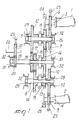
- a gearbox with hydrostatic motors particularly for earth-movers comprises a first hydrostatic motor 1 and a second hydrostatic motor 2, each of which has a respective output shaft 3 and 4.
- Each of the motors 1 and 2 has an either fixed or variable displacement, which can both be used with the gearbox according to the invention.
- the first hydrostatic motor 1 is connected to a first countershaft 5 by virtue of first transmission means which comprise a gearwheel 6 which is keyed on the output shaft 3 and meshes with a gearwheel 7 which is keyed on the first countershaft 5.
- the second hydrostatic motor 2 is connected to a second countershaft 8 by virtue of second transmission means which comprise a gearwheel 9 which is keyed on the output shaft 4 and meshes with a gearwheel 10 which is keyed on the second countershaft 8.
- the first countershaft 5 and the second countershaft 8 respectively support a plurality of input gearwheels, respectively designated by the reference numerals 11, 12, 13 and 14, which can be selectively coupled to the respective countershaft by virtue of selection means which comprise synchromesh units 15 for selectively coupling the gearwheels 11, 12, 13 and 14 to the respective countershafts 5 and 8.
- the gearwheels 11, 12, 13 and 14 mesh with respective secondary gearwheels 16, 17 and 18 in order to define gear ratios.
- Said secondary gearwheels 16, 17 and 18 are supported by a secondary shaft 19.
- the secondary gearwheels 17 and 18 are keyed to the secondary shaft 19, whereas the secondary gearwheel 16 can be selectively coupled to said secondary shaft by virtue of the synchromesh unit 15.
- a first output gearwheel 20 is keyed on the secondary shaft 19 and meshes with a second output gearwheel 21 which is keyed on an output shaft 22.
- the present invention comprises angular velocity detection means, constituted for example by optical sensors 23, arranged at each of the gearwheels 6 and 9 which are keyed on the respective output shafts 3 and 4 of the hydrostatic motors 1 and 2 and at the second output gearwheel 21.
- the gearbox furthermore comprises brake means 24 and 25 which are arranged on each output shaft 3 and 4 of the hydrostatic motors 1 and 2.
- the first countershaft 5, the second countershaft 8 and the secondary shaft 19 are supported by respective bearings 26, 27, 28, 29, 30 and 31 which are fixed to a frame 32 of the gearbox in order to allow the rotation of the countershafts 5 and 8 and of the secondary shaft 19.
- the described embodiment relates to a four-gear gearbox; the adaptations for gearboxes with a greater or smaller number of gear ratios are obvious.
- the conversion ratio of the gearbox as a whole is therefore equal to the ratio between the maximum and minimum displacements that the motors 1 and 2 are able to provide at each turn of the output shaft 22, considering the various gear ratios by means of the clutches and the kinematic trains defined by the previously described gearwheels.
- the motor 1 which has the smallest displacement of the two motors used, up to the point at which its gear ratios can be obtained mechanically and the obtained rotation rates do not exceed the limits set by the manufacturer of said motor.
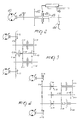
- a practical example of how to obtain gear shifting with minimized shocks and vibrations is the one shown in figure 2 for a single countershaft, which has a hydraulic motor 40 which has, on the output shaft, a brake 41, gear ratios 42 and 43, an electronic tachometer 44 and a dual hydraulic-controlled easy-shifted clutch 45, for example of the type with radial clutch by means of balls, actuated by a hydraulic actuator 46, such as a compressor or another similar hydraulic apparatus.
- the electronic control of the earth-mover allows the hydraulic actuator 46 to engage the easy-shifted clutch 45, and gear shifting is thus achieved.
- the hydraulic actuator 46 sets the chosen clutch to neutral, whereas the brake 41 reduces the rotation rate of the motor 40 until it is synchronized with the second gearwheel, the displacements are returned to their maximum values, the clutch 45 is engaged again and the brake 41 is released.
- the conversion ratio of the pump is thus set to 1.2 in order to provide an appropriate overlap to the phases and in order to reduce the size and/or costs of the hydrostatic pump.
- the total adjustment of the gearbox is thus 15.91.
- the gearbox according to the invention achieves the intended aim and objects, since advantageously the need to stop to change gear is eliminated, and furthermore since shocks or vibrations during power shifting are conveniently eliminated or minimized. Furthermore the need for different operating ranges for the earth-mover provided with a gearbox according to the invention is eliminated.
- the materials employed, as well as the dimensions, may be any according to the requirements.
Landscapes
- Engineering & Computer Science (AREA)
- General Engineering & Computer Science (AREA)
- Mechanical Engineering (AREA)
- Motor Power Transmission Devices (AREA)
- Structure Of Transmissions (AREA)
- Superconductive Dynamoelectric Machines (AREA)
- Treatment Of Fiber Materials (AREA)
- Soil Working Implements (AREA)
Claims (11)
- Getriebe mit hydrostatischen Motoren, insbesondere für Erdbewegungsmaschinen, mit einem ersten hydrostatischen Motor (1) und einem zweiten hydrostatischen Motor (2), welche eine selektiv fixierte und variable Verschiebung haben, wobei der erste hydrostatische Motor mit einer ersten Gegenwelle (5) mittels erster Transmissionsmittel (6,7) und der zweite hydrostatische Motor mit einer zweiten Gegenwelle (8) mittels zweiter Transmissionsmittel (9,10) verbunden ist, wobei die ersten und zweiten Gegenwellen eine Mehrzahl von Eingangszahnrädern (11-14) tragen, wobei die Mehrzahl der Zahnräder jeweils mit sekundären Zahnrädern (16-18) kämmen, um Übersetzungsverhältnisse zu definieren, wobei die sekundären Zahnräder von einer sekundären Welle (19) getragen werden, wobei dritte Transmissionsmittel (20,21) zur Verbindung der sekundären Welle mit einer Ausgangswelle (22) vorgesehen sind,
dadurch gekennzeichnet,
daß die Eingangszahnräder mit einer jeweiligen Gegenwelle mittels Auswahlmitteln (15) selektiv kuppelbar sind und daß die sekundären Zahnräder selektiv mit der sekundären Welle mittels der Auswahlmittel (15) kuppelbar sind. - Getriebe nach Anspruch 1,
dadurch gekennzeichnet,
daß die Eingangszahnräder ein erstes Eingangszahnrad (11) und ein zweites Eingangszahnrad (12) aufweisen, die beide von der ersten Gegenwelle (5) getragen sind, wobei die Eingangszahnräder außerdem ein drittes Eingangszahnrad (13) und ein viertes Eingangszahnrad (14) aufweisen, die beide von der zweiten Gegenwelle (8) getragen sind, wobei die sekundären Zahnräder ein erstes sekundäres Zahnrad (16), welches mit dem ersten Eingangszahnrad (11) und ebenfalls mit dem dritten Eingangszahnrad (13) kämmt, ein zweites sekundäres Zahnrad (17), welches mit dem vierten Eingangszahnrad (14) kämmt, und ein drittes sekundäres Zahnrad (18) einschließen, welches mit dem zweiten Eingangszahnrad (12) kämmt. - Getriebe nach Anspruch 2,
dadurch gekennzeichnet,
daß das erste sekundäre Zahnrad (16) selektiv mit der sekundären Welle mittels der Auswahlmittel (15) kuppelbar ist, und daß das zweite und dritte sekundäre Zahnrad (17,18) fest auf der sekundären Welle befestigt sind. - Getriebe nach irgendeinem der vorangehenden Ansprüche,
dadurch gekennzeichnet,
daß die ersten Transmissionsmittel ein Zahnrad (6) aufweisen, welches auf einer Austrittswelle (3) des ersten hydrostatischen Motors (1) befestigt ist, und welches mit einem Zahnrad (7) kämmt, welches auf der ersten Gegenwelle (5) befestigt ist. - Getriebe nach irgendeinem der vorangehenden Ansprüche,
dadurch gekennzeichnet,
daß die zweiten Transmissionsmittel ein Zahnrad (9) aufweisen, welches auf einer Ausgangswelle (4) des zweiten hydrostatischen Motors (2) befestigt ist, und welches mit einem Zahnrad (10) kämmt, welches auf der zweiten Gegenwelle (8) befestigt ist. - Getriebe nach einem oder mehreren der vorangehenden Ansprüche,
dadurch gekennzeichnet,
daß die Auswahlmittel Synchrongetriebeeinheiten (15) aufweisen, die geeignet sind, selektiv Zahnräder mit ihren jeweiligen Wellen und Gegenwellen zu kuppeln. - Getriebe nach einem oder mehreren der vorangehenden Ansprüche,
dadurch gekennzeichnet,
daß die Mehrzahl der Eingangszahnräder wenigstens ein Paar (11,12 bzw. 13,14) von Eingangszahnrädern auf jeder Gegenwelle (5 bzw. 8) aufweisen. - Getriebe nach einem oder mehreren der vorangehenden Ansprüche,
dadurch gekennzeichnet,
daß es wenigstens ein sekundäres Zahnrad (16-18) für jedes Eingangszahnrad (11-14) aufweist, wobei jedes sekundäre Zahnrad selektiv befestigt und fest mit der sekundären Welle (19) verbunden ist. - Getriebe nach einem oder mehreren der vorangehenden Ansprüche,
dadurch gekennzeichnet,
daß es Winkelgeschwindigkeitsdetektormittel (23) an jedem der Zahnräder aufweist, welche auf den Ausgangswellen (3,4) der ersten (1) und zweiten (2) hydrostatischen Motoren und auf der zweiten Ausgangswelle (22) befestigt sind. - Getriebe nach einem oder mehreren der vorangehenden Ansprüche,
dadurch gekennzeichnet,
daß es Bremsmittel (24,25) aufweist, welche auf jeder der Ausgangswellen der ersten (1) und zweiten (2) hydrostatischen Motoren angeordnet sind. - Getriebe nach einem oder mehreren der vorangehenden Ansprüche,
dadurch gekennzeichnet,
daß die erste Gegenwelle (5), die zweite Gegenwelle (8) und die sekundäre Welle (19) von Lagern (26-31) getragen sind, welche an einem Rahmen (32) des Getriebes befestigt sind und geeignet sind, die Rotation der Gegenwellen und der sekundären Welle zu erlauben.
Applications Claiming Priority (2)
| Application Number | Priority Date | Filing Date | Title |
|---|---|---|---|
| ITMI910698 | 1991-03-15 | ||
| ITMI910698A IT1245204B (it) | 1991-03-15 | 1991-03-15 | Cambio di velocita' a motori idrostatici particolarmente per macchine movimento terra |
Publications (2)
| Publication Number | Publication Date |
|---|---|
| EP0503592A1 EP0503592A1 (de) | 1992-09-16 |
| EP0503592B1 true EP0503592B1 (de) | 1995-06-14 |
Family
ID=11359063
Family Applications (1)
| Application Number | Title | Priority Date | Filing Date |
|---|---|---|---|
| EP92104179A Expired - Lifetime EP0503592B1 (de) | 1991-03-15 | 1992-03-11 | Getriebe mit hydrostatischen Motoren, insbesondere für Erdbewegungsmaschinen |
Country Status (5)
| Country | Link |
|---|---|
| US (1) | US5388450A (de) |
| EP (1) | EP0503592B1 (de) |
| AT (1) | ATE123852T1 (de) |
| DE (1) | DE69202887T2 (de) |
| IT (1) | IT1245204B (de) |
Families Citing this family (14)
| Publication number | Priority date | Publication date | Assignee | Title |
|---|---|---|---|---|
| EP0469451B1 (de) * | 1990-07-25 | 1997-02-05 | CLARK-HURTH COMPONENTS S.p.A. | Getriebe mit drei parallelen Wellen, insbesondere für Nutzfahrzeuge |
| DE4416930A1 (de) * | 1994-05-13 | 1995-11-16 | Zahnradfabrik Friedrichshafen | Unter Last schaltbares, mehrgängiges Wendegetriebe |
| GB9602509D0 (en) * | 1996-02-07 | 1996-04-03 | Komatsu Uk Ltd | Control system for hydraulic drive |
| DE10109775A1 (de) * | 2001-03-01 | 2002-09-12 | Deere & Co | Antriebssystem eines Arbeitsfahrzeugs |
| US7243755B2 (en) * | 2004-07-28 | 2007-07-17 | Zf Friedrichshafen Ag | Drive mechanism for a mobile vehicle |
| US7299891B2 (en) * | 2004-08-02 | 2007-11-27 | Zf Friedrichshafen Ag | Hydraulic drive mechanism for mobile vehicles |
| US7201702B2 (en) * | 2004-08-02 | 2007-04-10 | Zf Friedrichshafen Ag | Drive mechanism for a mobile vehicle |
| EP1630030A3 (de) * | 2004-08-24 | 2008-04-09 | Kanzaki Kokyukoki MFG. Co., Ltd. | Pumpensystem und Achsantriebssystem |
| US7637101B2 (en) | 2005-03-10 | 2009-12-29 | Tcm Corporation | Hydraulic power transmission device and work vehicle |
| WO2007010743A1 (ja) * | 2005-07-22 | 2007-01-25 | Komatsu Ltd. | 走行車両の無段変速装置及びその無段変速方法 |
| DE102007038175A1 (de) * | 2007-08-13 | 2009-02-19 | Magna Powertrain Ag & Co Kg | Schaltgetriebe |
| JP5301509B2 (ja) * | 2010-08-31 | 2013-09-25 | 日立建機株式会社 | 作業車両の走行制御装置 |
| DE102016207299A1 (de) * | 2016-04-28 | 2017-11-02 | Zf Friedrichshafen Ag | Unter Last schaltbares mehrgängiges Wendegetriebe |
| KR102435067B1 (ko) * | 2017-12-22 | 2022-08-22 | 주식회사 디엔솔루션즈 | 공작기계의 주축 구동장치 |
Family Cites Families (43)
| Publication number | Priority date | Publication date | Assignee | Title |
|---|---|---|---|---|
| DE887663C (de) * | 1951-05-11 | 1953-08-24 | Eisen & Stahlind Ag | Einrichtung zur Umkehrung der Fahrtrichtung eines Schienenfahrzeuges mit Einzelachsantrieb |
| US2943503A (en) * | 1952-06-20 | 1960-07-05 | Daimler Benz Ag | Automobile transmission |
| US3199378A (en) * | 1961-06-09 | 1965-08-10 | Cambi Idraulici Badalini Spa | Continuous hydraulic speed change gear with two speed ranges having different amplitudes for vehicles |
| US3166952A (en) * | 1961-10-19 | 1965-01-26 | Richard E Lang | Drive systems |
| US3213712A (en) * | 1963-08-08 | 1965-10-26 | Int Harvester Co | Hydromechanical transmission with countershaft gearing |
| FR1456078A (fr) * | 1965-09-09 | 1966-05-20 | Richier Sa | Dispositif d'actionnement d'un arbre récepteur par une pompe hydraulique volumétrique |
| US3468192A (en) * | 1966-10-03 | 1969-09-23 | Algirdas L Nasvytis | Transmission |
| US3492891A (en) * | 1968-07-03 | 1970-02-03 | Gen Motors Corp | Single speed range input-split-power drive,multispeed range compound-split-power drive,power train |
| JPS4824171B1 (de) * | 1969-03-27 | 1973-07-19 | ||
| US3637036A (en) * | 1970-06-15 | 1972-01-25 | Cmi Corp | Hydrostatic drive system |
| US3748927A (en) * | 1971-10-15 | 1973-07-31 | Garrett Corp | Multi-engine to single shaft torque transmission |
| JPS4933060A (de) * | 1972-07-31 | 1974-03-26 | ||
| US3981149A (en) * | 1974-01-15 | 1976-09-21 | Reynolds Metals Company | Hydraulic cascade drive system |
| US3961546A (en) * | 1974-09-17 | 1976-06-08 | Allis-Chalmers Corporation | Digital automatic transmission control |
| DE2715999C2 (de) * | 1976-04-14 | 1984-01-19 | Kabushiki Kaisha Komatsu Seisakusho, Tokyo | Steuereinrichtung für ein automatisches Getriebe |
| DE2726115A1 (de) * | 1977-06-10 | 1978-12-21 | Bosch Gmbh Robert | Elektronische steuerschaltung fuer ein automatisches schaltgetriebe |
| US4187739A (en) * | 1977-12-13 | 1980-02-12 | Zahnradfabrik Friedrichshafen Ag | Hydrostatic torque converter having a stepped transmission |
| CA1118233A (en) * | 1978-02-16 | 1982-02-16 | Dana Corporation | Hydromechanical transmission |
| US4414863A (en) * | 1980-02-19 | 1983-11-15 | Deere & Company | Automatic electronic control for a power shift transmission |
| US4392393A (en) * | 1980-12-01 | 1983-07-12 | General Motors Corporation | Dual engine drive |
| US4561250A (en) * | 1981-02-10 | 1985-12-31 | Hitachi Construction Machinery Co., Ltd. | Hydraulic drive system having a plurality of prime movers |
| JPS604657A (ja) * | 1983-06-22 | 1985-01-11 | Aisin Seiki Co Ltd | 自動変速機の変速制御装置 |
| JPS6078146A (ja) * | 1983-09-30 | 1985-05-02 | Mazda Motor Corp | 自動変速機の変速制御装置 |
| DE3433494A1 (de) * | 1984-09-12 | 1986-03-20 | Hydromatik GmbH, 7915 Elchingen | Fahr-antriebsvorrichtung fuer maschinen und fahrzeuge, bevorzugt fuer baufahrzeuge wie radlader |
| DE3433495A1 (de) * | 1984-09-12 | 1986-03-20 | Hydromatik GmbH, 7915 Elchingen | Getriebeeinheit fuer einen fahrantrieb, bestehend aus einem verstellbaren hydrostatischen getriebe und einem diesem nachgeordneten schaltgetriebe |
| JPH0668328B2 (ja) * | 1984-10-25 | 1994-08-31 | 自動車機器株式会社 | 変速機の遠隔操作装置 |
| US4605358A (en) * | 1984-12-24 | 1986-08-12 | Sundstrand Corporation | Integrated power drive and power transfer system |
| US4685354A (en) * | 1985-06-20 | 1987-08-11 | Westinghouse Electric Corp. | Transmission with a speed reducer and gear shifter |
| JPS62165051A (ja) * | 1986-01-13 | 1987-07-21 | Toyota Motor Corp | 自動変速機の制御方法 |
| US4702127A (en) * | 1986-04-18 | 1987-10-27 | Eaton Corporation | Method for controlling AMT system including gear neutral sensor signal fault detection and tolerance |
| JP2586034B2 (ja) * | 1987-03-31 | 1997-02-26 | 株式会社島津製作所 | 無段変速装置 |
| JPS63303260A (ja) * | 1987-05-30 | 1988-12-09 | Shimadzu Corp | 無段変速装置 |
| US4803897A (en) * | 1987-09-18 | 1989-02-14 | General Electric Company | Drive system for track-laying vehicles |
| US4807493A (en) * | 1987-09-25 | 1989-02-28 | Dana Corporation | Twin countershaft transmission with floating main shaft |
| US4848186A (en) * | 1987-12-23 | 1989-07-18 | General Electric Company | Dual hydrostatic drive transmission |
| SE464347B (sv) * | 1988-08-12 | 1991-04-15 | Volvo Ab | Motorfordonsvaexellaada med tvaa koncentriskt lagrade ingaaende axlar |
| US4964313A (en) * | 1988-10-24 | 1990-10-23 | Eaton Corporation | Two-speed gear train assembly |
| DE3907633A1 (de) * | 1989-03-09 | 1990-09-20 | Orenstein & Koppel Ag | Stufenlos regelbarer hydrostatischer fahrantrieb |
| JPH03140657A (ja) * | 1989-10-26 | 1991-06-14 | Shimadzu Corp | 無段変速装置 |
| SE465634B (sv) * | 1990-02-22 | 1991-10-07 | Saab Automobile | Vaexellaada foer motorfordon |
| IT1248936B (it) * | 1990-06-04 | 1995-02-11 | Fritz Carl Anton Hurth | Gruppo riduttore-riparatore per gruppi cambio particolarmente per macchine industriali |
| EP0469451B1 (de) * | 1990-07-25 | 1997-02-05 | CLARK-HURTH COMPONENTS S.p.A. | Getriebe mit drei parallelen Wellen, insbesondere für Nutzfahrzeuge |
| DE4034689C2 (de) * | 1990-10-31 | 1994-01-05 | Liebherr Werk Bischofshofen | Hydrostatischer Antrieb, vorzugsweise für ein Erdbewegungsfahrzeug, beispielweise Radlader |
-
1991
- 1991-03-15 IT ITMI910698A patent/IT1245204B/it active IP Right Grant
-
1992
- 1992-03-11 EP EP92104179A patent/EP0503592B1/de not_active Expired - Lifetime
- 1992-03-11 DE DE69202887T patent/DE69202887T2/de not_active Expired - Fee Related
- 1992-03-11 AT AT92104179T patent/ATE123852T1/de not_active IP Right Cessation
-
1993
- 1993-12-06 US US08/163,578 patent/US5388450A/en not_active Expired - Fee Related
Also Published As
| Publication number | Publication date |
|---|---|
| EP0503592A1 (de) | 1992-09-16 |
| DE69202887D1 (de) | 1995-07-20 |
| ATE123852T1 (de) | 1995-06-15 |
| US5388450A (en) | 1995-02-14 |
| DE69202887T2 (de) | 1996-02-08 |
| IT1245204B (it) | 1994-09-13 |
| ITMI910698A0 (it) | 1991-03-15 |
| ITMI910698A1 (it) | 1992-09-15 |
Similar Documents
| Publication | Publication Date | Title |
|---|---|---|
| EP0469451B1 (de) | Getriebe mit drei parallelen Wellen, insbesondere für Nutzfahrzeuge | |
| EP0503592A1 (de) | Getriebe mit hydrostatischen Motoren, insbesondere für Erdbewegungsmaschinen | |
| US8328676B2 (en) | Power split transmission | |
| JP2768750B2 (ja) | 自動車用変速機 | |
| KR100300293B1 (ko) | 복합변속기 | |
| US5403241A (en) | Infinitely variable hydrostatic mechanical power shift gearbox | |
| US5248283A (en) | Transmission | |
| US4304151A (en) | Stepless composite hydrostatic-mechanical transmission | |
| US6190280B1 (en) | Multispeed powershift transmission | |
| EP0559003B1 (de) | Leistungsverzweigungsgetriebe insbesondere für landwirtschaftliche, industrielle oder ähnliche Maschinen | |
| DK154277B (da) | Gearkasse til et motorkoeretoej | |
| KR100227708B1 (ko) | 농용 트랙터용 동력 변속기 | |
| JPS6135420B2 (de) | ||
| US7350430B2 (en) | Transmission having direct gear | |
| US6050152A (en) | Motor vehicle gearbox | |
| US20050061093A1 (en) | Transmission with low shaft deflection | |
| US3426621A (en) | Power train | |
| EP0159141A2 (de) | Mehrgängiges Schaltgetriebe | |
| EP0034411A2 (de) | Drehbares Getriebe | |
| US8535190B2 (en) | Transmission device with power splitting | |
| EP1599684B1 (de) | Kraftfahrzeuggetriebe | |
| EP0072619A2 (de) | Getriebe mit mehreren Vorgelegewellen | |
| US4580459A (en) | Change-speed gear in group-type construction | |
| EP1342937B1 (de) | Stufenlos regelbares Getriebe | |
| EP0296770B1 (de) | Getriebe zur Erzeugung vielfacher Übersetzungsverhältnisse |
Legal Events
| Date | Code | Title | Description |
|---|---|---|---|
| PUAI | Public reference made under article 153(3) epc to a published international application that has entered the european phase |
Free format text: ORIGINAL CODE: 0009012 |
|
| AK | Designated contracting states |
Kind code of ref document: A1 Designated state(s): AT BE CH DE DK ES FR GB LI NL SE |
|
| DX | Miscellaneous (deleted) | ||
| 17P | Request for examination filed |
Effective date: 19921007 |
|
| 17Q | First examination report despatched |
Effective date: 19921202 |
|
| GRAA | (expected) grant |
Free format text: ORIGINAL CODE: 0009210 |
|
| AK | Designated contracting states |
Kind code of ref document: B1 Designated state(s): AT BE CH DE DK ES FR GB LI NL SE |
|
| PG25 | Lapsed in a contracting state [announced via postgrant information from national office to epo] |
Ref country code: NL Free format text: LAPSE BECAUSE OF FAILURE TO SUBMIT A TRANSLATION OF THE DESCRIPTION OR TO PAY THE FEE WITHIN THE PRESCRIBED TIME-LIMIT Effective date: 19950614 Ref country code: LI Effective date: 19950614 Ref country code: ES Free format text: THE PATENT HAS BEEN ANNULLED BY A DECISION OF A NATIONAL AUTHORITY Effective date: 19950614 Ref country code: DK Effective date: 19950614 Ref country code: CH Effective date: 19950614 Ref country code: BE Effective date: 19950614 Ref country code: AT Effective date: 19950614 |
|
| REF | Corresponds to: |
Ref document number: 123852 Country of ref document: AT Date of ref document: 19950615 Kind code of ref document: T |
|
| REF | Corresponds to: |
Ref document number: 69202887 Country of ref document: DE Date of ref document: 19950720 |
|
| REG | Reference to a national code |
Ref country code: CH Ref legal event code: PL |
|
| ET | Fr: translation filed | ||
| NLV1 | Nl: lapsed or annulled due to failure to fulfill the requirements of art. 29p and 29m of the patents act | ||
| PLBE | No opposition filed within time limit |
Free format text: ORIGINAL CODE: 0009261 |
|
| STAA | Information on the status of an ep patent application or granted ep patent |
Free format text: STATUS: NO OPPOSITION FILED WITHIN TIME LIMIT |
|
| 26N | No opposition filed | ||
| PGFP | Annual fee paid to national office [announced via postgrant information from national office to epo] |
Ref country code: FR Payment date: 19970217 Year of fee payment: 6 |
|
| PGFP | Annual fee paid to national office [announced via postgrant information from national office to epo] |
Ref country code: SE Payment date: 19970221 Year of fee payment: 6 |
|
| PGFP | Annual fee paid to national office [announced via postgrant information from national office to epo] |
Ref country code: GB Payment date: 19970228 Year of fee payment: 6 |
|
| PG25 | Lapsed in a contracting state [announced via postgrant information from national office to epo] |
Ref country code: GB Free format text: LAPSE BECAUSE OF NON-PAYMENT OF DUE FEES Effective date: 19980311 |
|
| PG25 | Lapsed in a contracting state [announced via postgrant information from national office to epo] |
Ref country code: SE Free format text: LAPSE BECAUSE OF NON-PAYMENT OF DUE FEES Effective date: 19980312 |
|
| PG25 | Lapsed in a contracting state [announced via postgrant information from national office to epo] |
Ref country code: FR Free format text: THE PATENT HAS BEEN ANNULLED BY A DECISION OF A NATIONAL AUTHORITY Effective date: 19980331 |
|
| GBPC | Gb: european patent ceased through non-payment of renewal fee |
Effective date: 19980311 |
|
| EUG | Se: european patent has lapsed |
Ref document number: 92104179.4 |
|
| REG | Reference to a national code |
Ref country code: FR Ref legal event code: ST |
|
| PGFP | Annual fee paid to national office [announced via postgrant information from national office to epo] |
Ref country code: DE Payment date: 19990923 Year of fee payment: 8 |
|
| PG25 | Lapsed in a contracting state [announced via postgrant information from national office to epo] |
Ref country code: DE Free format text: LAPSE BECAUSE OF NON-PAYMENT OF DUE FEES Effective date: 20010103 |