EP0504702A2 - Echoentfernungsmessersystem - Google Patents
Echoentfernungsmessersystem Download PDFInfo
- Publication number
- EP0504702A2 EP0504702A2 EP92104016A EP92104016A EP0504702A2 EP 0504702 A2 EP0504702 A2 EP 0504702A2 EP 92104016 A EP92104016 A EP 92104016A EP 92104016 A EP92104016 A EP 92104016A EP 0504702 A2 EP0504702 A2 EP 0504702A2
- Authority
- EP
- European Patent Office
- Prior art keywords
- velocity
- outputs
- time
- distribution
- target
- Prior art date
- Legal status (The legal status is an assumption and is not a legal conclusion. Google has not performed a legal analysis and makes no representation as to the accuracy of the status listed.)
- Withdrawn
Links
Images











Classifications
-
- G—PHYSICS
- G01—MEASURING; TESTING
- G01S—RADIO DIRECTION-FINDING; RADIO NAVIGATION; DETERMINING DISTANCE OR VELOCITY BY USE OF RADIO WAVES; LOCATING OR PRESENCE-DETECTING BY USE OF THE REFLECTION OR RERADIATION OF RADIO WAVES; ANALOGOUS ARRANGEMENTS USING OTHER WAVES
- G01S13/00—Systems using the reflection or reradiation of radio waves, e.g. radar systems; Analogous systems using reflection or reradiation of waves whose nature or wavelength is irrelevant or unspecified
- G01S13/02—Systems using reflection of radio waves, e.g. primary radar systems; Analogous systems
- G01S13/50—Systems of measurement based on relative movement of target
- G01S13/58—Velocity or trajectory determination systems; Sense-of-movement determination systems
- G01S13/583—Velocity or trajectory determination systems; Sense-of-movement determination systems using transmission of continuous unmodulated waves, amplitude-, frequency-, or phase-modulated waves and based upon the Doppler effect resulting from movement of targets
-
- G—PHYSICS
- G01—MEASURING; TESTING
- G01S—RADIO DIRECTION-FINDING; RADIO NAVIGATION; DETERMINING DISTANCE OR VELOCITY BY USE OF RADIO WAVES; LOCATING OR PRESENCE-DETECTING BY USE OF THE REFLECTION OR RERADIATION OF RADIO WAVES; ANALOGOUS ARRANGEMENTS USING OTHER WAVES
- G01S13/00—Systems using the reflection or reradiation of radio waves, e.g. radar systems; Analogous systems using reflection or reradiation of waves whose nature or wavelength is irrelevant or unspecified
- G01S13/02—Systems using reflection of radio waves, e.g. primary radar systems; Analogous systems
- G01S13/06—Systems determining position data of a target
- G01S13/08—Systems for measuring distance only
- G01S13/10—Systems for measuring distance only using transmission of interrupted, pulse modulated waves
- G01S13/26—Systems for measuring distance only using transmission of interrupted, pulse modulated waves wherein the transmitted pulses use a frequency- or phase-modulated carrier wave
-
- G—PHYSICS
- G01—MEASURING; TESTING
- G01S—RADIO DIRECTION-FINDING; RADIO NAVIGATION; DETERMINING DISTANCE OR VELOCITY BY USE OF RADIO WAVES; LOCATING OR PRESENCE-DETECTING BY USE OF THE REFLECTION OR RERADIATION OF RADIO WAVES; ANALOGOUS ARRANGEMENTS USING OTHER WAVES
- G01S15/00—Systems using the reflection or reradiation of acoustic waves, e.g. sonar systems
- G01S15/02—Systems using the reflection or reradiation of acoustic waves, e.g. sonar systems using reflection of acoustic waves
- G01S15/50—Systems of measurement, based on relative movement of the target
- G01S15/58—Velocity or trajectory determination systems; Sense-of-movement determination systems
- G01S15/586—Velocity or trajectory determination systems; Sense-of-movement determination systems using transmission of continuous unmodulated waves, amplitude-, frequency-, or phase-modulated waves and based upon the Doppler effect resulting from movement of targets
Definitions
- the present invention relates to echo ranging systems, and more particularly to a system for detecting the velocity of a target from a return in response to a composite Doppler invariant-like transmission, while suppressing unwanted returns, such as returns from objects which do not move (known as clutter in radar and reverberation in sonar).
- Doppler invariance is a concept well known in the field of high resolution radar and sonar where matched filters, such as replica correlators are used.
- Doppler invariant signals are signals where the matched filter output is independent of target velocity. Such signals are discussed in detail in the text, Principles of High Resolution Radar by A.W. Rihacsek, Peninsula Publishing, Los Altos, California 94023 (1985) and are shown in A. W. Crooke, U.S. Patent No. 3,866,223, issued February 11, 1975.
- a particularly useful Doppler invariant waveform is the hyperbolic frequency modulation (HFM) waveform which is produced during a sweep in frequency of the form where F and k are constants, f ; is the instantaneous frequency, and t is time. These constants may be varied to establish the frequency range and/or duration of the sweep.
- the name "hyperbolic” comes from the mathematical term, I/t, in the description of this frequency vs. time characteristic.
- the ambiguity function of such a signal for an upsweep, (as illustrated in FIG. 1 of the accompanying drawings) is shown in FIG. 2.
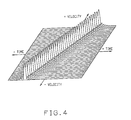
- the ambiguity function of an HFM down sweep signal (as illustrated in FIG. 3) is shown in FIG. 4.
- the time axes for different velocities extend horizontally. They are referred to herein as velocity time axes.
- the velocities for incoming and outgoing targets are indicated by the minus and plus signs, respectively.
- the velocity axis is perpendicular to the time axes.
- Waveforms of a composite nature have been proposed. These usually contain successive up and down sweeps. When an upsweep is followed by a down sweep, the signal is referred to as a "rooftop” signal. Where a down sweep is followed by an upsweep, the signal is referred to as a "vee” signal.
- a rooftop HFM signal is shown in FIG. 5 of the accompanying drawings and the ambiguity function thereof is shown in FIG. 6. As shown in FIG. 6, the ambiguity function is characterized by ridge lines within the velocity-time plane of the ambiguity function, which ridge lines are of different slope. While the use of HFM signals is presently preferred, the unwanted signal suppression features of the present invention are applicable wherever large time bandwidth composite signals having Doppler invariant-like characteristics are used.
- Doppler-invariant is being used throughout this specification to denote a preferred signal waveform (perhaps, best represented by HFM or Hyperbolic Frequency Modulated signals), other related signal forms may be used as long as the correlation loss encountered with Doppler shifted returns is found acceptable.
- One such signal could be, for example, Linear Frequency Modulated (LFM) signals.
- LFM Linear Frequency Modulated
- Any signal may be considered Doppler-invariant as long as the correlation loss for the greatest Doppler-shifted return to be encountered is considered acceptable to the user.
- the invention affords an improved processor which obtains velocity and range sensitive target detection from such composite Doppler invariant signals having segments of different slope as shown in FIG. 6 (wherein the different slopes are in opposite directions) even though the individual signal segments themselves are Doppler invariant-like.
- This processor utilizes a rooftop or vee composite Doppler invariant-like signal, or a simultaneous composite signal where the sweeps occupy the same time interval, characterized by its possessing velocity measurement sensitivity inspite of the Doppler invariant nature of the individual segments of the signal.
- the signal segments of the composite Doppler invariant signal occur successively during a transmission in the case of the roof top signal shown in FIG. 5.
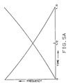
- the signal segments can occur simultaneously during the transmission as shown in FIG. 5A.
- the ambiguity function of such a signal possesses two ridge lines that intersect to form an X pattern having a peak at the crossover point on the zero-velocity time axis. There results a direct relationship between the time separation of the crossed ridge lines and the velocity axis which provides a direct means for the measurement of target velocity. A local time base is introduced, enabling velocity to be obtained from the processing of each composite return. It was found that the Doppler invariant nature of the segments of the composite signal provides a constant amplitude for the ridges, between which the time delay can be measured, thereby yielding a velocity measurement sensitivity that is invariant to velocity magnitude.
- Such time delay measurements may be implemented by a set of tapped delay lines and summers which output a coherent correlation-like detection peak in a bin corresponding to the target velocity.
- the use of one correlator for each segment of the composite signal together with a tapped delay line and a summer network for coherent combination of the outputs from the correlators provides a matched filter much simpler than a conventional matched filter bank, and is a practical and low cost means for the simultaneous high resolution definition of range and velocity for a target in an echo ranging system; the range being determinable by measuring the time delay between the transmission of the signal and the occurrence of the correlation-like detection peak of the target echo in the summer outputs along the time axis.
- Radar and sonar systems are often used in environments where there are a multiplicity of stationary targets, or clutter, that are detrimental to the detection objective at hand. These stationary targets may obscure the targets of interest - those which are moving, like aircraft, missiles, or submarines (i.e., a real target).
- Each of these pairs of crossed ridge lines can exhibit symmetry about the time axis passing through the point of intersection of the pair.
- fixed reverberators which would have ridge lines intersecting on the zero-velocity time axis, would be symmetrical about this axis.
- a target with velocity v presents ridge lines intersecting along the v-velocity time axis and would be symmetrical about that axis.
- the reverberation and the moving target would each have crossed ridge lines whose characteristic intersecting patterns would each exhibit symmetries, but about separate and distinct axes.
- a subtraction process selectively eliminate one pattern while retaining the other(s), such as to cancel, for example, the zero Doppler reverberation while continuing to display the non-zero Doppler targets.
- the subtraction process can, in addition, provide for the subtraction of non-zero velocity unwanted returns; for example, reverberation, such as might occur with Bragg- shifted surface reverberation.
- the subtraction process also can be used to control the "width" of the Doppler-notch by multiple subtractions.
- a selective subtraction process is implemented in accordance with the invention by extracting a replica of the detected output pattern on the velocity-time plane, rotating it 180" about the time axis containing the intersection of a ridge line pair corresponding to an unwanted return, to create a replica of negative amplitude, and adding this rotated (negative) replica back on to the velocity-time plane in proper time alignment, thereby combining the detected output pattern (the output distribution) with the rotated replica to provide an output distribution in which returns from reverberators and false targets are suppressed and from which target velocity and range of actual targets can be derived. Because reverberators are suppressed, the potential for detection of real targets is enhanced.
- the crossed-ridge line pattern to be nulled must exhibit symmetry about the time axis passing through the intersection point, i.e., the ridge line pairs emerging from the velocity-time plane de- sireably must have equal but opposite slopes with respect to the time axis.
- Ridge lines generated by an upsweep and a downsweep HFM transmission having the same starting point and ending point in frequency, with each sweep having the same time duration will not possess, in ambiguity space, perfect symmetry.
- the slopes of each ridge line of a pair of intersecting ridge lines will not be exactly equal and opposite with respect to the time axis, and if not corrected, will yield sub- optimal reverberation suppression.
- the sweep bandwidth and/or the sweep time for one segment of the transmitted composite signal is, in accordance with the invention, altered relative to the sweep bandwidth and/or sweep time of the other segment.
- delays in the distribution of outputs which delays may be interposed after the matched filter processor, can be incrementally adjusted to achieve the desired symmetry.
- the above process can be used with replicas of the output distribution rotated 180 about time axes passing through the intersection points of the ridge lines corresponding to these certain velocities.
- the rotation-subtraction process may be repeated to subtract the non-zero velocity Doppler returns from such targets by shifting the axis of rotation successively to cover the velocity response to be cancelled.
- the multiple rotations may be performed simultaneously.
- a "Doppler notch" of finite bandwidth can be defined to suppress, for example, reverberation whose spectrum is smeared by interaction with moving surface waves.
- the bandwidth of the notch will be determined by the number of rotation (or folding) and subtraction operations.
- FIGS. 1 through 6 as discussed above, illus- rate the building blocks of the presently preferred HFM composite plural segment signal, each segment of which has Doppler invariant characteristics.
- the ambiguity function for the roof-top composite signal is shown. It possesses two ridge lines that intersect to form an "X", having a peak at the cross-over point on the zero-velocity time axis.
- the above-referenced application describes how this composite ambiguity function provides a direct means for the measurement of target velocity in that there is a direct relationship between the velocity axis of the ambiguity function and the time separation of the crossed ridge lines.
- the composite signal introduces a local time base enabling velocity to be derived, and the location of the crossover point enables range to be derived simultaneously with the velocity, and without ambiguity.
- the Doppler invariant nature of each of the segments of the composite signal provides a generally constant amplitude for the ridges, between which the time separations are measured, thereby yielding a velocity measurement sensitively invariant to velocity magnitude.
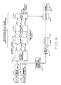
- a matched filter processor of the returns from the target (16, FIG. 9) provides a distribution of outputs from which the velocity and range measurements can be made.
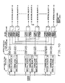
- This processor may be a bank of replica correlators containing a correlator for each velocity to be detected (N correlators), whose individual replicas are a set of N signals having time bases adjusted to match the N velocities to be detected (30, FIG. 10), or the less costly and simpler matched filter bank (32, FIG. 11) as described in the above-referenced application.
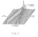
- the distribution of outputs may be displayed on an ambiguity surface as shown in FIGS. 7 and 8 for outgoing and incoming targets, respectively.
- An antenna is used for radar.
- the signal is received at a hydrophone or hydrophone array 14 (an antenna being used for radar), and applied to a receiver 12 where processing for beam forming and the like, as is conventional in sonar or radar, is performed on the signal.
- the composite signal segments can modulate a carrier at microwave frequencies in the radar case or at sonic frequencies in the sonar case.
- the signal may be shifted by conventional heterodying techniques to a convenient frequency for sampling at least at twice the upper frequency limit of the shifted signal to satisfy the Nyquist criteria.
- the signal samples may be digitized and processed in the matched filter processor 16.
- This processor may contain frequency domain or time domain correlators. Such correlators are conventional and may be implemented either in software or in application specific integrated circuits.
- a bank 30 of N correlators for a conventional matched filter processor is shown in greater detail in FIG. 10, and the matched filter processor having only one correlator for each signal segment, as described in the above-referenced application, is shown in FIG. 11.
- a matched filter bank for a roof-top HFM sweep is shown.
- the echo is correlated with replicas of the transmitted signal.
- the replicas may be stored digital replicas which are read out in synchronism with the samples as they are being correlated, all in accordance with well-known correlator or matched filter techniques.
- a half sweep length delay 42 aligns the outputs of the correlators 40 and 42 in time. These outputs are then coherently combined in the delay and summer network 44 to provide an output distribution having the crossed ridge line presentation discussed above.
- the delay lines 1 and 2 time align the correlation outputs for summation, with the correlator outputs propagating in inverse relationship therethrough. Forty-one summer outputs provide forty-one velocity bins in the example illustrated in FIG.11. These delay lines 1 and 2 may be shift registers which should be as wide as the number of bits in each byte of the sampled data which is output from the correlators 38 and 40.
- the clock rate also known as tau step
- tau step which is used is desirably the same as in the correlators 38 and 40 (i.e., at the frequency at least twice the frequency of the carrier on which the Doppler invariant signal is modulated or its frequency shifted version).
- the length is much shorter than the correlation time and is determined solely by the maximum target velocity which is to be measured.
- the delay line lengths may be about 10% of the correlator time delay.
- the delay lines have taps for each bin which corresponds to a velocity bin. These taps are close to each other in delay in accordance with the resolution of the velocity measurement to be achieved. In the illustrated case, there are twenty bins for outgoing targets and twenty for incoming targets, as well as a zero velocity bin.
- the correlators 38 and 40 and the delay line and summer matrices constitute a bank of matched filters, each filter of which is matched to a return from a different target velocity.
- the matched filter outputs go to a slope adjuster 18 (in the event that slope adjustment is not carried out on the transmitted waveform in the transmitter 10).
- the option for slope adjustment in the transmitter 10 is indicated by the legend "SL-ADJ.OPT.”
- the slope adjusters 18 are shown in detail in FIGS. 10 and 11. They operate to make the slopes of the ridge line pairs in the output distribution equal and opposite with respect to the time axis of the distribution, thereby achieving symmetry in ambiguity space to gain maximum suppression of the unwanted returns.
- the slope adjuster 18 provides the adjusted output distribution.
- the slope adjustment requires that velocity outputs on one side of zero velocity be delayed prior to subtracting from the other side of zero velocity, and that those on the other side of zero be advanced before being subtracted from those on the first side of zero velocity. Since time advances are impossible,the first step is to apply a bank of equal, fixed delays to the direct outputs. The effect of these delays is to retard the presentation of a target by their delay time.
- the second set of delays which are specific for each and every velocity output (adjustable delays), accomplish the task of advancing or delaying the signal prior to subtraction for reverberation and false target suppression. If their delay is smaller than the fixed delay, it is an advance. If greater, it is a delay. The two would be equal at zero velocity, if they existed.
- the direct outputs feed the positive side of the subtractors in the reverberation suppressors 20.
- the variable (adjustably) delayed outputs feed the negative side of the subtractors, effecting the reverberation suppression.
- the output distribution from which reverberators and other false targets (unwanted returns) are suppressed, goes to a maximum amplitude detector 22.
- the maximum response is obtained by searching for a maximum amplitude above a given threshold (to exclude much of the background noise and possible ambiguous echoes).
- the output of the detector is a channel number which corresponds the velocity bin and therefore the velocity of the target.
- a transmit waveform correlator 11 will establish a (zero-velocity) time reference for the transmit waveform (rooftop, vee, or other composite Doppler invariant transmission). This time reference will be established by a peak response, such as shown by the zero velocity matched filter waveform illustrated in FIG. 6, defining start of transmission. Then, a delay network 21 inserts a delay to compensate for delays in the system signal processing.
- This delay network interposes a delay after a start pulse from the transmit waveform correlator.
- the delay network 21 outputs a start of clock (SOCL) enable pulse to a clock generator 26.
- SOCL start of clock
- the number of clock pulses which is generated until the time of the maximum or peak amplitude receive signal obtained in the maximum signal amplitude detector 28 is collected in a counter 28.
- the counter counts the clock pulses from the clock 26 until inhibited by the maximum detector output.
- the counter 26 thus stores the return time for the echo to return to the receiver.
- the counter output goes to a range display 38 which may display the range and also, if desired (but not shown), the velocity in terms of the channel number obtained from the maximum detector 28.
- the counter may alternatively be started by applying the transmitter output as an input to the sonar processor 14 and detecting the detection peak.
- a first peak effectively occurs at time zero and the time to the detection peak from the target return (the second peak) is measured by running the counter until inhibited by the later detection peak.
- an optional computational program to symmetrize the slopes of the ridgeline pairs in the output distribution to make the slopes equal and opposite with respect to the time axis, thereby to optimize the subtraction process for cancelling unwanted signals.
- This optional program operates to generate the proper input signal to the transmitter 10 to adjust the relative lengths of the up sweep vs. the down sweep in a composite Doppler-invariant signal.
- the first inputs to the computation provided are the lower and upper frequency limits for the HFM sweep segments (called Sweep Start and Stop Freq. in the drawing), which will remain unchanged during the computation. These frequencies are at the discretion of the user. In the preferred mode, they are the same for the up and down sweeps, but they may differ if desired.
- the second input is the total duration (Duration T) of the up and down sweeps.
- the computer calculates (process 52) the ratio, R, of the up sweep duration, Tu, to the down sweep duration, Td, which will achieve symmetry. This is done using the general expression for an HFM sweep:
- f is the instantaneous frequency
- F o is the start frequency
- k is the constant to execute the sweep in the desired time to the desired stop frequency
- To is an arbitrary start time, generally zero for the up sweep if the signal is to be a roof-top HFM signal as used in the example herein described.
- the newly computed values of k and T for the up and down sweeps are fed to sweep generators 56 and 58 for their use in generating a conventional HFM waveform from a summer 62.
- a delay 60 is inserted to cause the roof top down sweep to begin at the end of the roof top up sweep.
- the slope adjusters 18 in FIGS. 10 and 11 are unnecessary. In the absence of such proper signal conditioning, the slope adjusters are necessary for the optimum suppression of accumulated returns.
- FIG. 13A shows a top view of an ambiguity-like function plotted from the matched filter bank 16 (FIG. 9) output distribution for two returns; one from a false target (a zero velocity reverberator) and another from a target with velocity. Thus, two pairs of x-shaped ridge lines are shown.
- FIG. 13A shows that zero velocity reverberators, whose ridge lines cross at the zero-velocity time axis, possess symmetry about this axis, while the ridge lines from the target with velocity do not possess symmetry about the zero velocity time axis.
- This negative presentation can be removed by electronic clamping of negative signals, as shown in FIG. 13C, to leave the target image standing alone.
- step-wise visualization of the subtraction process is accomplished instantaneously and continuously in the circuit diagrams of FIGS. 10 and 11 by interconnections that are symmetrical about the zero velocity in which the -nth output is subtracted from the + nth output, and the + nth output is subtracted from the -nth output, in a bank of n subtractors to yield a new set of 2n outputs, providing for n incoming and n outgoing target velocities, but with the response for targets or reverberators with zero velocity being suppressed.
- FIG. 14 there is shown a composite simulation of the output distribution of slope- adjusted matched filter outputs for a zero-velocity reverberator displaced to the left of zero time, but like the reverberator shown in FIG. 13A.
- the FIG. 14 distribution is for a typical single-point stationary reverberator.
- FIG. 15 shows the output distribution for a -2knot target occurring at zero relative time.
- FIG. 16 shows the combined output distribution with two pairs of crossed ridge lines for the two returns shown in FIGS. 14 and 15.
- the target echo strength has been reduced by 6dB to emphasize the performance of the reverberation suppression in accordance with the invention.
- the suppressor is nonactive for the case illustrated in FIG. 16. With the suppressor activated, the output distribution illustrated in FIG. 17 is obtained, showing that the reverberator has been essentially eliminated, while the non-zero velocity target is virtually unchanged and can be readily detected by the maximum amplitude detector (22, FIG. 9).
- FIGS. 13-17 the negative image of the echo return in the suppressor's outputs has not been shown. This image is suppressed by zero clamping using clamping circuits 70 as shown in FIG. 11. However, the negative outputs may be used along with the positive outputs, if desired, in a companion pattern recognition process.
- FIG. 18-26 show that the reverberation and false target suppressor can be used to suppress a plurality of selected non-zero velocity false targets and to form a "Doppler notch" of finite bandwidth to suppress, for example, reverberation whose spectrum is smeared, such as example, surface reverberation.
- the process can be implemented sequentially, as it will be described, or preferrably instantaneously, as provided in the schematic diagrams of FIGS. 24 and 25. Sequential suppression involves a plurality of rotations or folding about different velocity time axes. Then storage means must be used ahead of the maximum amplitude detector to retain the outputs resultant from each rotation or fold and subtraction and the maximum amplitude detector is inhibited until all subtraction processes have been completed.
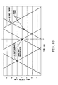
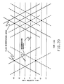
- FIG. 18 shows the plan view of the detector outputs in ambiguity space as function of time and velocity. In this view, only positive excursions can be present (this is the assumed output of a positive polarity detector), and are indicated with solid lines. On successive figures, negative excursions will show as dotted lines. A 2 knot target, which is to be detected, and 1 knot surface and zero knot reverberators, which are to be suppressed, are shown. The reverberators may be thought of as elements of a continuum of reverberators.
- FIG. 19 shows the view with a zero velocity rotation and combination done.
- the zero velocity reverberator has disappeared.
- the positive velocity target and reverberator now appear not only as themselves, but also as a negative versions at equal but opposite negative velocity.
- FIG. 20 shows the view after a second rotation and combination about the 1 knot-velocity time axis.
- the 1 knot reverberator is now cancelled, but a new false reverberator appears at a velocity of 3 knots.
- the 2 knot target appears as itself and as itself duplicated at twice its velocity.
- FIG. 21 shows the pattern of FIG. 19 after this clamp has been applied
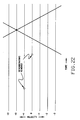
- FIG. 22 shows the view after the successive rotation about the + 1 knot-velocity time axis, and the subsequent combination.
- the + knot reverberator disappears, and the target at + knots remains only as itself, showing successful supres- sion of the reverberators.
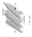
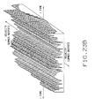
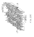
- FIGS. 23A through 23F An example of such continuum processing is shown in FIGS. 23A through 23F which include the representation, by computer simulation, of bottom (zero Doppler) reverberation characterized by a random function of time, convolved with the transmit signal.
- FIGS. 23A and 23B show the time-randomized zero Doppler reverberation, as it might appear in the output distribution of the matched filter bank of the processor of FIG. 11, for, respectively, the HFM upsweep and the HFM downsweep, representing the building blocks of the composite Doppler invariant transmitted signal.
- FIG. 23C shows the combined distribution when the individual segments are connected together as a roof-top HFM transmission. Note that the output distribution (of reverberation) has a random character in both the velocity and time directions.
- FIG. 23D illustrates the output that would occur for a -2 knot target in the absence of any background (noise or reverberation).
- FIG. 23E shows the combination of the target signal with the reverberant background, with the reverberation peaks 6 dB above the target peak return.
- the target's presence cannot be detected with the naked eye.
- FIG. 23F shows the output distribution with the processor of FIG. 10 or 11 invoked to suppress zero-Doppler returns.
- the target return at -2 knots is now clearly visible, and the output distribution with the reverberation continuum suppressed is not significantly different from the distribution of FIG. 17 where the reverberator was a point reverberator.
- the suppression process has been shown to operate equally effectively against point reverberators or a continuum of reverberation, and will work against zero velocity reverberators or for reverberation that has a velocity component.
- Such suppression may be accomplished by multifold subtraction, an example of which is shown hereinafter.
- FIG. 24 shows the processor of FIG. 11 interconnected to provide for three-fold subtraction.
- the slope adjustor networks have been omitted, as if slope adjustment was performed on the transmitted signal.
- the interconnections for taps +18, + 19 , +20 and -18, -19, -20 are shown. Similar interconnections may be implemented for the other velocity bins.
- the objective of the example shown in FIG. 24 is to provide, for each velocity bin, an elimination of its output response for a Doppler band centered about zero Doppler with a width of ⁇ one-half of a bin width.
- the Doppler suppression of the interconnections explicitly shown would be for a bandwidth of ⁇ 1 /2 knot centered about zero velocity, for the + 19 knot bin (and for the -19 knot bin).
- bin 19 will output the peak signal from a crossed-ridgeline detection of a 19 knot target, it will also output a (lower amplitude) ridgeline response from a zero velocity return. The process just discussed eliminates that zero velocity response, as well as response out to ⁇ 1/2 knot.
- the 1/2 knot half-bandwidth emerges from the interpolation of the interconnections shown, i.e., between the delay line taps for bins 19 and -18, and, for -1/2 knot, between the delay line taps for bins 19 and -20.
- the interconnections between the taps for bins 19 and -19 duplicate the interconnections for the single fold of FIG. 11.
- the total bandwidth of the notch in this example is 1 knot.
- the subtraction process proceeds, for example, by collecting the detected outputs feeding bins -18, -19, and -20 in a negative sum adder (e.g., 80) and then directing the output of this adder to the (-) minus terminal of the subtractor whose (+) positive terminal connects to the detected bin 19 output.
- the combined output of the subtractor is the new bin 19 output with response to the ⁇ 1/2 Doppler bin width suppressed.
- the new bin output may also include the provision for zero clamping of negative excursions as set forth in FIG. 11.
- the above description extends, by example, to the construction of a set of 2n-2 new bin outputs which possess each the nulled response to the zero ⁇ 1/2 bin width Doppler band.
- the process above-described can be extended to cover notch widths of arbitrary extent, either centered about zero velocity or some other non-zero velocity.
- FIG. 25 there is shown a processor as shown in FIG. 24, especially suitable for subtracting large reverberators embedded within a noise background.
- a processor as shown in FIG. 24, especially suitable for subtracting large reverberators embedded within a noise background.
- they are peak detected in peak detectors 90 and 92.
- the peak detectors output only the largest of the three outputs, which process effectively acts as a single fold rotation/subtraction operation, effective over a broadened bandwidth on the largest reverberator.
- the outputs to the adders 80 and 82 or the peak detectors 90 and 92 may come from a matched filter embodying a bank of correlators, as shown in FIG. 10, as well as from a dual correlator and summer system of the type described in the above-referenced application and shown in FIG. 11.
- FIG. 26 shows the effective Doppler notch for a nine-fold subtraction process, symmetrically placed with respect to zero velocity, using the peak detector concept of FIG. 25. The same result would be obtained using the negative sum adders of FIG. 24.
- FIG. 26 illustrates the composite response of the detector to unit-amplitude velocity-matched excitation for each velocity bin.
- the total notch width in FIG. 26 is, effectively, four bin widths wide. This comes about, as previously described, since the null velocity for each fold is half way between the output bin being observed and the channel to which the negative peak detector or the negative sum adder is connected for that fold. If each bin in the example corresponded to 1 knot of velocity, the total notch width would cover ⁇ 2 knots centered about zero velocity.
Landscapes
- Engineering & Computer Science (AREA)
- Radar, Positioning & Navigation (AREA)
- Remote Sensing (AREA)
- Physics & Mathematics (AREA)
- Computer Networks & Wireless Communication (AREA)
- General Physics & Mathematics (AREA)
- Acoustics & Sound (AREA)
- Radar Systems Or Details Thereof (AREA)
- Measurement Of Velocity Or Position Using Acoustic Or Ultrasonic Waves (AREA)
Applications Claiming Priority (6)
| Application Number | Priority Date | Filing Date | Title |
|---|---|---|---|
| US67106091A | 1991-03-18 | 1991-03-18 | |
| US671060 | 1991-03-18 | ||
| US70266291A | 1991-05-17 | 1991-05-17 | |
| US702662 | 1991-05-17 | ||
| US71168191A | 1991-06-16 | 1991-06-16 | |
| US711681 | 1991-06-16 |
Publications (2)
| Publication Number | Publication Date |
|---|---|
| EP0504702A2 true EP0504702A2 (de) | 1992-09-23 |
| EP0504702A3 EP0504702A3 (en) | 1993-03-03 |
Family
ID=27418222
Family Applications (1)
| Application Number | Title | Priority Date | Filing Date |
|---|---|---|---|
| EP19920104016 Withdrawn EP0504702A3 (en) | 1991-03-18 | 1992-03-09 | Echo ranging system |
Country Status (5)
| Country | Link |
|---|---|
| EP (1) | EP0504702A3 (de) |
| JP (1) | JPH06201825A (de) |
| AU (2) | AU647346B2 (de) |
| CA (1) | CA2063132A1 (de) |
| IL (1) | IL101077A (de) |
Cited By (7)
| Publication number | Priority date | Publication date | Assignee | Title |
|---|---|---|---|---|
| EP0625715A1 (de) * | 1993-05-21 | 1994-11-23 | STN ATLAS Elektronik GmbH | Verfahren zum Erkennen von Zielen und/oder Bestimmen ihrer Zieldaten |
| FR2754907A1 (fr) * | 1996-10-22 | 1998-04-24 | Thomson Marconi Sonar Sas | Procede de mesure du decalage doppler dans un systeme de detection utilisant des codes ambigus |
| EP0939322A3 (de) * | 1992-12-31 | 1999-10-06 | Rockwell International Corporation | Computerisiertes Radarverfahren zur Messung von Abständen und Relativgeschwindigkeiten zwischen einem Fahrzeug und vor ihm befindlichen Hindernissen |
| GB2394048A (en) * | 2002-10-12 | 2004-04-14 | Westerngeco Seismic Holdings | Seismic cable location using linear period modulated sound |
| EP1500953A1 (de) * | 2003-07-19 | 2005-01-26 | ATLAS ELEKTRONIK GmbH | Verfahren zum Bestimmen von Zieldaten mittels einer Aktiv-Sonaranlage |
| US20130050009A1 (en) * | 2003-10-28 | 2013-02-28 | Preco Electronics, Inc. | Radar echolocater with audio output |
| GB2536487A (en) * | 2015-03-19 | 2016-09-21 | Cambridge Consultants | Coherent method for signalling and ranging using unsynchronized digital radio transceivers |
Families Citing this family (1)
| Publication number | Priority date | Publication date | Assignee | Title |
|---|---|---|---|---|
| JP4828120B2 (ja) * | 2004-12-20 | 2011-11-30 | 古野電気株式会社 | 水中探知装置 |
Family Cites Families (9)
| Publication number | Priority date | Publication date | Assignee | Title |
|---|---|---|---|---|
| US3905033A (en) * | 1968-04-10 | 1975-09-09 | Us Navy | Single composite pulse moving target indicator radar system |
| US3866223A (en) * | 1972-02-01 | 1975-02-11 | Sperry Rand Corp | Multiplicative signal processor for target detection systems with sequential doppler search |
| US4697186A (en) * | 1975-04-30 | 1987-09-29 | The United States Of America As Represented By The Secretary Of The Navy | Velocity discrimination radar |
| US4176351A (en) * | 1978-08-18 | 1979-11-27 | Raytheon Company | Method of operating a continuous wave radar |
| US4388622A (en) * | 1981-04-15 | 1983-06-14 | The United States Of America As Represented By The Secretary Of The Army | Double sideband linear frequency modulation system for radar applications |
| US4566011A (en) * | 1983-07-08 | 1986-01-21 | The United States Of America As Represented By The Secretary Of The Navy | Palindromic polyphase code expander-compressor |
| JPS60169782A (ja) * | 1984-02-14 | 1985-09-03 | Nec Corp | 移動目標表示装置 |
| US4831602A (en) * | 1987-04-02 | 1989-05-16 | Raytheon Company | Simultaneous coherent and incoherent processor for sonar signals |
| US5077702A (en) * | 1990-11-16 | 1991-12-31 | General Electric Company | Doppler consistent hyperbolic frequency modulation |
-
1992
- 1992-02-27 IL IL10107792A patent/IL101077A/en not_active IP Right Cessation
- 1992-03-05 AU AU12140/92A patent/AU647346B2/en not_active Ceased
- 1992-03-09 EP EP19920104016 patent/EP0504702A3/xx not_active Withdrawn
- 1992-03-16 CA CA 2063132 patent/CA2063132A1/en not_active Abandoned
- 1992-03-17 JP JP4091800A patent/JPH06201825A/ja not_active Withdrawn
-
1994
- 1994-06-15 AU AU64750/94A patent/AU664802B2/en not_active Expired - Fee Related
Cited By (13)
| Publication number | Priority date | Publication date | Assignee | Title |
|---|---|---|---|---|
| EP0939322A3 (de) * | 1992-12-31 | 1999-10-06 | Rockwell International Corporation | Computerisiertes Radarverfahren zur Messung von Abständen und Relativgeschwindigkeiten zwischen einem Fahrzeug und vor ihm befindlichen Hindernissen |
| EP0625715A1 (de) * | 1993-05-21 | 1994-11-23 | STN ATLAS Elektronik GmbH | Verfahren zum Erkennen von Zielen und/oder Bestimmen ihrer Zieldaten |
| US5481504A (en) * | 1993-05-21 | 1996-01-02 | Atlas Elektronik Gmbh | Method and device for determining target speed and distance with frequency modulated pulses |
| FR2754907A1 (fr) * | 1996-10-22 | 1998-04-24 | Thomson Marconi Sonar Sas | Procede de mesure du decalage doppler dans un systeme de detection utilisant des codes ambigus |
| WO1998018020A1 (fr) * | 1996-10-22 | 1998-04-30 | Thomson Marconi Sonar S.A.S. | Procede de mesure du decalage doppler dans un systeme de detection utilisant des codes ambigus |
| AU719562B2 (en) * | 1996-10-22 | 2000-05-11 | Thomson Marconi Sonar S.A.S. | Method for measuring the doppler shift in a detection system using ambiguous codes |
| GB2394048A (en) * | 2002-10-12 | 2004-04-14 | Westerngeco Seismic Holdings | Seismic cable location using linear period modulated sound |
| WO2004036253A1 (en) * | 2002-10-12 | 2004-04-29 | Westerngeco Seismic Holdings Limited | Acoustic ranging by application of linear period mudulated sound |
| GB2394048B (en) * | 2002-10-12 | 2006-03-15 | Westerngeco Seismic Holdings | Acoustic ranging by application of linear period modulated sound |
| US8208343B2 (en) | 2002-10-12 | 2012-06-26 | Westerngeco L.L.C. | Acoustic ranging by application of linear period modulated sound |
| EP1500953A1 (de) * | 2003-07-19 | 2005-01-26 | ATLAS ELEKTRONIK GmbH | Verfahren zum Bestimmen von Zieldaten mittels einer Aktiv-Sonaranlage |
| US20130050009A1 (en) * | 2003-10-28 | 2013-02-28 | Preco Electronics, Inc. | Radar echolocater with audio output |
| GB2536487A (en) * | 2015-03-19 | 2016-09-21 | Cambridge Consultants | Coherent method for signalling and ranging using unsynchronized digital radio transceivers |
Also Published As
| Publication number | Publication date |
|---|---|
| AU664802B2 (en) | 1995-11-30 |
| JPH06201825A (ja) | 1994-07-22 |
| AU1214092A (en) | 1992-09-24 |
| CA2063132A1 (en) | 1992-09-19 |
| AU6475094A (en) | 1994-08-11 |
| AU647346B2 (en) | 1994-03-17 |
| EP0504702A3 (en) | 1993-03-03 |
| IL101077A (en) | 1995-08-31 |
Similar Documents
| Publication | Publication Date | Title |
|---|---|---|
| US5212490A (en) | Echo ranging system for detecting velocity and range of targets using composite doppler invariant-like transmissions with suppression of false targets | |
| US3882444A (en) | Steerable parametric conversion array | |
| EP0557660A2 (de) | Signalprozessor | |
| US4916452A (en) | Process for range measurement with a pulse radar of high pulse repetition frequency | |
| Leinbach | Wiener spiking deconvolution and minimum-phase wavelets: A tutorial | |
| EP0285325B1 (de) | Sonarsignalverarbeitungsgerät | |
| US3622970A (en) | Method of seismic prospecting | |
| US5949739A (en) | Sonar bearing estimation of extended targets | |
| EP0504702A2 (de) | Echoentfernungsmessersystem | |
| US6624783B1 (en) | Digital array stretch processor employing two delays | |
| US5251186A (en) | Preprocessor and adaptive beamformer for linear-frequency modulation active signals | |
| US4516220A (en) | Pulse deinterleaving signal processor and method | |
| US3808594A (en) | Multiplicative signal processor for target detection systems | |
| GB2202329A (en) | Imaging systems for marine use | |
| US7286443B2 (en) | Fast coherent processing for codes with periodic line spectra | |
| US5077702A (en) | Doppler consistent hyperbolic frequency modulation | |
| CN104765033B (zh) | 利用互相关函数抑制步进频率成像中距离旁瓣的方法 | |
| US3795912A (en) | Spectrum analysis radar system | |
| Ellinthorpe et al. | Theoretical and empirical results on the characterization of undersea acoustic channels | |
| Bell et al. | Diversity waveform signal processing for delay–doppler measurement and imaging | |
| RU2697937C1 (ru) | Гидролокационный способ обнаружения объекта и измерения его параметров | |
| GB2129935A (en) | An adaptive filter | |
| EP0074204A1 (de) | Bestimmung der Ansprechempfindlichkeit einer Vorrichtung | |
| EP1160584B1 (de) | Verfahren zum Bestimmen von Richtung und/ oder Entfernung reflektierender Zielorte | |
| JPH0933661A (ja) | 相関型探知方法及び装置 |
Legal Events
| Date | Code | Title | Description |
|---|---|---|---|
| PUAI | Public reference made under article 153(3) epc to a published international application that has entered the european phase |
Free format text: ORIGINAL CODE: 0009012 |
|
| AK | Designated contracting states |
Kind code of ref document: A2 Designated state(s): AT BE CH DE DK ES FR GB GR IT LI MC NL PT SE |
|
| PUAL | Search report despatched |
Free format text: ORIGINAL CODE: 0009013 |
|
| AK | Designated contracting states |
Kind code of ref document: A3 Designated state(s): AT BE CH DE DK ES FR GB GR IT LI MC NL PT SE |
|
| 17P | Request for examination filed |
Effective date: 19930902 |
|
| 17Q | First examination report despatched |
Effective date: 19950704 |
|
| STAA | Information on the status of an ep patent application or granted ep patent |
Free format text: STATUS: THE APPLICATION IS DEEMED TO BE WITHDRAWN |
|
| 18D | Application deemed to be withdrawn |
Effective date: 19960619 |