EP0506607A2 - Dispositif de serrage pour joindre deux profilés de façon détachable - Google Patents
Dispositif de serrage pour joindre deux profilés de façon détachable Download PDFInfo
- Publication number
- EP0506607A2 EP0506607A2 EP92810123A EP92810123A EP0506607A2 EP 0506607 A2 EP0506607 A2 EP 0506607A2 EP 92810123 A EP92810123 A EP 92810123A EP 92810123 A EP92810123 A EP 92810123A EP 0506607 A2 EP0506607 A2 EP 0506607A2
- Authority
- EP
- European Patent Office
- Prior art keywords
- bolt
- insert core
- profile
- pieces
- holding pieces
- Prior art date
- Legal status (The legal status is an assumption and is not a legal conclusion. Google has not performed a legal analysis and makes no representation as to the accuracy of the status listed.)
- Granted
Links
Images


Classifications
-
- F—MECHANICAL ENGINEERING; LIGHTING; HEATING; WEAPONS; BLASTING
- F16—ENGINEERING ELEMENTS AND UNITS; GENERAL MEASURES FOR PRODUCING AND MAINTAINING EFFECTIVE FUNCTIONING OF MACHINES OR INSTALLATIONS; THERMAL INSULATION IN GENERAL
- F16B—DEVICES FOR FASTENING OR SECURING CONSTRUCTIONAL ELEMENTS OR MACHINE PARTS TOGETHER, e.g. NAILS, BOLTS, CIRCLIPS, CLAMPS, CLIPS OR WEDGES; JOINTS OR JOINTING
- F16B2/00—Friction-grip releasable fastenings
- F16B2/02—Clamps, i.e. with gripping action effected by positive means other than the inherent resistance to deformation of the material of the fastening
-
- F—MECHANICAL ENGINEERING; LIGHTING; HEATING; WEAPONS; BLASTING
- F16—ENGINEERING ELEMENTS AND UNITS; GENERAL MEASURES FOR PRODUCING AND MAINTAINING EFFECTIVE FUNCTIONING OF MACHINES OR INSTALLATIONS; THERMAL INSULATION IN GENERAL
- F16B—DEVICES FOR FASTENING OR SECURING CONSTRUCTIONAL ELEMENTS OR MACHINE PARTS TOGETHER, e.g. NAILS, BOLTS, CIRCLIPS, CLAMPS, CLIPS OR WEDGES; JOINTS OR JOINTING
- F16B7/00—Connections of rods or tubes, e.g. of non-circular section, mutually, including resilient connections
- F16B7/22—Connections of rods or tubes, e.g. of non-circular section, mutually, including resilient connections using hooks or like elements
-
- F—MECHANICAL ENGINEERING; LIGHTING; HEATING; WEAPONS; BLASTING
- F16—ENGINEERING ELEMENTS AND UNITS; GENERAL MEASURES FOR PRODUCING AND MAINTAINING EFFECTIVE FUNCTIONING OF MACHINES OR INSTALLATIONS; THERMAL INSULATION IN GENERAL
- F16B—DEVICES FOR FASTENING OR SECURING CONSTRUCTIONAL ELEMENTS OR MACHINE PARTS TOGETHER, e.g. NAILS, BOLTS, CIRCLIPS, CLAMPS, CLIPS OR WEDGES; JOINTS OR JOINTING
- F16B7/00—Connections of rods or tubes, e.g. of non-circular section, mutually, including resilient connections
- F16B7/04—Clamping or clipping connections
- F16B7/044—Clamping or clipping connections for rods or tubes being in angled relationship
- F16B7/0446—Clamping or clipping connections for rods or tubes being in angled relationship for tubes using the innerside thereof
- F16B7/0453—Clamping or clipping connections for rods or tubes being in angled relationship for tubes using the innerside thereof the tubes being drawn towards each other
- F16B7/0466—Clamping or clipping connections for rods or tubes being in angled relationship for tubes using the innerside thereof the tubes being drawn towards each other by a screw-threaded stud with a conical tip acting on an inclined surface
-
- F—MECHANICAL ENGINEERING; LIGHTING; HEATING; WEAPONS; BLASTING
- F16—ENGINEERING ELEMENTS AND UNITS; GENERAL MEASURES FOR PRODUCING AND MAINTAINING EFFECTIVE FUNCTIONING OF MACHINES OR INSTALLATIONS; THERMAL INSULATION IN GENERAL
- F16B—DEVICES FOR FASTENING OR SECURING CONSTRUCTIONAL ELEMENTS OR MACHINE PARTS TOGETHER, e.g. NAILS, BOLTS, CIRCLIPS, CLAMPS, CLIPS OR WEDGES; JOINTS OR JOINTING
- F16B2200/00—Constructional details of connections not covered for in other groups of this subclass
- F16B2200/20—Connections with hook-like parts gripping behind a blind side of an element to be connected
- F16B2200/205—Connections with hook-like parts gripping behind a blind side of an element to be connected the hook being a separate retainer
-
- Y—GENERAL TAGGING OF NEW TECHNOLOGICAL DEVELOPMENTS; GENERAL TAGGING OF CROSS-SECTIONAL TECHNOLOGIES SPANNING OVER SEVERAL SECTIONS OF THE IPC; TECHNICAL SUBJECTS COVERED BY FORMER USPC CROSS-REFERENCE ART COLLECTIONS [XRACs] AND DIGESTS
- Y10—TECHNICAL SUBJECTS COVERED BY FORMER USPC
- Y10T—TECHNICAL SUBJECTS COVERED BY FORMER US CLASSIFICATION
- Y10T403/00—Joints and connections
- Y10T403/46—Rod end to transverse side of member
- Y10T403/4602—Corner joint
Definitions
- the present invention relates to a clamping device for releasably connecting two profile pieces.
- a clamping device which is used to connect frames and / or walls composed of profile pieces.
- a longitudinally displaceable bolt guided in a profile piece is provided, which is T-shaped at its head end in order to engage behind a slot of another profile piece.
- the longitudinal displacement of the bolt is achieved in that the conical tip of the screw cooperates eccentrically with a conical recess in the bolt serving as a tightening surface.
- this clamping device it is known from EP-PS 0123683 to secure the anchor bolt in that it is extended by a rod with an extended end part and that the insert core is provided with spreading fingers and has internally projecting cams in order to close the extended end part reach behind.
- a snap lock can also be realized by an integrally molded sleeve with at least one longitudinal slot in which a pin which is arranged diagonally in the rod is guided.
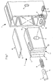
- FIG. 1 shows a first profile piece 1 of a frame composed of a plurality of profile pieces, into which an insert core 2 made of a light material, preferably plastic, can be inserted and locked.
- the insert core 2 is provided with a transverse bore 3 for receiving a fixing bush 4 with a threaded pin 5 and with an invisible longitudinal bore in FIG. 1 for receiving a helical spring 6 and an anchor bolt 7.
- the profile piece 1 preferably has a rectangular cross-section with rails 8 projecting into a cavity for guiding the insert core 2.
- the insert core 2 can be provided with shoulders 9, 9 ', 10, 10', which facilitate the guidance.
- the insert core 2 has on its left end face an opening 11 which extends perpendicular to the axis of the bore 3 and which can optionally be covered by a side plate.
- a side plate 12 In Fig. 1 only such a side plate 12 is shown, which has a central short extension 13 on its left end face.
- the plate 12 and the shoulders 9 and 10 result in two grooves which facilitate the correct insertion of the insert core 2 over the rails 8.
- These side plates are preferably also made of plastic.
- the anchor bolt 7 is slidably mounted in the longitudinal bore, the helical spring or compression spring 6 being accommodated between its one end and the end of the longitudinal bore.
- the anchor bolt 7 there is an approximately conical recess 14 into which the conical end or the tip 15 of the screw 5 projects.
- the screw 5 is guided through the fixing or threaded bushing 4, which in turn can be inserted into the bore 3 of the insert core 2.
- the sleeve 4 has a transverse bore 16 for receiving the anchor bolt 7.
- the conical tip 15 of the screw 5 interacts with the larger conical recess 14 according to the principle of the inclined surfaces and moves the anchor bolt 14 to the right (FIG. 1) in order to close the clamping device.
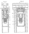
- Fig. 2 also shows a second profile piece 19 with at least one slot in which the ends of the holding pieces 17, 17 'are inserted.
- Such holding pieces 17, 17 ', 18, 18' can for example be held in a rest position with a profile spring 20.
- Fig. 3 for example, two groups of holding pieces of thickness e are shown, namely four holding pieces 17, 17 '... left and 4 holding pieces 18, 18' .... right, the holding pieces 17, 18 'in one Position and the holding pieces 17 ', 18 and the reverse position are stored.
- FIG. 4 shows an embodiment of a holding piece which has a nose 21 in one end region, a bore 22 in the other end region and an extension 23 with an inclined surface 24 in a central region.
- Fig. 5 a variant of the insert core 2 is shown, in which the walls 25, 25 ', which laterally delimit the opening 11, each have a ramp 26, 26', which are provided to be with the inclined surfaces 24 of the holding pieces ( Fig. 4) cooperate to achieve the effect shown in Figures 8 and 9.
- FIG. 6 shows the anchor bolt 7 shown only partially in FIG. 1, which has a cylindrical part in which the conical recess 14 is located and a flattened part which is provided with a bore 27 into which a rod 28 is inserted .
- the rod 28, which is also visible in FIG. 3, serves to support the holding pieces which are provided with the bores 22 (FIG. 4) for this purpose. Such holding pieces can be punched out of light metal or steel, for example.
- the rod 28 can be fixed in the center.
- the profile spring 20 shown in FIG. 7, for example, has at least approximately a trapezoidal cross section.
- the longitudinal edges 30, 30 'at the opening 29 of the profile spring 20 are crimped in order to be able to hold the holding pieces laterally better.
- the bottom of the profile spring 20 has an opening 31 for the anchor bolt 7.
- the spring action of the profile spring 20 allows the holding pieces 17, 17 ', ... 18, 18' ... to be held in such a way that their ends form a type of block, the width of which is somewhat smaller than the width of the slot of the second profile piece 19 , into which they are introduced together, regardless of the orientation of the individual holding pieces with the nose 21 (FIG. 4) alternately to the left or to the right.
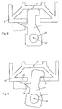
- the holding pieces for example the holding piece 17 'in Fig. 8 are inserted vertically into the slot of the second profile piece 19.
- the distance between the Axis 32 of the bore 22 of the holding piece 17 'or the rod 28 of the anchor bolt 7 (Fig. 6, 3, 1) and a reference point P of the profile piece 19 is equal to Do in this open position.
- the deepest point of the recess 14 of the anchor bolt 7 is in a position offset with respect to the axis of rotation of the screw 5 (FIG. 1) or with respect to the axis of symmetry of the fixing sleeve 4.
- the clamping effect according to the invention can also be achieved with a single holding piece. In practice, however, two or more holding pieces should be used per clamping device. Very good results could be achieved regardless of the order with three holding pieces on the left and right in the anchor bolt 7.
- the ramps 26 can be present directly in the end region (FIG. 2) of the walls at the opening 11 or somewhat further inside (FIG. 5) of the insert core 2.
- the holding pieces 17, 17 ', ... 18, 18', ... could also be clamped laterally between an annular spring and a nut, so that they cannot rotate due to their own weight.
- the spring 20 could thus be omitted.
- the screw 5 with the conical tip 15 and the recess 14 of the anchor bolt 7 form a system of tightening or sliding surfaces, which can also be realized by other means, for example by a dihedral recess 14 in the anchor bolt and one between the sleeve 4 and the Anchor bolt 7 arranged dihedral pawl, such that a screw, preferably without a tip, can press the dihedral pawl against the dihedral recess.
- the profile piece 1 is provided with a bore 3 ', which cooperates with a turn 4' on the threaded bush 4 to hold the insert core 2 in the profile piece 1.
- the profile spring can be a double-acting clamping spring.
- a spring clip is shown in Figures 10 to 13.
- This clamping spring 35 consists, for example, of a base 36 with a preferably round bore 37, two elongated side walls 38, 39 and two narrow side walls 40, 41, which can each be provided with a smaller round bore 42, 42 '.
- Such a clamping spring can act laterally on the narrow sides of all holding pieces and / or on the extreme flat sides of the block formed by the holding pieces.
- the rod 43 may have a taper at each end to hold it in the clamping spring between the bores 42, 42 '.
- the spring 20 (FIG. 7), which is a simplified variant of the spring 35 without narrow side walls, could also have a round bottom hole, the diameter of which is larger than the diameter of the anchor bolt.
- the insert core can be provided in one piece, instead of with glued plates 12, 12 '.
- the insert core can also be constructed similarly to that known from EP-PS 0123683 with regard to the guide grooves and / or the snap holder described therein, wherein a nut that can be screwed onto the corresponding extension of the anchor bolt can also serve as the snap holder.
- the contact surface of the nose 21 has a bevel, preferably at an angle w of approximately 10 degrees.
- w ' 40 degrees.
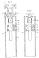
- FIGS. 14 and 15 show the mode of operation of the bush 4 as a safety device blocking the axial movement of the bolt 7.
- This securing effect takes place by itself, since when the screw 5 (FIG. 1) is tightened, the outer edge of the bush 4 engages in the opening 3 'of the profile piece 1 (FIGS. 1 and 14).
- the clamping device is blocked automatically when it clamps, as indicated in FIG. 14 (without screw 5).
- the clamping device is released (Fig. 15) if the screw 5 does not press.
- the bushing 4 can be pressed inwards into the profile 1 in order to be able to pull out the housing without problems.
- the diameter of the bore 16 (FIG.
- the sleeve 4 is approximately a few millimeters larger than the diameter of the bolt 7 in the region of the recess 14, the bore 16 also being oval, but preferably a parallel elongated hole with rounded end edges can to allow a lateral displacement between the bolt 7 and the sleeve 4.
- the pitch of the thread of the screw 5 or the bush 4 can be greater than 1 mm per revolution.
- very good results were achieved with values of 3 and 4.5 mm per revolution.
- a trapezoidal thread for example of the M10 ⁇ 3 type, is preferably used.
- Such a securing system and / or such a pitch of the thread can generally be used in clamping devices of this type.
- the springs 20 in FIGS. 14 and 15 have a very light trapezoidal cutout, which could also be omitted if the housing 2 (Fig. 5) in the lower region of the room where the spring 20 is used, has inwardly tapered surfaces 44, 45, which represent a guide for the bottom of the spring 20.
- This design can be important if, in particular, the elongated side walls of the spring 20 are perpendicular to the bottom 36 (FIG. 12).
- the 14 and 15 has an outer end surface 46, a shoulder surface 47, a front support surface 48 and a rear support surface 49.
- the shoulder surface 47 can be supported against the edge of the wall in the bore 3'.
- the distance between the surfaces 48 and 49 corresponds to the enlarged diameter of the transverse bore 16, which is preferably an elongated hole. The distance between the surfaces 46 and 48 (Fig.
- the distance between the surfaces 47 and 49 is preferably only a little larger than the greatest distance between the inside of the wall 1 'in the region of the bore 3' and the bolt 7 in the region behind the recess 14.
- the versions with trapezoidal thread and / or with holding pieces can also be used without expanding the transverse bore 16.
- the first version is faster because there is less need to turn the trapezoidal thread pin to clamp the device.
Landscapes
- General Engineering & Computer Science (AREA)
- Engineering & Computer Science (AREA)
- Mechanical Engineering (AREA)
- Clamps And Clips (AREA)
- Dowels (AREA)
- Mutual Connection Of Rods And Tubes (AREA)
- Furniture Connections (AREA)
- Joining Of Building Structures In Genera (AREA)
- Moulds For Moulding Plastics Or The Like (AREA)
- Automobile Manufacture Line, Endless Track Vehicle, Trailer (AREA)
- Gripping Jigs, Holding Jigs, And Positioning Jigs (AREA)
- Connection Of Plates (AREA)
- Snaps, Bayonet Connections, Set Pins, And Snap Rings (AREA)
Applications Claiming Priority (4)
| Application Number | Priority Date | Filing Date | Title |
|---|---|---|---|
| CH903/91 | 1991-03-25 | ||
| CH90391 | 1991-03-25 | ||
| CH323491 | 1991-11-06 | ||
| CH3234/91 | 1991-11-06 |
Publications (3)
| Publication Number | Publication Date |
|---|---|
| EP0506607A2 true EP0506607A2 (fr) | 1992-09-30 |
| EP0506607A3 EP0506607A3 (en) | 1993-02-24 |
| EP0506607B1 EP0506607B1 (fr) | 1995-08-02 |
Family
ID=25686065
Family Applications (1)
| Application Number | Title | Priority Date | Filing Date |
|---|---|---|---|
| EP92810123A Expired - Lifetime EP0506607B1 (fr) | 1991-03-25 | 1992-02-20 | Dispositif de serrage pour joindre deux profilés de façon détachable |
Country Status (27)
| Country | Link |
|---|---|
| US (1) | US5209598A (fr) |
| EP (1) | EP0506607B1 (fr) |
| JP (1) | JP3212671B2 (fr) |
| KR (1) | KR100221809B1 (fr) |
| CN (1) | CN1030476C (fr) |
| AR (1) | AR248056A1 (fr) |
| AT (1) | ATE125907T1 (fr) |
| AU (1) | AU646321B2 (fr) |
| BG (1) | BG60881B1 (fr) |
| BR (1) | BR9200952A (fr) |
| CA (1) | CA2061722C (fr) |
| CZ (1) | CZ280417B6 (fr) |
| DE (1) | DE59203071D1 (fr) |
| DK (1) | DK0506607T3 (fr) |
| ES (1) | ES2078014T3 (fr) |
| FI (1) | FI100480B (fr) |
| GR (1) | GR3017231T3 (fr) |
| HK (1) | HK159596A (fr) |
| HR (1) | HRP940782B1 (fr) |
| HU (1) | HU211114B (fr) |
| MX (1) | MX9201214A (fr) |
| NZ (1) | NZ241599A (fr) |
| RU (1) | RU2089759C1 (fr) |
| SI (1) | SI9210194B (fr) |
| SK (1) | SK278525B6 (fr) |
| TR (1) | TR25765A (fr) |
| YU (1) | YU48212B (fr) |
Cited By (3)
| Publication number | Priority date | Publication date | Assignee | Title |
|---|---|---|---|---|
| US6116808A (en) * | 1995-11-28 | 2000-09-12 | Syma Intercontinental Ag | Clamping device for detachably connecting two profiled parts |
| WO2010057324A1 (fr) * | 2008-11-21 | 2010-05-27 | Syma Intercontinental Ag | Dispositif pour l'assemblage de deux pièces profilées |
| WO2012038376A1 (fr) | 2010-09-23 | 2012-03-29 | Syma Intercontinental Ag | Plaque coulissante pour fermeture à excentrique |
Families Citing this family (29)
| Publication number | Priority date | Publication date | Assignee | Title |
|---|---|---|---|---|
| DE4218842A1 (de) * | 1992-06-09 | 1993-12-16 | Offenbroich A | Klemmvorrichtung |
| DE9218816U1 (de) * | 1992-10-26 | 1995-08-24 | Grass AG, Höchst, Vorarlberg | Trennwand zur Schubladeneinteilung von Schubladen |
| SE501953C2 (sv) * | 1994-07-04 | 1995-06-26 | Foga System International Ab | Anordning vid koppling |
| US5560476A (en) * | 1995-03-06 | 1996-10-01 | Lee; Ming-Deh | Name card case |
| US5657604A (en) * | 1995-11-27 | 1997-08-19 | Downing Displays, Inc. | Panel connector |
| EP1003977B1 (fr) * | 1997-08-12 | 2003-06-25 | Syma Intercontinental Ag | Douille de fermeture pour un dispositif de serrage utilise pour assembler de facon liberable deux pieces profilees |
| DE19855928A1 (de) * | 1998-12-04 | 2000-06-08 | Wolfgang Rixen | Verbindung zweier Profilstäbe |
| EP1061272B1 (fr) * | 1999-06-17 | 2003-03-19 | Zihlmann Engineering | Liaison transversale pour des barres profilées |
| ITBO20010528A1 (it) * | 2001-09-03 | 2003-03-03 | Work Corp Inc S R L | Sistema di fissaggio per strutture modulari d'arredamento |
| JP5111058B2 (ja) * | 2007-11-02 | 2012-12-26 | Sus株式会社 | 構造材の結合構造 |
| US8333529B2 (en) * | 2008-02-15 | 2012-12-18 | Telezygology, Inc. | Strip fastener |
| BR112012008989B1 (pt) * | 2009-10-14 | 2021-08-31 | Donaldson Company, Inc | Cartuchos de filtro de ar e gaxeta para uso com um cartucho de filtro |
| EP2564074B1 (fr) * | 2010-04-26 | 2020-09-09 | Blanking Systems, Inc. | Pièce d'angle pour interconnexion mécanique d'éléments de châssis |
| CN102487030B (zh) * | 2010-12-06 | 2013-12-18 | 上海微电子装备有限公司 | 双工件台夹持机构 |
| CN102535802B (zh) * | 2011-12-22 | 2014-11-26 | 苏州金螳螂建筑装饰股份有限公司 | 木质装饰面板单元化生产、快速安装的结构系统 |
| CN102535808A (zh) * | 2011-12-22 | 2012-07-04 | 苏州金螳螂建筑装饰股份有限公司 | 装饰面板快速安装锁紧装置 |
| CN102797732B (zh) * | 2012-08-04 | 2014-04-09 | 伍洲 | 可拆装的连接装置 |
| US8747013B2 (en) * | 2012-09-21 | 2014-06-10 | Davis Aircraft Products Co., Inc. | Fastening devices |
| USD731678S1 (en) * | 2013-11-21 | 2015-06-09 | Lite Guard Safety Solutions Pty Ltd. | Lifting lug |
| CN104709841B (zh) * | 2013-12-13 | 2019-11-12 | 福特全球技术公司 | 可伸展的千斤顶工具及使用该工具的千斤顶总成 |
| DE102014101158B4 (de) | 2014-01-30 | 2026-03-26 | Lamello Ag | Verbindungsmittel und Verfahren zum Verbinden zweier Bauteile |
| US10378570B2 (en) | 2015-01-07 | 2019-08-13 | Fyrn | Securing pin for securing structural members |
| ITUB20153670A1 (it) * | 2015-09-16 | 2017-03-16 | Leonardo Srl | Dispositivo di giunzione nascosto per parti di mobili e articoli da arredamento |
| CN105345754B (zh) * | 2015-11-23 | 2017-05-03 | 唐山市长智农工具设计制造有限公司 | 速配型手工具柄裤连接结构及其安装方法 |
| CN105545907B (zh) * | 2016-02-29 | 2017-07-04 | 南通铁人运动用品有限公司 | 一种转臂拉销 |
| CN105674023A (zh) * | 2016-04-13 | 2016-06-15 | 叶绍靖 | 一种增强稳定性的弹性紧固装置 |
| CN107387524A (zh) * | 2017-08-17 | 2017-11-24 | 中山市荣创家具五金制品有限公司 | 连接组件及桌体主架 |
| US12286990B2 (en) * | 2020-09-01 | 2025-04-29 | E. Leet Woodworking, Llc | Fastener system for furniture |
| US20240188712A1 (en) * | 2020-09-01 | 2024-06-13 | E. Leet Woodworking, Llc | Fastener system for slatted construction |
Family Cites Families (10)
| Publication number | Priority date | Publication date | Assignee | Title |
|---|---|---|---|---|
| CH555007A (de) * | 1971-09-10 | 1974-10-15 | Swoboda Hellmuth | Vorrichtung zum loesbaren verbinden eines elementes mit einem eine hinterschneidung aufweisenden profil. |
| CH576591A5 (fr) * | 1974-04-09 | 1976-06-15 | Syma Intercontinental Sa | |
| DE2623814A1 (de) * | 1976-05-28 | 1977-12-08 | Albrecht Streib | Loesbare verbindung zweier teile eines gestells |
| SE417859B (sv) * | 1978-02-02 | 1981-04-13 | Thure Svensson | Kopplingsorgan |
| CH632064A5 (en) * | 1978-04-03 | 1982-09-15 | Syma Intercontinental Sa | Clamping device for the detachable connection of two profiled pieces |
| CH657109A5 (de) * | 1982-07-30 | 1986-08-15 | Fehlbaum & Co | Traggestell. |
| CH657190A5 (de) * | 1982-11-01 | 1986-08-15 | Syma Intercontinental Sa | Klemmvorrichtung zum loesbaren verbinden zweier profilstuecke. |
| ATE30620T1 (de) * | 1984-07-02 | 1987-11-15 | Vieler Gmbh Geb | Verbinder zum kuppeln von profilstangen eines gestells. |
| DE3821625A1 (de) * | 1988-06-27 | 1989-12-28 | Kluge Dr Heinz Nachf | Spannverschluss |
| SE465279B (sv) * | 1989-03-08 | 1991-08-19 | Foga System Ab | Kopplingsanordning foer loesbar hopfogning av tvaa byggelement |
-
1992
- 1992-01-31 RU SU925011187A patent/RU2089759C1/ru active
- 1992-02-12 NZ NZ241599A patent/NZ241599A/xx not_active IP Right Cessation
- 1992-02-13 AU AU10956/92A patent/AU646321B2/en not_active Ceased
- 1992-02-18 US US07/835,842 patent/US5209598A/en not_active Expired - Lifetime
- 1992-02-20 DE DE59203071T patent/DE59203071D1/de not_active Expired - Lifetime
- 1992-02-20 DK DK92810123.7T patent/DK0506607T3/da not_active Application Discontinuation
- 1992-02-20 ES ES92810123T patent/ES2078014T3/es not_active Expired - Lifetime
- 1992-02-20 AT AT92810123T patent/ATE125907T1/de not_active IP Right Cessation
- 1992-02-20 EP EP92810123A patent/EP0506607B1/fr not_active Expired - Lifetime
- 1992-02-24 CA CA002061722A patent/CA2061722C/fr not_active Expired - Fee Related
- 1992-02-24 TR TR92/0157A patent/TR25765A/xx unknown
- 1992-02-25 YU YU19492A patent/YU48212B/sh unknown
- 1992-02-25 SI SI9210194A patent/SI9210194B/sl not_active IP Right Cessation
- 1992-03-06 AR AR92321890A patent/AR248056A1/es active
- 1992-03-11 JP JP05267892A patent/JP3212671B2/ja not_active Expired - Lifetime
- 1992-03-19 BR BR929200952A patent/BR9200952A/pt not_active IP Right Cessation
- 1992-03-19 MX MX9201214A patent/MX9201214A/es not_active IP Right Cessation
- 1992-03-24 HU HU9200978A patent/HU211114B/hu not_active IP Right Cessation
- 1992-03-24 BG BG96128A patent/BG60881B1/bg unknown
- 1992-03-24 FI FI921260A patent/FI100480B/fi active IP Right Grant
- 1992-03-25 KR KR1019920004813A patent/KR100221809B1/ko not_active Expired - Fee Related
- 1992-03-25 CN CN92101969A patent/CN1030476C/zh not_active Expired - Fee Related
- 1992-03-25 SK SK894-92A patent/SK278525B6/sk not_active IP Right Cessation
- 1992-03-25 CZ CS92894A patent/CZ280417B6/cs not_active IP Right Cessation
-
1994
- 1994-10-26 HR HR940782A patent/HRP940782B1/xx not_active IP Right Cessation
-
1995
- 1995-08-30 GR GR950402339T patent/GR3017231T3/el unknown
-
1996
- 1996-08-22 HK HK159596A patent/HK159596A/xx not_active IP Right Cessation
Cited By (8)
| Publication number | Priority date | Publication date | Assignee | Title |
|---|---|---|---|---|
| US6116808A (en) * | 1995-11-28 | 2000-09-12 | Syma Intercontinental Ag | Clamping device for detachably connecting two profiled parts |
| WO2010057324A1 (fr) * | 2008-11-21 | 2010-05-27 | Syma Intercontinental Ag | Dispositif pour l'assemblage de deux pièces profilées |
| WO2012038376A1 (fr) | 2010-09-23 | 2012-03-29 | Syma Intercontinental Ag | Plaque coulissante pour fermeture à excentrique |
| CN103119308A (zh) * | 2010-09-23 | 2013-05-22 | 西马洲际股份有限公司 | 用于偏心锁的滑板 |
| CN103119308B (zh) * | 2010-09-23 | 2014-12-17 | 西马洲际股份有限公司 | 用于偏心锁的滑板 |
| AU2011304534B2 (en) * | 2010-09-23 | 2015-04-30 | Syma Intercontinental Ag | Slide plate for a cam-type closure |
| US9051948B2 (en) | 2010-09-23 | 2015-06-09 | Syma Intercontinental Ag | Slide plate for an eccentric closure |
| EA025343B1 (ru) * | 2010-09-23 | 2016-12-30 | Сима Интерконтиненталь АГ | Зажимное устройство с кулачковым замком и скользящей пластиной |
Also Published As
Similar Documents
| Publication | Publication Date | Title |
|---|---|---|
| EP0506607B1 (fr) | Dispositif de serrage pour joindre deux profilés de façon détachable | |
| DE69010650T2 (de) | Vorrichtung zum geraderichten, befestigen, zusammendrücken und ausdehnen der wirbelsäule. | |
| DE3687293T2 (de) | Vollstaendig gegliederte lagerungsvorrichtung. | |
| DE69318556T2 (de) | Klemmbacke | |
| DE2612030A1 (de) | Verstelleinrichtung zur laengenverstellung eines gurtes oder dergleichen | |
| EP0370172B1 (fr) | Dispositif de réglage en hauteur échelonné pour ferrure de fixation ou de renvoi d'une ceinture de sécurité ou équivalent | |
| DE2732423A1 (de) | Formvorrichtung | |
| DE2847006B1 (de) | AEussere Spannvorrichtung fuer chirurgische Zwecke | |
| DE69304821T2 (de) | Anordnung in einem Lastträger | |
| EP0415394A2 (fr) | Joint d'angle pour chassis de porte ou de fenêtre | |
| DE4135674C1 (fr) | ||
| DE2164093A1 (de) | Schneidwerkzeug | |
| DE8712171U1 (de) | Positioniervorrichtung sowie damit versehener Gleitklotz und Spannanker zum Festlegen von Werkstücken an einer Werkzeugmaschine | |
| DE1755529C3 (de) | Verbindungsglied für Reifenketten | |
| DE4110185C1 (fr) | ||
| DE3009076C2 (fr) | ||
| EP1199435A2 (fr) | Bouchon d'extrémité pour la fixation par vissage des croisillons au cadre espaceur, en particulier de vitrages isolants | |
| EP0616135A2 (fr) | Dispositif de raccordement pour éléments profilés | |
| EP0357735A1 (fr) | Paroi a elements allonges. | |
| DE69305423T2 (de) | Verkehrszeichen | |
| EP0240784B1 (fr) | Connecteur pour tuyaux ou profils tubulaires | |
| AT397218B (de) | Zwickbacken | |
| AT395114B (de) | Fuer skibindungen bestimmter backen | |
| DE1302838B (fr) | ||
| DE29612564U1 (de) | Klemmvorrichtung zum lösbaren Verbinden zweier Profilstücke |
Legal Events
| Date | Code | Title | Description |
|---|---|---|---|
| PUAI | Public reference made under article 153(3) epc to a published international application that has entered the european phase |
Free format text: ORIGINAL CODE: 0009012 |
|
| AK | Designated contracting states |
Kind code of ref document: A2 Designated state(s): AT BE CH DE DK ES FR GB GR IT LI LU NL PT SE |
|
| 17P | Request for examination filed |
Effective date: 19921009 |
|
| PUAL | Search report despatched |
Free format text: ORIGINAL CODE: 0009013 |
|
| AK | Designated contracting states |
Kind code of ref document: A3 Designated state(s): AT BE CH DE DK ES FR GB GR IT LI LU NL PT SE |
|
| 17Q | First examination report despatched |
Effective date: 19940209 |
|
| GRAA | (expected) grant |
Free format text: ORIGINAL CODE: 0009210 |
|
| AK | Designated contracting states |
Kind code of ref document: B1 Designated state(s): AT BE CH DE DK ES FR GB GR IT LI LU NL PT SE |
|
| ITF | It: translation for a ep patent filed | ||
| REF | Corresponds to: |
Ref document number: 125907 Country of ref document: AT Date of ref document: 19950815 Kind code of ref document: T |
|
| REF | Corresponds to: |
Ref document number: 59203071 Country of ref document: DE Date of ref document: 19950907 |
|
| GBT | Gb: translation of ep patent filed (gb section 77(6)(a)/1977) |
Effective date: 19950812 |
|
| REG | Reference to a national code |
Ref country code: DK Ref legal event code: T3 |
|
| REG | Reference to a national code |
Ref country code: GR Ref legal event code: FG4A Free format text: 3017231 |
|
| ET | Fr: translation filed | ||
| REG | Reference to a national code |
Ref country code: ES Ref legal event code: FG2A Ref document number: 2078014 Country of ref document: ES Kind code of ref document: T3 |
|
| PLBE | No opposition filed within time limit |
Free format text: ORIGINAL CODE: 0009261 |
|
| 26N | No opposition filed | ||
| REG | Reference to a national code |
Ref country code: GB Ref legal event code: IF02 |
|
| REG | Reference to a national code |
Ref country code: CH Ref legal event code: PCAR Free format text: ISLER & PEDRAZZINI AG;POSTFACH 1772;8027 ZUERICH (CH) |
|
| PGFP | Annual fee paid to national office [announced via postgrant information from national office to epo] |
Ref country code: LU Payment date: 20090216 Year of fee payment: 18 Ref country code: ES Payment date: 20090220 Year of fee payment: 18 Ref country code: DK Payment date: 20090213 Year of fee payment: 18 |
|
| PGFP | Annual fee paid to national office [announced via postgrant information from national office to epo] |
Ref country code: PT Payment date: 20090204 Year of fee payment: 18 Ref country code: NL Payment date: 20090217 Year of fee payment: 18 |
|
| PGFP | Annual fee paid to national office [announced via postgrant information from national office to epo] |
Ref country code: GR Payment date: 20090226 Year of fee payment: 18 Ref country code: GB Payment date: 20090219 Year of fee payment: 18 |
|
| PGFP | Annual fee paid to national office [announced via postgrant information from national office to epo] |
Ref country code: SE Payment date: 20090216 Year of fee payment: 18 Ref country code: IT Payment date: 20090226 Year of fee payment: 18 |
|
| PGFP | Annual fee paid to national office [announced via postgrant information from national office to epo] |
Ref country code: BE Payment date: 20090408 Year of fee payment: 18 |
|
| PGFP | Annual fee paid to national office [announced via postgrant information from national office to epo] |
Ref country code: FR Payment date: 20090213 Year of fee payment: 18 |
|
| PGFP | Annual fee paid to national office [announced via postgrant information from national office to epo] |
Ref country code: CH Payment date: 20091217 Year of fee payment: 19 |
|
| PGFP | Annual fee paid to national office [announced via postgrant information from national office to epo] |
Ref country code: DE Payment date: 20100219 Year of fee payment: 19 Ref country code: AT Payment date: 20100212 Year of fee payment: 19 |
|
| REG | Reference to a national code |
Ref country code: PT Ref legal event code: MM4A Free format text: LAPSE DUE TO NON-PAYMENT OF FEES Effective date: 20100820 |
|
| BERE | Be: lapsed |
Owner name: *SYMA INTERCONTINENTAL A.G. Effective date: 20100228 |
|
| REG | Reference to a national code |
Ref country code: NL Ref legal event code: V1 Effective date: 20100901 |
|
| REG | Reference to a national code |
Ref country code: DK Ref legal event code: EBP |
|
| EUG | Se: european patent has lapsed | ||
| GBPC | Gb: european patent ceased through non-payment of renewal fee |
Effective date: 20100220 |
|
| REG | Reference to a national code |
Ref country code: FR Ref legal event code: ST Effective date: 20101029 |
|
| PG25 | Lapsed in a contracting state [announced via postgrant information from national office to epo] |
Ref country code: PT Free format text: LAPSE BECAUSE OF NON-PAYMENT OF DUE FEES Effective date: 20100820 Ref country code: NL Free format text: LAPSE BECAUSE OF NON-PAYMENT OF DUE FEES Effective date: 20100901 Ref country code: FR Free format text: LAPSE BECAUSE OF NON-PAYMENT OF DUE FEES Effective date: 20100301 Ref country code: DK Free format text: LAPSE BECAUSE OF NON-PAYMENT OF DUE FEES Effective date: 20100228 |
|
| PG25 | Lapsed in a contracting state [announced via postgrant information from national office to epo] |
Ref country code: BE Free format text: LAPSE BECAUSE OF NON-PAYMENT OF DUE FEES Effective date: 20100228 |
|
| REG | Reference to a national code |
Ref country code: ES Ref legal event code: FD2A Effective date: 20110309 |
|
| PG25 | Lapsed in a contracting state [announced via postgrant information from national office to epo] |
Ref country code: GB Free format text: LAPSE BECAUSE OF NON-PAYMENT OF DUE FEES Effective date: 20100220 Ref country code: IT Free format text: LAPSE BECAUSE OF NON-PAYMENT OF DUE FEES Effective date: 20100220 |
|
| PG25 | Lapsed in a contracting state [announced via postgrant information from national office to epo] |
Ref country code: ES Free format text: LAPSE BECAUSE OF NON-PAYMENT OF DUE FEES Effective date: 20110308 |
|
| PG25 | Lapsed in a contracting state [announced via postgrant information from national office to epo] |
Ref country code: ES Free format text: LAPSE BECAUSE OF NON-PAYMENT OF DUE FEES Effective date: 20100221 |
|
| REG | Reference to a national code |
Ref country code: CH Ref legal event code: PL |
|
| PG25 | Lapsed in a contracting state [announced via postgrant information from national office to epo] |
Ref country code: LI Free format text: LAPSE BECAUSE OF NON-PAYMENT OF DUE FEES Effective date: 20110228 Ref country code: CH Free format text: LAPSE BECAUSE OF NON-PAYMENT OF DUE FEES Effective date: 20110228 |
|
| PG25 | Lapsed in a contracting state [announced via postgrant information from national office to epo] |
Ref country code: AT Free format text: LAPSE BECAUSE OF NON-PAYMENT OF DUE FEES Effective date: 20110220 |
|
| REG | Reference to a national code |
Ref country code: DE Ref legal event code: R119 Ref document number: 59203071 Country of ref document: DE Effective date: 20110901 |
|
| PG25 | Lapsed in a contracting state [announced via postgrant information from national office to epo] |
Ref country code: LU Free format text: LAPSE BECAUSE OF NON-PAYMENT OF DUE FEES Effective date: 20100220 Ref country code: SE Free format text: LAPSE BECAUSE OF NON-PAYMENT OF DUE FEES Effective date: 20100221 |
|
| PG25 | Lapsed in a contracting state [announced via postgrant information from national office to epo] |
Ref country code: DE Free format text: LAPSE BECAUSE OF NON-PAYMENT OF DUE FEES Effective date: 20110901 |