EP0240784B1 - Connecteur pour tuyaux ou profils tubulaires - Google Patents
Connecteur pour tuyaux ou profils tubulaires Download PDFInfo
- Publication number
- EP0240784B1 EP0240784B1 EP87103887A EP87103887A EP0240784B1 EP 0240784 B1 EP0240784 B1 EP 0240784B1 EP 87103887 A EP87103887 A EP 87103887A EP 87103887 A EP87103887 A EP 87103887A EP 0240784 B1 EP0240784 B1 EP 0240784B1
- Authority
- EP
- European Patent Office
- Prior art keywords
- connector according
- connector
- clamping jaw
- bar
- limbs
- Prior art date
- Legal status (The legal status is an assumption and is not a legal conclusion. Google has not performed a legal analysis and makes no representation as to the accuracy of the status listed.)
- Expired
Links
- 230000009467 reduction Effects 0.000 claims 4
- QNRATNLHPGXHMA-XZHTYLCXSA-N (r)-(6-ethoxyquinolin-4-yl)-[(2s,4s,5r)-5-ethyl-1-azabicyclo[2.2.2]octan-2-yl]methanol;hydrochloride Chemical compound Cl.C([C@H]([C@H](C1)CC)C2)CN1[C@@H]2[C@H](O)C1=CC=NC2=CC=C(OCC)C=C21 QNRATNLHPGXHMA-XZHTYLCXSA-N 0.000 claims 1
- 244000089486 Phragmites australis subsp australis Species 0.000 description 6
- 238000004519 manufacturing process Methods 0.000 description 4
- 239000004033 plastic Substances 0.000 description 3
- 230000007704 transition Effects 0.000 description 2
- 238000011109 contamination Methods 0.000 description 1
- 239000000463 material Substances 0.000 description 1
Images

Classifications
-
- F—MECHANICAL ENGINEERING; LIGHTING; HEATING; WEAPONS; BLASTING
- F16—ENGINEERING ELEMENTS AND UNITS; GENERAL MEASURES FOR PRODUCING AND MAINTAINING EFFECTIVE FUNCTIONING OF MACHINES OR INSTALLATIONS; THERMAL INSULATION IN GENERAL
- F16B—DEVICES FOR FASTENING OR SECURING CONSTRUCTIONAL ELEMENTS OR MACHINE PARTS TOGETHER, e.g. NAILS, BOLTS, CIRCLIPS, CLAMPS, CLIPS OR WEDGES; JOINTS OR JOINTING
- F16B7/00—Connections of rods or tubes, e.g. of non-circular section, mutually, including resilient connections
- F16B7/04—Clamping or clipping connections
- F16B7/0406—Clamping or clipping connections for rods or tubes being coaxial
- F16B7/0413—Clamping or clipping connections for rods or tubes being coaxial for tubes using the innerside thereof
-
- F—MECHANICAL ENGINEERING; LIGHTING; HEATING; WEAPONS; BLASTING
- F16—ENGINEERING ELEMENTS AND UNITS; GENERAL MEASURES FOR PRODUCING AND MAINTAINING EFFECTIVE FUNCTIONING OF MACHINES OR INSTALLATIONS; THERMAL INSULATION IN GENERAL
- F16B—DEVICES FOR FASTENING OR SECURING CONSTRUCTIONAL ELEMENTS OR MACHINE PARTS TOGETHER, e.g. NAILS, BOLTS, CIRCLIPS, CLAMPS, CLIPS OR WEDGES; JOINTS OR JOINTING
- F16B12/00—Jointing of furniture or the like, e.g. hidden from exterior
- F16B12/10—Jointing of furniture or the like, e.g. hidden from exterior using pegs, bolts, tenons, clamps, clips, or the like
- F16B12/28—Jointing of furniture or the like, e.g. hidden from exterior using pegs, bolts, tenons, clamps, clips, or the like for metal furniture parts
- F16B12/32—Jointing of furniture or the like, e.g. hidden from exterior using pegs, bolts, tenons, clamps, clips, or the like for metal furniture parts using clamps, clips, wedges, sliding bolts, or the like
Definitions
- the present invention relates to a connector for pipes or pipe-like profiles according to the preamble of claim 1.
- Such connectors are preferably used to connect pipes for a trade fair stand or a shelf system in shop fitting. Particularly where pipe systems have to be assembled or disassembled within a short time, for example also in sports or sports auxiliary devices, connectors of the generic type are preferably used.
- Such a connector is known for example from DE-OS 34 05 928.
- clamping jaws consisting of a longitudinally divided mandrel are loosely plugged together, the half-shell-shaped clamping jaws each being provided with one half of a ring.
- These half rings form both an end stop for the pipes to be pushed open and also through mounting holes running in the transverse direction of the connector, through which a tool can be guided into the interior of the connector with which the expansion element can be actuated.
- the two insert halves of this connector are each provided with quarter shells which, on the one hand, rest on the clamping jaws and, on the other hand, are supported on the inner wall of the pushed-on pipes.
- These quarter shells are preferably formed from plastic.
- this known connector consists of a large number of individual parts, its manufacture is only possible with a high level of production engineering complexity. This inevitably results in high manufacturing costs, which has a particularly disadvantageous effect on the cost structure of an entire pipe system, since a large number of connectors are used here.
- the present invention is therefore based on the object of designing a connector of the generic type in such a way that it enables a firm and desirably stable connection with the simplest design means and is simple and therefore inexpensive to produce.
- the webs can thus form the lines of a rhombus, the corners of which lie opposite one another in the middle region of the respective clamping jaw and on the other hand each in the region of a molded strip.
- these strips serve as a receptacle or abutment for an expansion element which, for example, consists of a threaded pin fixed in the axial direction in one strip, which is screwed into a threaded bore in the other strip.
- the opposing webs are pressed apart or contracted when the threaded pin is turned.
- there is an opposite movement for the clamping jaws i. H. when the webs are pushed apart, the clamping jaws move towards one another and away from one another when the webs are contracted.
- the webs are provided in their end regions, i.e. in the transition region to the respective clamping jaw and in the transition region to the corresponding strip, with longitudinal constrictions which reduce the section modulus and thus facilitate the movement of the webs.
- Plastic or rubber washers one of which is provided on the outside and protrudes from at least one clamping jaw, which characterize a further advantageous embodiment of the invention, form a stop for the pushed-on pipe ends.
- a possibility of free access to the expansion element is also created, namely when the disks are arranged on a cross-sectional plane with the expansion element.
- the disks should then expediently be dimensioned so large that the distance between two pipe ends is at least as large as the size of a tool, for example a screwdriver, with which the expansion element can be actuated.
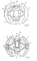
- the connectors shown in Figs. 1 and 2 consist essentially of two opposing cup-shaped jaws 1, the outer surfaces of which are provided with a profile.
- each clamping jaw 1 Starting from the central region of the inside of each clamping jaw 1, two webs 2 are arranged at an angle to one another, the webs 2 of both clamping jaws 1 delimiting an approximately diamond-shaped base area.
- strips 3, 4, 5, 6 are arranged which serve to accommodate expansion elements.
- the expansion element of the connector shown in FIG. 1 is designed as a threaded bolt 7 which is screwed into a threaded bore 8 of the strip 3. With a pin 9, the threaded bolt 7 is rotatably fixed in the opposite bar 4, being secured in the axial direction on the one hand by a shoulder and on the other hand by a rivet head 10.
- the threaded bolt 7 is rotated so that the webs 2 expand or contract in pairs, the connected clamping jaws 1 performing opposite movements, i.e. when the webs 2 are spreading towards one another and at the same Contract moving away from each other.
- the threaded bolt 7 is provided with a left-hand thread, so that the jaws 1 move away from one another when it rotates clockwise.
- the expansion element is formed from a threaded pin 14 which is screwed at one end into a threaded bore in the strip 6 and the other end of which has a blind hole 15 provided with an internal thread.
- a threaded pin 14 which is screwed at one end into a threaded bore in the strip 6 and the other end of which has a blind hole 15 provided with an internal thread.
- an Allen screw 16 is screwed, which is supported with its head on the bottom of a counterbore 17 of the bar 5.
- the hexagon socket screw 16 Since the hexagon socket screw 16 is supported on the bottom of the blind hole 15, when the hexagon socket screw 16 is turned clockwise, the setscrew 14 is also rotated so that the webs 2 move towards one another and thus the clamping jaws move away from one another, so that they are inserted into pipe ends Support on the inner wall and achieve a clamping effect there.
- the grub screw 14, which is provided on its end face facing away from the hexagon socket screw 16 with a tool holder 18, is also turned clockwise, so that the opposite webs 2 spread apart and the clamping jaws 1 move accordingly.
- Each end region of a web 2 is provided with a constriction 13, which reduces the section modulus in this region and thus enables the movements of the webs 2 to be carried out with as little effort as possible.
- the constrictions 13 are alternately provided on the opposite outer surfaces.
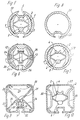
- Fig. 3 it can be seen that one end of tubes 19, 20 are pushed onto the connector, up to a ring 23 forming a stop, which is pushed onto the connector and in its position through the washers 12 is fixed.
- the ring 23 is fixed in that the disks 12 lie in recesses 24 of the ring 23, as can be seen particularly clearly in FIG. 6.
- one of the two pipes 21 shown in FIG. 4 has a longitudinal groove 25.
- a cross section of this tube 21 is shown in FIG. 8.
- FIG 5 shows a cross section through the pipe system including the connector along the line VV in FIG sen, which corresponds approximately to a profile of the inner wall of the tubes 19, 20.
- the ring 23 shown in cross section in FIG. 6 is provided with a slot 26, which allows the head of the threaded bolt 7 on the tool holder side to be freely accessible from the outside, so that a tool can easily be inserted into the tool holder of the threaded bolt 7.
- FIGS. 9 and 10 Further embodiments of the connector are shown in FIGS. 9 and 10.
- the connector is used to connect square tubes 27, which of course can also have a rectangular or any (oval, polygon, etc.) cross section.
- the connector shown in Fig. 9 consists of hook-shaped clamping jaws 28, which are each supported in the corner region of the tube 27 on the inner wall and on which webs 33, 34 are formed, which run towards the center and in strips 31, 32, in which the threaded bolt 7 is received, open.
- the connector is practically made in two parts, the connection of the clamping jaws 28 being effected by the threaded bolt 7.
- the strip 32 overlaps the strip 31 and thus forms a guide for the two connector parts.
- the one shown in FIG. 10 is designed. Only its jaws 30 are matched to the conditions when connecting square tubes. Thus, the clamping jaws 30, as well as the clamping jaws 28 described in the description of the figures for FIG. 9, rest in the corner regions of the inner wall of the square tube 27. The other areas of the square tube 27, however, remain unaffected by the clamping jaws 30 and 28, since otherwise there would be a risk of uneven loading, for example due to contamination within the tube 27.
Landscapes
- Engineering & Computer Science (AREA)
- General Engineering & Computer Science (AREA)
- Mechanical Engineering (AREA)
- Mutual Connection Of Rods And Tubes (AREA)
- Quick-Acting Or Multi-Walled Pipe Joints (AREA)
- Rigid Pipes And Flexible Pipes (AREA)
Claims (21)
Priority Applications (1)
| Application Number | Priority Date | Filing Date | Title |
|---|---|---|---|
| AT87103887T ATE42617T1 (de) | 1986-04-08 | 1987-03-17 | Verbinder fuer rohre oder rohraehnliche profile. |
Applications Claiming Priority (2)
| Application Number | Priority Date | Filing Date | Title |
|---|---|---|---|
| DE19863611741 DE3611741A1 (de) | 1986-04-08 | 1986-04-08 | Verbinder fuer rohre oder rohraehnliche profile |
| DE3611741 | 1986-04-08 |
Publications (2)
| Publication Number | Publication Date |
|---|---|
| EP0240784A1 EP0240784A1 (fr) | 1987-10-14 |
| EP0240784B1 true EP0240784B1 (fr) | 1989-04-26 |
Family
ID=6298202
Family Applications (1)
| Application Number | Title | Priority Date | Filing Date |
|---|---|---|---|
| EP87103887A Expired EP0240784B1 (fr) | 1986-04-08 | 1987-03-17 | Connecteur pour tuyaux ou profils tubulaires |
Country Status (4)
| Country | Link |
|---|---|
| EP (1) | EP0240784B1 (fr) |
| JP (1) | JPH063263Y2 (fr) |
| AT (1) | ATE42617T1 (fr) |
| DE (2) | DE3611741A1 (fr) |
Families Citing this family (3)
| Publication number | Priority date | Publication date | Assignee | Title |
|---|---|---|---|---|
| DE10252673A1 (de) * | 2002-11-11 | 2004-06-17 | Dieter Glockner | Rohr-oder Vollprofilverbinder |
| WO2016004616A1 (fr) * | 2014-07-11 | 2016-01-14 | 嘉华金属(上海)有限公司 | Dispositif de raccord de serrage de tube profilé |
| WO2022250176A1 (fr) * | 2021-05-25 | 2022-12-01 | 이재용 | Dispositif et procédé de fixation d'un composant interne d'un tube de bicyclette |
Family Cites Families (9)
| Publication number | Priority date | Publication date | Assignee | Title |
|---|---|---|---|---|
| DE1829241U (de) * | 1961-01-21 | 1961-04-06 | Linhof Nikolaus Karpf K G Prae | Klemmvorrichtung fuer teleskopartig ausziehbare rohre. |
| GB958706A (en) * | 1962-02-27 | 1964-05-27 | Charles Shoebotham Ltd | Improvements relating to tubular joints and their manufacture |
| DE1983339U (de) * | 1968-01-11 | 1968-04-11 | Illinois Tool Works | Befestigungselement. |
| US3701450A (en) * | 1971-03-24 | 1972-10-31 | Unican Security Systems | Self-holding tube end closures |
| DE2430921A1 (de) * | 1974-06-27 | 1976-01-08 | Metzenauer & Jung Gmbh | Auf einem stab oder dgl. laengsverschiebbare und in beliebiger position festspannbare feststellvorrichtung |
| DE2757040A1 (de) * | 1977-12-21 | 1979-07-05 | Hans Scheuerpflug | Teleskop-anordnung |
| FR2448065A1 (fr) * | 1979-01-30 | 1980-08-29 | Lauzier Rene | Dispositif d'assemblage de tubes de section carree ou rectangulaire formant un angle |
| US4388747A (en) * | 1981-08-10 | 1983-06-21 | Plummer Walter A | One-piece molded toggle clamp |
| DE3405928A1 (de) * | 1984-02-18 | 1985-08-22 | Volker 4300 Essen Rieger | Verbinder fuer die rohre eines rohrmontagesystems |
-
1986
- 1986-04-08 DE DE19863611741 patent/DE3611741A1/de not_active Withdrawn
-
1987
- 1987-03-17 EP EP87103887A patent/EP0240784B1/fr not_active Expired
- 1987-03-17 AT AT87103887T patent/ATE42617T1/de not_active IP Right Cessation
- 1987-03-17 DE DE8787103887T patent/DE3760121D1/de not_active Expired
- 1987-04-07 JP JP1987051681U patent/JPH063263Y2/ja not_active Expired - Lifetime
Also Published As
| Publication number | Publication date |
|---|---|
| DE3611741A1 (de) | 1987-10-15 |
| JPS62163394U (fr) | 1987-10-17 |
| DE3760121D1 (en) | 1989-06-01 |
| ATE42617T1 (de) | 1989-05-15 |
| EP0240784A1 (fr) | 1987-10-14 |
| JPH063263Y2 (ja) | 1994-01-26 |
Similar Documents
| Publication | Publication Date | Title |
|---|---|---|
| DE112012007184B4 (de) | Wellenendadapter und Kugelrollspindelaufbau | |
| DE1290696B (de) | Hohles Bauelement aus elastischem Werkstoff fuer Waende, Decken od. dgl. | |
| WO2000019033A1 (fr) | Cloison de separation | |
| EP0506607A2 (fr) | Dispositif de serrage pour joindre deux profilés de façon détachable | |
| EP0413235A2 (fr) | Noeud d'assemblage | |
| EP0490086B1 (fr) | Raccord à vis pour assembler au moins deux pièces de manière détachable, notamment des barres profilées pourvues de rainures longitudinales | |
| DE69215067T2 (de) | Gliederarmband, insbesondere für Uhren | |
| AT395203B (de) | Verbindungselement fuer den stirnseitigen anschluss eines rohres an ein kugelfoermiges bauteil | |
| DE3115913A1 (de) | Geruest mit stabfoermigen bauelementen | |
| EP0833064A2 (fr) | Assemblage pour des éléments allongés | |
| DE19522224C2 (de) | Bausatz, insbesondere für Busse | |
| DE10343312A1 (de) | Ausfahrbare Mastkonstruktion für einen Hubwagen | |
| EP0870935B1 (fr) | Dispositif d'assemblage pour des éléments allongés | |
| EP0240784A1 (fr) | Connecteur pour tuyaux ou profils tubulaires | |
| EP3828426A1 (fr) | Élément de fixation pour tubes à plusieurs bordures | |
| EP0436795B1 (fr) | Fixation d'une poignée de porte au carré | |
| CH668104A5 (de) | Verbindungsanordnung fuer streben. | |
| WO1987007688A1 (fr) | Systeme de fixation | |
| EP0616135A2 (fr) | Dispositif de raccordement pour éléments profilés | |
| DE10053195C1 (de) | Klemmverbindung | |
| EP1963604A1 (fr) | Pièce coulissante pour ferrure | |
| DE4214520C2 (de) | Zapfenverbindung | |
| AT514628B1 (de) | Griffbeschlag | |
| EP3517793B1 (fr) | Dispositif de raccordement de tuyaux | |
| DE4437106C1 (de) | Vorrichtung zum lösbaren, gelenkigen Verbinden von Strangpreßprofilen, insbesondere für Wandkonstruktionen |
Legal Events
| Date | Code | Title | Description |
|---|---|---|---|
| PUAI | Public reference made under article 153(3) epc to a published international application that has entered the european phase |
Free format text: ORIGINAL CODE: 0009012 |
|
| 17P | Request for examination filed |
Effective date: 19870806 |
|
| AK | Designated contracting states |
Kind code of ref document: A1 Designated state(s): AT BE CH DE FR GB LI LU NL |
|
| 17Q | First examination report despatched |
Effective date: 19880530 |
|
| RAP1 | Party data changed (applicant data changed or rights of an application transferred) |
Owner name: SCHUECO INTERNATIONAL GMBH & CO. |
|
| GRAA | (expected) grant |
Free format text: ORIGINAL CODE: 0009210 |
|
| AK | Designated contracting states |
Kind code of ref document: B1 Designated state(s): AT BE CH DE FR GB LI LU NL |
|
| REF | Corresponds to: |
Ref document number: 42617 Country of ref document: AT Date of ref document: 19890515 Kind code of ref document: T |
|
| GBT | Gb: translation of ep patent filed (gb section 77(6)(a)/1977) | ||
| REF | Corresponds to: |
Ref document number: 3760121 Country of ref document: DE Date of ref document: 19890601 |
|
| ET | Fr: translation filed | ||
| PLBE | No opposition filed within time limit |
Free format text: ORIGINAL CODE: 0009261 |
|
| STAA | Information on the status of an ep patent application or granted ep patent |
Free format text: STATUS: NO OPPOSITION FILED WITHIN TIME LIMIT |
|
| 26N | No opposition filed | ||
| EPTA | Lu: last paid annual fee | ||
| PGFP | Annual fee paid to national office [announced via postgrant information from national office to epo] |
Ref country code: LU Payment date: 19980422 Year of fee payment: 12 |
|
| PG25 | Lapsed in a contracting state [announced via postgrant information from national office to epo] |
Ref country code: LU Free format text: LAPSE BECAUSE OF NON-PAYMENT OF DUE FEES Effective date: 19990317 |
|
| REG | Reference to a national code |
Ref country code: GB Ref legal event code: IF02 |
|
| PGFP | Annual fee paid to national office [announced via postgrant information from national office to epo] |
Ref country code: GB Payment date: 20030224 Year of fee payment: 17 |
|
| PGFP | Annual fee paid to national office [announced via postgrant information from national office to epo] |
Ref country code: NL Payment date: 20030317 Year of fee payment: 17 |
|
| PGFP | Annual fee paid to national office [announced via postgrant information from national office to epo] |
Ref country code: FR Payment date: 20030318 Year of fee payment: 17 |
|
| PGFP | Annual fee paid to national office [announced via postgrant information from national office to epo] |
Ref country code: AT Payment date: 20030321 Year of fee payment: 17 |
|
| PGFP | Annual fee paid to national office [announced via postgrant information from national office to epo] |
Ref country code: CH Payment date: 20030324 Year of fee payment: 17 |
|
| PGFP | Annual fee paid to national office [announced via postgrant information from national office to epo] |
Ref country code: BE Payment date: 20030326 Year of fee payment: 17 |
|
| PG25 | Lapsed in a contracting state [announced via postgrant information from national office to epo] |
Ref country code: GB Free format text: LAPSE BECAUSE OF NON-PAYMENT OF DUE FEES Effective date: 20040317 Ref country code: AT Free format text: LAPSE BECAUSE OF NON-PAYMENT OF DUE FEES Effective date: 20040317 |
|
| PG25 | Lapsed in a contracting state [announced via postgrant information from national office to epo] |
Ref country code: LI Free format text: LAPSE BECAUSE OF NON-PAYMENT OF DUE FEES Effective date: 20040331 Ref country code: CH Free format text: LAPSE BECAUSE OF NON-PAYMENT OF DUE FEES Effective date: 20040331 Ref country code: BE Free format text: LAPSE BECAUSE OF NON-PAYMENT OF DUE FEES Effective date: 20040331 |
|
| BERE | Be: lapsed |
Owner name: *SCHUCO INTERNATIONAL G.M.B.H. & CO. Effective date: 20040331 |
|
| PG25 | Lapsed in a contracting state [announced via postgrant information from national office to epo] |
Ref country code: NL Free format text: LAPSE BECAUSE OF NON-PAYMENT OF DUE FEES Effective date: 20041001 |
|
| GBPC | Gb: european patent ceased through non-payment of renewal fee |
Effective date: 20040317 |
|
| REG | Reference to a national code |
Ref country code: CH Ref legal event code: PL |
|
| PG25 | Lapsed in a contracting state [announced via postgrant information from national office to epo] |
Ref country code: FR Free format text: LAPSE BECAUSE OF NON-PAYMENT OF DUE FEES Effective date: 20041130 |
|
| NLV4 | Nl: lapsed or anulled due to non-payment of the annual fee |
Effective date: 20041001 |
|
| REG | Reference to a national code |
Ref country code: FR Ref legal event code: ST |
|
| PGFP | Annual fee paid to national office [announced via postgrant information from national office to epo] |
Ref country code: DE Payment date: 20050304 Year of fee payment: 19 |
|
| PG25 | Lapsed in a contracting state [announced via postgrant information from national office to epo] |
Ref country code: DE Free format text: LAPSE BECAUSE OF NON-PAYMENT OF DUE FEES Effective date: 20061003 |