EP0507627A2 - Dispositif et méthode de focalisation automatique - Google Patents
Dispositif et méthode de focalisation automatique Download PDFInfo
- Publication number
- EP0507627A2 EP0507627A2 EP92302995A EP92302995A EP0507627A2 EP 0507627 A2 EP0507627 A2 EP 0507627A2 EP 92302995 A EP92302995 A EP 92302995A EP 92302995 A EP92302995 A EP 92302995A EP 0507627 A2 EP0507627 A2 EP 0507627A2
- Authority
- EP
- European Patent Office
- Prior art keywords
- focusing
- evaluation value
- signal
- variation
- reliability
- Prior art date
- Legal status (The legal status is an assumption and is not a legal conclusion. Google has not performed a legal analysis and makes no representation as to the accuracy of the status listed.)
- Granted
Links
- 238000000034 method Methods 0.000 title claims description 17
- 238000011156 evaluation Methods 0.000 claims abstract description 84
- 230000003287 optical effect Effects 0.000 claims 3
- 238000005070 sampling Methods 0.000 description 12
- 230000009194 climbing Effects 0.000 description 10
- 238000010586 diagram Methods 0.000 description 9
- 230000003247 decreasing effect Effects 0.000 description 7
- 101100115215 Caenorhabditis elegans cul-2 gene Proteins 0.000 description 4
- 230000007423 decrease Effects 0.000 description 2
- 238000001514 detection method Methods 0.000 description 2
- 230000014509 gene expression Effects 0.000 description 2
- 238000006243 chemical reaction Methods 0.000 description 1
- 239000000284 extract Substances 0.000 description 1
- 230000007257 malfunction Effects 0.000 description 1
Images



Classifications
-
- G—PHYSICS
- G02—OPTICS
- G02B—OPTICAL ELEMENTS, SYSTEMS OR APPARATUS
- G02B7/00—Mountings, adjusting means, or light-tight connections, for optical elements
- G02B7/02—Mountings, adjusting means, or light-tight connections, for optical elements for lenses
- G02B7/04—Mountings, adjusting means, or light-tight connections, for optical elements for lenses with mechanism for focusing or varying magnification
- G02B7/09—Mountings, adjusting means, or light-tight connections, for optical elements for lenses with mechanism for focusing or varying magnification adapted for automatic focusing or varying magnification
-
- G—PHYSICS
- G02—OPTICS
- G02B—OPTICAL ELEMENTS, SYSTEMS OR APPARATUS
- G02B7/00—Mountings, adjusting means, or light-tight connections, for optical elements
- G02B7/28—Systems for automatic generation of focusing signals
- G02B7/36—Systems for automatic generation of focusing signals using image sharpness techniques, e.g. image processing techniques for generating autofocus signals
- G02B7/365—Systems for automatic generation of focusing signals using image sharpness techniques, e.g. image processing techniques for generating autofocus signals by analysis of the spatial frequency components of the image
-
- G—PHYSICS
- G03—PHOTOGRAPHY; CINEMATOGRAPHY; ANALOGOUS TECHNIQUES USING WAVES OTHER THAN OPTICAL WAVES; ELECTROGRAPHY; HOLOGRAPHY
- G03B—APPARATUS OR ARRANGEMENTS FOR TAKING PHOTOGRAPHS OR FOR PROJECTING OR VIEWING THEM; APPARATUS OR ARRANGEMENTS EMPLOYING ANALOGOUS TECHNIQUES USING WAVES OTHER THAN OPTICAL WAVES; ACCESSORIES THEREFOR
- G03B13/00—Viewfinders; Focusing aids for cameras; Means for focusing for cameras; Autofocus systems for cameras
- G03B13/32—Means for focusing
- G03B13/34—Power focusing
- G03B13/36—Autofocus systems
-
- H—ELECTRICITY
- H04—ELECTRIC COMMUNICATION TECHNIQUE
- H04N—PICTORIAL COMMUNICATION, e.g. TELEVISION
- H04N23/00—Cameras or camera modules comprising electronic image sensors; Control thereof
- H04N23/95—Computational photography systems, e.g. light-field imaging systems
- H04N23/958—Computational photography systems, e.g. light-field imaging systems for extended depth of field imaging
- H04N23/959—Computational photography systems, e.g. light-field imaging systems for extended depth of field imaging by adjusting depth of field during image capture, e.g. maximising or setting range based on scene characteristics
Definitions
- the present invention relates to automatic focusing devices, and particularly to an improvement of an automatic focusing device of a video signal processing system in an image sensing apparatus such as a video camera.
- An image sensing apparatus such as a video camera is generally provided with an automatic focusing device for automatically focusing on an object.
- An image sensing apparatus such as a video camera is generally provided with an automatic focusing device for automatically focusing on an object.
- An automatic focusing device for automatically focusing on an object.
- One of operational principles of automatic focusing devices is the method of video signal processing system called mountain climbing control such as one recited in Japanese Patent Publication No. 39-5265.
- a signal in a predetermined high frequency band is extracted from a luminance signal obtained from an image sensing element and an amplitude thereof is detected and converted into a level signal.
- a level signal thus obtained is subjected to an accumulating process for every predetermined period such as one field or one frame.
- the resulting value (hereinafter referred to as a focusing evaluation value) is found out for every field or frame.
- a signal forming such an image includes a lot of high frequency components.
- an edge portion is not sharp.
- Such a signal includes a relatively small amount of high frequency components. Accordingly, evaluation can be made as to whether a lens is at an in-focus position or not by detecting an amount of high frequency components in luminance signal components outputted by a video signal processing circuit.
- the above-mentioned focusing evaluation value is data for evaluating the focusing state.
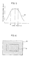
- Fig. 5 is a diagram illustrating relation between a lens position and a focusing evaluation value.
- the abscissa indicates positions of a lens
- the ordinate indicates focusing evaluation values
- the curve 40 indicates characteristics of focusing evaluation values of high frequency components.
- the lens position P in the figure denotes a position of a lens when it is in a complete in-focus state.
- the focusing evaluation value takes its maximum value at the lens position P.
- the focusing evaluation value monotonously increases or monotonously decreases at each of positions Q and R before and after the lens position P.
- a focusing evaluation value is obtained for each field, for example.
- the obtained focusing evaluation value is compared with a focusing evaluation value one field before.
- the lens is further moved in the same direction as before.
- the focusing evaluation value one field before is larger than the present focusing evaluation value, the lens is moved in the opposite direction. This is because, as seen from Fig. 5, a determination can be made that the position of lens has gone over the in-focus position P.
- the lens is stopped at a position where a focusing evaluation value the same as a focusing evaluation value one field before can be obtained.
- a lens is at lens position Q of Fig. 5 in an initial state.
- a focusing evaluation value starts decreasing when the lens goes over the infocus position P and reaches the position R by the abovedescribed mountain climbing control. Accordingly, the lens is returned in a negative direction and stopped at the in-focus position P. By doing so, the lens automatically moves to a position of an in-focus state.
- an object is generally located on a central portion of a field 50 in image sensing.
- the target of focusing is usually not the entirety of field 50 but a focusing control area 51 which is a part in the center.
- control is generally performed by checking whether a plurality of focusing evaluation values are continuously increasing, or decreasing.
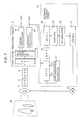
- Fig. 7 is a block diagram illustrating structure of one example of a video camera having a conventional automatic focusing device.
- the video camera includes a lens system 2, a CCD (Charge Coupled Device) 3 provided on a light-receiving surface arranged at a position where an image of an object 30 is formed by lens system 2 for converting an image of the object into an electrical signal, a CDS (Correlation Double Sampling) circuit 4 for correlation-double-sampling a signal provided from CCD 3 as an output, a video signal processing circuit 5 for processing a signal sampled by CDS circuit 4 and outputs video signals (a luminance signal Yout, a chroma signal Cout), a motor 6 for moving a focusing lens included in lens system 2, and an automatic focusing device 1a for determining a direction of moving the focusing lens for focusing by processing a luminance signal Yout outputted by video signal processing circuit 5 to obtain a focusing evaluation value for controlling motor 6.
- a CCD Charge Coupled Device
- Video signal processing circuit 5 includes an AGC (Auto Gain Control) circuit 7 for amplifying a signal outputted by CDS circuit 4 to a predetermined level, a color separating circuit 8 for separating a signal outputted by AGC circuit 7 into a luminance signal and two color difference signals for outputting, a chroma processing circuit 9 for processing color difference signals outputted from color separating circuit 8 and outputting the same as a chroma signal Cout, and a luminance processing circuit 10 for receiving a luminance signal from color separating circuit 8 and outputting the same as an output luminance signal Yout.
- AGC Automatic Gain Control
- Automatic focusing device 1a includes a synchronization separating circuit 11 for separating a vertical synchronization signal Vs and a horizontal synchronization signal Hs from a luminance signal Yout, a gate circuit 12 responsive to synchronization signals Vs and Hs provided from synchronization separating circuit 11 for passing only a signal corresponding to focusing controlled area 51 shown in Fig.
- a BPF (bandpass filter) 13 for passing only high frequency components in a signal provided from gate circuit 12, a detecting circuit 16 for detecting a level of a signal outputted by BPF 13, a sampling circuit 24 for sampling a signal outputted by detecting circuit 16 at a predetermined frequency, an accumulating circuit 23 for obtaining a focusing evaluation value by accumulating a value outputted by sampling circuit 24 over one field, for example, and controlling circuit 21 for controlling movement of motor 6 so that a focusing lens is moved to an in-focus position on the basis of focusing evaluation values outputted by accumulating circuit 23.
- BPF bandpass filter
- a conventional video camera having such an automatic focusing device 1a operates as described below.
- Lens system 2 forms an image of object 30 on a light receiving plane of CCD 3.
- CCD 3 converts the formed image of object 30 into an electric signal by photoelectric conversion.
- CDS circuit 4 correlation-double-samples a signal outputted from CCD 3 and provides it to AGC circuit 7.
- AGC circuit 7 amplifies a level of a signal outputted from CDS circuit 4 to a predetermined level and applies the same to color separating circuit 8.
- Color separating circuit 8 separates a signal amplified by AGC circuit 7 into color difference signals and a luminance signal and provides the color difference signals to chroma processing circuit 9 and the luminance signal to luminance processing circuit 10, respectively.
- Chroma processing circuit 9 processes color difference signals provided from color separating circuit 8 and externally outputs the same as a chroma signal Cout.
- Luminance processing circuit 10 processes a luminance signal applied from color separating circuit 8 and externally outputs the same as an output luminance signal Yout. Luminance signal Yout is also applied to gate circuit 12 and synchronization separating circuit 11 of automatic focusing device 1a.
- Synchronization separating circuit 11 separates a vertical synchronization signal Vs and a horizontal synchronization signal Hs from a luminance signal Yout and provides the same to gate circuit 12.
- Gate circuit 12 applies a luminance signal to BPF 13 in synchronization with a vertical synchronization signal Vs, a horizontal synchronization signal Hs and a predetermined clock signal only when a position which is currently being scanned is inside focusing controlled area 51 shown in Fig. 6.
- BPF 13 extracts only predetermined high frequency band components in the luminance signal outputted from gate circuit 12 and provides the same to detecting circuit 16.
- Detecting circuit 16 detects a level of a signal of the provided high frequency band components and provides the same to sampling circuit 24.
- Sampling circuit 24 samples a level signal outputted from detecting circuit 16 at a predetermined frequency and provides the same to accumulating circuit 23.
- Accumulating circuit 23 accumulates a signal applied from sampling circuit 24 for one field and applies the same to control circuit 21. An accumulated value indicates a focusing evaluation value of that field.
- Control circuit 21 controls motor 6 on the basis of the focusing evaluation value provided from accumulating circuit 23 to move the focusing lens to an in-focus position by the above-described mountain climbing control. The automatic focusing process is thus performed by moving the focusing lens inside a lens system to an in-focus position using focusing evaluation values.
- the above-described conventional automatic focusing device has the following problems.
- a determination is made as to whether it is now in an increasing direction toward a peak or it has already gone over the peak by checking whether a plurality of focusing evaluation values are continuously increasing or decreasing. For example, if focusing evaluation values are continuously increasing twice or more, it is regarded that it is now in an increasing direction toward the peak and the focusing lens is moved in the same direction as before, and on the other hand, if they are continuously decreasing twice or more, a determination can be made that it has already gone over the peak, and the focusing lens is moved in the opposite direction.
- the above-described method can not make correct determinations. That is, as shown by the first through eighth focusing evaluation values in Fig. 3A, even though the focusing evaluation values are apparently becoming smaller on the whole, a determination that it has already passed the peak cannot be made. In this case, a determination is made that it has already gone over the peak only by seeing the seventh through ninth focusing evaluation values.
- a focusing evaluation value may vary largely having no connection with positions of a focusing lens. That is to say, when a focusing evaluation value varies without any order as shown in the variation of the first through ninth values of Fig. 3B, a problem similar to the above-described one occurs. In such a case, since the reliability of focusing evaluation values is low, hunting and so forth may occur or it may largely get out of focus in conventional apparatus.
- an automatic focusing device includes a lens group by which movement a focused field of an object changes, a drive motor for moving the lens group, an extracting circuit for image-sensing an object through the lens group to extract a luminance signal, a signal outputting circuit for outputting a focusing evaluation value signal for evaluating a focusing condition of an object on the basis of the extracted luminance signal, a determining circuit for determining reliability of the outputted focusing evaluation value signal, and a control circuit for controlling the drive motor to improve the focusing condition of the object on the basis of the determined reliability.
- Fig. 1 is a block diagram illustrating a structure of a video camera according to one embodiment of the present invention.
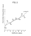
- Fig. 2 is a graph showing one example of processing contents of the LSC circuit of Fig. 1.
- Fig. 3A is a schematic diagram illustrating one example of variation of focusing evaluation values.
- Fig. 3B is a schematic diagram illustrating another example of variation of focusing evaluation values.
- Fig. 4 is a flow chart illustrating one example of a program executed in the control circuit of Fig. 1.
- Fig. 5 is a characteristic diagram of focusing evaluation values for showing general principle of mountain climbing control.
- Fig. 6 is a schematic diagram of a general image-sensing field.
- Fig. 7 is a block diagram illustrating a structure of a video camera using a conventional automatic focusing device.
- Fig. 1 is a block diagram of a video camera provided with an automatic focusing device 1 according to one embodiment of the present invention.
- the video camera shown in the figure is the same as that shown in Fig. 7 except for a part of automatic focusing device 1.
- the same characters and names are allotted to the same parts and functions thereof are also the same. Accordingly, detailed description about the overlapping parts is not repeated herein.
- an LSC (Least Squares Calculation) circuit 22 is provided between accumulating circuit 23 and a control circuit 21 for sampling for a predetermined period focusing evaluation values outputted from accumulating circuit 23, carrying out approximation by the method of least squares, and detecting a trend of variation of focusing evaluation values and a degree of reliability thereof (referred to as a focusing variation value hereinafter), and an output thereof is supplied to control circuit 21.
- Control circuit 21 controls rotation of a motor 6 on the basis of focusing evaluation values outputted from accumulating circuit 23 and a focusing variation value outputted from LSC circuit 22 to move a focusing lens in a lens system 2 to an in-focus position.
- Fig. 2 is a graph for description of one example of operation by the LSC circuit 22 shown in Fig. 1.
- focusing evaluation values inputted into LSC circuit 22 are sampled eight times, for example, which are expressed as DO through D7 in order. Then, supposing a two-dimensional coordinate system in which the x axis corresponds to the order of focusing evaluation values (zero through seven, herein) and the y axis corresponds to magnitudes of focusing evaluation values, DO through D7 are respectively plotted therein.
- the table below indicates it.
- the gradient "a” and the intercept "b” can be calculated with the figures in the table using the method of least squares as shown in the following expressions (1) and (2).
- the calculated gradient a and the residual sum of squares r are outputted to control circuit 21 as focusing variation values A and R, respectively.
- the gradient a is approximately 5.42
- the intercept b is approximately 16.7
- the residual sum of squares r is approximately 190
- a focusing variation value A 5.42
- the focusing variation value A indicates trend of variation of focusing evaluation values and the focusing variation value R indicates the degree of reliability of variation of focusing evaluation values.
- Control circuit 21 always monitors a focusing evaluation value outputted from accumulating circuit 23, and a focusing variation value A and a focusing variation value R outputted by LSC circuit 22. Then, if the focusing variation value R is within a predetermined range, it makes a determination that the reliability of focusing evaluation values is high and performs control with continuous variation of focusing evaluation values as before. However, if, in spite that a focusing variation value A has a negative value and its absolute value exceeds a predetermined range, focusing evaluation values are not continuously decreasing, such variation as shown in Fig. 3A may be occurring, so that a determination is made that the peak has been gone over and the focusing lens is moved in the opposite direction.
- a focusing variation value R exceeds a predetermined range, since it can be considered that focusing evaluation values are varying without any order as shown in Fig. 3B, a determination is made that the reliability of focusing evaluation values is low, and focusing control is once interrupted and the focusing lens is stopped at that position. Then, after waiting for the focusing variation value R to come in the predetermined range, focusing control is started again.
- control circuit 21 is realized with a microcomputer or the like.
- Fig. 4 is a flow chart of one example of a program executed in control circuit 21. As shown in Fig. 4, the program performs control in the following steps.
- step S001 an attempt of detection of a sampling pulse is made
- step S002 a determination is made as to whether detection of sampling pulse could be carried out or not. If the answer of the determination is YES, control proceeds to step S003, and if the answer of the determination is NO, control returns to step S001.
- step S003 a focusing evaluation value and focusing variation values A and R are sampled. Control proceeds to step S004 thereafter.
- step S004 a value of focusing variation value R is checked.
- step S005 a determination is made as to whether the checked value exceeds a predetermined value or not. If the answer of the determination is YES, since the reliability of the detected focusing evaluation value is low, control moves to step S201, and if the answer is NO, it proceeds to step S006.
- step S006 mountain climbing control with focusing evaluation values is performed.
- step S007 as a result of mountain climbing control, a determination is made as to whether an in-focus state has been accomplished or not. If the answer of the determination is YES, control proceeds to step S301 to stop automatic focusing operation, and if the answer is NO, it proceeds to step S008.
- step S008 a determination is made as to whether it has passed the peak or not. If the answer of the determination is YES, it proceeds to step S009 to reversely move the focusing lens, and if the answer is NO, a determination is made that it has not gone over the peak yet and the control moves to step S101.
- step S009 the focusing lens is moved in a direction opposite to that before. Subsequently, control returns to step S001.
- step S101 When it proceeds to step S101, next, a value of focusing variation value A is checked. Control proceeds to step S102.
- step S102 a determination is made as to whether the checked data is negative, and also its absolute value exceeds a predetermined value or not. If the answer of determination is YES, it can be considered that the focusing evaluation value has a trend of decreasing and is changing as shown in Fig. 3A, and the control proceeds to step S009. On the other hand, if the answer is NO, control moves to step S103 to move the focusing lens in the same direction.
- step S103 the focusing lens is moved in the same direction as before. Subsequently, control returns to step S001.
- step S201 When moving to step S201, since a determination is made that the reliability of focusing evaluation values is low, focusing is once stopped. Control returns to step S001 thereafter.
- step S301 If it proceeds to step S301, because an in-focus point is reached, focusing is completely stopped. The processing of automatical focusing operation is then finished.
- Control circuit 21 executes a program for controlling according to the flow chart shown in Fig. 4, so that focusing operation can be surely carried out regardless of variation of focusing evaluation values. Therefore, problems, such as largely coming out of focus, occurrence of hunting and the like can be solved.
- focusing control is performed with trend of variation and reliability of focusing evaluation values, so that automatic focusing control can be surely performed even when image-sensing an object moving in unstable directions.
Landscapes
- Physics & Mathematics (AREA)
- Engineering & Computer Science (AREA)
- General Physics & Mathematics (AREA)
- Optics & Photonics (AREA)
- Computer Vision & Pattern Recognition (AREA)
- Computing Systems (AREA)
- Theoretical Computer Science (AREA)
- Multimedia (AREA)
- Signal Processing (AREA)
- Automatic Focus Adjustment (AREA)
- Focusing (AREA)
Applications Claiming Priority (2)
| Application Number | Priority Date | Filing Date | Title |
|---|---|---|---|
| JP71159/91 | 1991-04-03 | ||
| JP3071159A JP2851713B2 (ja) | 1991-04-03 | 1991-04-03 | オートフォーカス装置 |
Publications (3)
| Publication Number | Publication Date |
|---|---|
| EP0507627A2 true EP0507627A2 (fr) | 1992-10-07 |
| EP0507627A3 EP0507627A3 (en) | 1993-03-24 |
| EP0507627B1 EP0507627B1 (fr) | 1996-12-04 |
Family
ID=13452575
Family Applications (1)
| Application Number | Title | Priority Date | Filing Date |
|---|---|---|---|
| EP92302995A Expired - Lifetime EP0507627B1 (fr) | 1991-04-03 | 1992-04-03 | Dispositif et méthode de focalisation automatique |
Country Status (8)
| Country | Link |
|---|---|
| US (1) | US5337084A (fr) |
| EP (1) | EP0507627B1 (fr) |
| JP (1) | JP2851713B2 (fr) |
| KR (1) | KR960002898B1 (fr) |
| CA (1) | CA2064528C (fr) |
| DE (1) | DE69215571T2 (fr) |
| ES (1) | ES2094874T3 (fr) |
| MY (1) | MY107864A (fr) |
Cited By (1)
| Publication number | Priority date | Publication date | Assignee | Title |
|---|---|---|---|---|
| CN102053339A (zh) * | 2010-11-23 | 2011-05-11 | 天津市亚安科技电子有限公司 | 自动聚焦方法 |
Families Citing this family (14)
| Publication number | Priority date | Publication date | Assignee | Title |
|---|---|---|---|---|
| JPH0787376A (ja) * | 1993-06-22 | 1995-03-31 | Canon Inc | 合焦情報検出装置 |
| US6163340A (en) * | 1995-03-27 | 2000-12-19 | Canon Kabushiki Kaisha | Automatic focus adjusting device |
| US6373524B2 (en) * | 1995-06-22 | 2002-04-16 | Canon Kabushiki Kaisha | Interchangeable lens video camera system |
| US5874994A (en) * | 1995-06-30 | 1999-02-23 | Eastman Kodak Company | Filter employing arithmetic operations for an electronic sychronized digital camera |
| JP2000147370A (ja) * | 1998-11-18 | 2000-05-26 | Sony Corp | 撮像装置 |
| US7079187B1 (en) * | 1998-11-19 | 2006-07-18 | Canon Kabushiki Kaisha | Focus adjusting apparatus and focus adjusting method |
| JP2006106484A (ja) * | 2004-10-07 | 2006-04-20 | Pentax Corp | 焦点検出方法 |
| CN100543574C (zh) * | 2004-10-22 | 2009-09-23 | 亚洲光学股份有限公司 | 自动对焦方法以及电子照相机的自动对焦装置 |
| CN1896859B (zh) * | 2005-07-14 | 2010-08-25 | 亚洲光学股份有限公司 | 自动对焦方法以及使用该方法的电子装置 |
| JP4979558B2 (ja) * | 2007-12-10 | 2012-07-18 | 日本放送協会 | レンズ姿勢/位置調整方法および装置 |
| JP2012002951A (ja) * | 2010-06-15 | 2012-01-05 | Ricoh Co Ltd | 撮像装置、合焦位置検出方法および合焦位置検出プログラム |
| US9288379B2 (en) * | 2014-03-12 | 2016-03-15 | Omnivision Technologies, Inc. | System and method for continuous auto focus within camera module |
| JP5857100B2 (ja) * | 2014-08-11 | 2016-02-10 | オリンパス株式会社 | 撮像装置 |
| TW201830168A (zh) | 2016-12-08 | 2018-08-16 | 美商精微超科技公司 | 用於重構晶圓之微影製程之對焦控制的掃描方法 |
Family Cites Families (12)
| Publication number | Priority date | Publication date | Assignee | Title |
|---|---|---|---|---|
| JPS58113807A (ja) * | 1981-12-28 | 1983-07-06 | Canon Inc | 距離測定装置 |
| US4600832A (en) * | 1983-10-28 | 1986-07-15 | Nanometrics Incorporated | Method and apparatus for automatic optical focusing on an optically discernible feature on an object |
| FR2575888B1 (fr) * | 1985-01-04 | 1987-02-20 | Thomson Csf | Procede et dispositif de mise au point d'une camera et camera comportant un tel dispositif |
| JPS61210310A (ja) * | 1985-03-15 | 1986-09-18 | Nippon Kokan Kk <Nkk> | 自動焦点合せ装置 |
| JPS63178523A (ja) * | 1987-01-20 | 1988-07-22 | Toshiba Corp | 自動焦点合わせ方法 |
| JPH01160263A (ja) * | 1987-12-17 | 1989-06-23 | Tamuron:Kk | ビデオカメラの自動焦点調節装置 |
| US5005086A (en) * | 1988-03-04 | 1991-04-02 | Sony Corporation | Focus control apparatus having two focusing speeds |
| AU612484B2 (en) * | 1988-05-11 | 1991-07-11 | Sanyo Electric Co., Ltd. | Image sensing apparatus having automatic focusing function of automatically matching focus in response to video signal |
| US4945220A (en) * | 1988-11-16 | 1990-07-31 | Prometrix Corporation | Autofocusing system for microscope having contrast detection means |
| US5193124A (en) * | 1989-06-29 | 1993-03-09 | The Research Foundation Of State University Of New York | Computational methods and electronic camera apparatus for determining distance of objects, rapid autofocusing, and obtaining improved focus images |
| JP2971892B2 (ja) * | 1989-07-18 | 1999-11-08 | 株式会社フローベル | オートフォーカス方式 |
| JPH06172967A (ja) * | 1992-12-01 | 1994-06-21 | Nissin Electric Co Ltd | 窒化ホウ素含有膜被覆基体とその製造方法 |
-
1991
- 1991-04-03 JP JP3071159A patent/JP2851713B2/ja not_active Expired - Fee Related
-
1992
- 1992-03-31 CA CA002064528A patent/CA2064528C/fr not_active Expired - Lifetime
- 1992-04-02 KR KR1019920005507A patent/KR960002898B1/ko not_active Expired - Fee Related
- 1992-04-02 MY MYPI92000570A patent/MY107864A/en unknown
- 1992-04-02 US US07/862,361 patent/US5337084A/en not_active Expired - Lifetime
- 1992-04-03 ES ES92302995T patent/ES2094874T3/es not_active Expired - Lifetime
- 1992-04-03 DE DE69215571T patent/DE69215571T2/de not_active Expired - Lifetime
- 1992-04-03 EP EP92302995A patent/EP0507627B1/fr not_active Expired - Lifetime
Cited By (2)
| Publication number | Priority date | Publication date | Assignee | Title |
|---|---|---|---|---|
| CN102053339A (zh) * | 2010-11-23 | 2011-05-11 | 天津市亚安科技电子有限公司 | 自动聚焦方法 |
| CN102053339B (zh) * | 2010-11-23 | 2014-04-16 | 天津市亚安科技股份有限公司 | 自动聚焦方法 |
Also Published As
| Publication number | Publication date |
|---|---|
| MY107864A (en) | 1996-06-29 |
| EP0507627A3 (en) | 1993-03-24 |
| US5337084A (en) | 1994-08-09 |
| CA2064528A1 (fr) | 1992-10-04 |
| ES2094874T3 (es) | 1997-02-01 |
| DE69215571T2 (de) | 1997-05-28 |
| KR960002898B1 (ko) | 1996-02-27 |
| CA2064528C (fr) | 1999-01-26 |
| DE69215571D1 (de) | 1997-01-16 |
| KR920020934A (ko) | 1992-11-21 |
| EP0507627B1 (fr) | 1996-12-04 |
| JP2851713B2 (ja) | 1999-01-27 |
| JPH04305609A (ja) | 1992-10-28 |
Similar Documents
| Publication | Publication Date | Title |
|---|---|---|
| US5337084A (en) | Automatic focusing device utilizing a trend of variation and degree of reliability of a focusing evaluation value signal to improve image focusing | |
| EP0605240B1 (fr) | Circuit intégré monopuce pour dispositif de commande de focalisation | |
| US9007514B2 (en) | Focus adjusting apparatus and method | |
| EP0794660A1 (fr) | Procédé et dispositif de mise au point automatique | |
| EP0573986A1 (fr) | Dispositif de focalisation automatique pour caméra vidéo | |
| EP0331502B1 (fr) | Appareil et méthode de contrôle de focalisation | |
| US4969044A (en) | Automatic focusing system for use in cameras having zooming function | |
| JPH04133576A (ja) | 撮像装置 | |
| JP3218408B2 (ja) | 焦点自動検出装置 | |
| EP0512430B1 (fr) | Dispositif de focalisation automatique | |
| JP3112491B2 (ja) | オートフォーカシングシステム | |
| JPH10164424A (ja) | オートフォーカス装置 | |
| JP3134307B2 (ja) | オートフォーカス回路 | |
| JP3430647B2 (ja) | オートフォーカス回路 | |
| JPH0662305A (ja) | 自動合焦装置 | |
| JP3098144B2 (ja) | オートフォーカス装置 | |
| JP2742741B2 (ja) | オートフォーカス装置 | |
| KR0128531B1 (ko) | 캠코더의 자동촛점 조절장치 | |
| JPH05236328A (ja) | 撮像装置 | |
| JPH03237883A (ja) | 自動合焦装置 | |
| JP2691316B2 (ja) | オートフォーカス装置 | |
| JP3251006B2 (ja) | オートフォーカス装置 | |
| JPH06268895A (ja) | オートフォーカス装置 | |
| JPH0771207B2 (ja) | オ−トフオ−カス方式 | |
| JPH0553041A (ja) | レンズ制御装置 |
Legal Events
| Date | Code | Title | Description |
|---|---|---|---|
| PUAI | Public reference made under article 153(3) epc to a published international application that has entered the european phase |
Free format text: ORIGINAL CODE: 0009012 |
|
| AK | Designated contracting states |
Kind code of ref document: A2 Designated state(s): DE ES FR GB NL |
|
| PUAL | Search report despatched |
Free format text: ORIGINAL CODE: 0009013 |
|
| AK | Designated contracting states |
Kind code of ref document: A3 Designated state(s): DE ES FR GB NL |
|
| 17P | Request for examination filed |
Effective date: 19930318 |
|
| 17Q | First examination report despatched |
Effective date: 19950308 |
|
| GRAG | Despatch of communication of intention to grant |
Free format text: ORIGINAL CODE: EPIDOS AGRA |
|
| GRAH | Despatch of communication of intention to grant a patent |
Free format text: ORIGINAL CODE: EPIDOS IGRA |
|
| GRAH | Despatch of communication of intention to grant a patent |
Free format text: ORIGINAL CODE: EPIDOS IGRA |
|
| GRAA | (expected) grant |
Free format text: ORIGINAL CODE: 0009210 |
|
| AK | Designated contracting states |
Kind code of ref document: B1 Designated state(s): DE ES FR GB NL |
|
| REF | Corresponds to: |
Ref document number: 69215571 Country of ref document: DE Date of ref document: 19970116 |
|
| REG | Reference to a national code |
Ref country code: ES Ref legal event code: FG2A Ref document number: 2094874 Country of ref document: ES Kind code of ref document: T3 |
|
| ET | Fr: translation filed | ||
| PLBE | No opposition filed within time limit |
Free format text: ORIGINAL CODE: 0009261 |
|
| STAA | Information on the status of an ep patent application or granted ep patent |
Free format text: STATUS: NO OPPOSITION FILED WITHIN TIME LIMIT |
|
| 26N | No opposition filed | ||
| REG | Reference to a national code |
Ref country code: GB Ref legal event code: IF02 |
|
| PGFP | Annual fee paid to national office [announced via postgrant information from national office to epo] |
Ref country code: GB Payment date: 20100325 Year of fee payment: 19 |
|
| PGFP | Annual fee paid to national office [announced via postgrant information from national office to epo] |
Ref country code: FR Payment date: 20100521 Year of fee payment: 19 Ref country code: ES Payment date: 20100423 Year of fee payment: 19 |
|
| PGFP | Annual fee paid to national office [announced via postgrant information from national office to epo] |
Ref country code: DE Payment date: 20100430 Year of fee payment: 19 Ref country code: NL Payment date: 20100416 Year of fee payment: 19 |
|
| REG | Reference to a national code |
Ref country code: NL Ref legal event code: V1 Effective date: 20111101 |
|
| GBPC | Gb: european patent ceased through non-payment of renewal fee |
Effective date: 20110403 |
|
| REG | Reference to a national code |
Ref country code: FR Ref legal event code: ST Effective date: 20111230 |
|
| PG25 | Lapsed in a contracting state [announced via postgrant information from national office to epo] |
Ref country code: NL Free format text: LAPSE BECAUSE OF NON-PAYMENT OF DUE FEES Effective date: 20111101 Ref country code: FR Free format text: LAPSE BECAUSE OF NON-PAYMENT OF DUE FEES Effective date: 20110502 Ref country code: DE Free format text: LAPSE BECAUSE OF NON-PAYMENT OF DUE FEES Effective date: 20111101 |
|
| PG25 | Lapsed in a contracting state [announced via postgrant information from national office to epo] |
Ref country code: GB Free format text: LAPSE BECAUSE OF NON-PAYMENT OF DUE FEES Effective date: 20110403 |
|
| REG | Reference to a national code |
Ref country code: DE Ref legal event code: R119 Ref document number: 69215571 Country of ref document: DE Effective date: 20111101 |
|
| REG | Reference to a national code |
Ref country code: ES Ref legal event code: FD2A Effective date: 20120524 |
|
| PG25 | Lapsed in a contracting state [announced via postgrant information from national office to epo] |
Ref country code: ES Free format text: LAPSE BECAUSE OF NON-PAYMENT OF DUE FEES Effective date: 20110404 |