EP0508246B1 - Stopfenstange mit verschliessfester Hülse - Google Patents
Stopfenstange mit verschliessfester Hülse Download PDFInfo
- Publication number
- EP0508246B1 EP0508246B1 EP92105388A EP92105388A EP0508246B1 EP 0508246 B1 EP0508246 B1 EP 0508246B1 EP 92105388 A EP92105388 A EP 92105388A EP 92105388 A EP92105388 A EP 92105388A EP 0508246 B1 EP0508246 B1 EP 0508246B1
- Authority
- EP
- European Patent Office
- Prior art keywords
- stopper rod
- sleeve
- erosion
- stopper
- rod according
- Prior art date
- Legal status (The legal status is an assumption and is not a legal conclusion. Google has not performed a legal analysis and makes no representation as to the accuracy of the status listed.)
- Expired - Lifetime
Links
- 230000003628 erosive effect Effects 0.000 title claims description 21
- 239000000463 material Substances 0.000 claims description 24
- 229910000831 Steel Inorganic materials 0.000 claims description 19
- 239000010959 steel Substances 0.000 claims description 19
- 239000000843 powder Substances 0.000 claims description 17
- CPLXHLVBOLITMK-UHFFFAOYSA-N Magnesium oxide Chemical compound [Mg]=O CPLXHLVBOLITMK-UHFFFAOYSA-N 0.000 claims description 12
- MCMNRKCIXSYSNV-UHFFFAOYSA-N Zirconium dioxide Chemical compound O=[Zr]=O MCMNRKCIXSYSNV-UHFFFAOYSA-N 0.000 claims description 12
- 239000007788 liquid Substances 0.000 claims description 9
- 238000007654 immersion Methods 0.000 claims description 6
- 239000000395 magnesium oxide Substances 0.000 claims description 6
- OKTJSMMVPCPJKN-UHFFFAOYSA-N Carbon Chemical compound [C] OKTJSMMVPCPJKN-UHFFFAOYSA-N 0.000 claims description 5
- 238000009749 continuous casting Methods 0.000 claims description 5
- 229910002804 graphite Inorganic materials 0.000 claims description 5
- 239000010439 graphite Substances 0.000 claims description 5
- 238000000034 method Methods 0.000 claims description 5
- 230000008569 process Effects 0.000 claims description 4
- 238000000462 isostatic pressing Methods 0.000 claims description 2
- 239000002893 slag Substances 0.000 description 9
- 239000002184 metal Substances 0.000 description 8
- 229910052751 metal Inorganic materials 0.000 description 8
- 238000005266 casting Methods 0.000 description 6
- 229910001338 liquidmetal Inorganic materials 0.000 description 3
- XKRFYHLGVUSROY-UHFFFAOYSA-N Argon Chemical compound [Ar] XKRFYHLGVUSROY-UHFFFAOYSA-N 0.000 description 2
- XEEYBQQBJWHFJM-UHFFFAOYSA-N Iron Chemical compound [Fe] XEEYBQQBJWHFJM-UHFFFAOYSA-N 0.000 description 2
- VYPSYNLAJGMNEJ-UHFFFAOYSA-N Silicium dioxide Chemical compound O=[Si]=O VYPSYNLAJGMNEJ-UHFFFAOYSA-N 0.000 description 2
- PNEYBMLMFCGWSK-UHFFFAOYSA-N aluminium oxide Inorganic materials [O-2].[O-2].[O-2].[Al+3].[Al+3] PNEYBMLMFCGWSK-UHFFFAOYSA-N 0.000 description 2
- 230000008901 benefit Effects 0.000 description 2
- 238000003825 pressing Methods 0.000 description 2
- 239000011819 refractory material Substances 0.000 description 2
- 230000003313 weakening effect Effects 0.000 description 2
- 240000001398 Typha domingensis Species 0.000 description 1
- 230000009471 action Effects 0.000 description 1
- 239000012080 ambient air Substances 0.000 description 1
- 229910052786 argon Inorganic materials 0.000 description 1
- 239000007789 gas Substances 0.000 description 1
- 239000012535 impurity Substances 0.000 description 1
- 238000009434 installation Methods 0.000 description 1
- 229910052742 iron Inorganic materials 0.000 description 1
- 238000004519 manufacturing process Methods 0.000 description 1
- 230000007246 mechanism Effects 0.000 description 1
- 230000007935 neutral effect Effects 0.000 description 1
- 230000003647 oxidation Effects 0.000 description 1
- 238000007254 oxidation reaction Methods 0.000 description 1
- 230000009467 reduction Effects 0.000 description 1
- 230000001105 regulatory effect Effects 0.000 description 1
- 239000000377 silicon dioxide Substances 0.000 description 1
Images
Classifications
-
- B—PERFORMING OPERATIONS; TRANSPORTING
- B22—CASTING; POWDER METALLURGY
- B22D—CASTING OF METALS; CASTING OF OTHER SUBSTANCES BY THE SAME PROCESSES OR DEVICES
- B22D41/00—Casting melt-holding vessels, e.g. ladles, tundishes, cups or the like
- B22D41/14—Closures
- B22D41/16—Closures stopper-rod type, i.e. a stopper-rod being positioned downwardly through the vessel and the metal therein, for selective registry with the pouring opening
- B22D41/18—Stopper-rods therefor
Definitions
- the continuous casting process of steel is currently mainly used in the steel industry.
- the liquid steel, at its outlet from the converter is poured into a large capacity pocket, then poured into a smaller capacity distributor which allows it to be continuously cast in one or more molds.
- a stopper is an elongated piece of refractory material that dips into liquid steel. Its lower end is applied to the seat of a tap hole provided in the bottom of the distributor. An arm fixed at its upper part makes it possible to move its lower end more or less away from the seat of the tap hole and thus to regulate or stop the flow of the metal.
- Rotary devices are also known in which the flow of metal is controlled by rotation.
- the free surface of the molten metal contained both in the pocket and in the distributor is covered with a covering powder, generally of a synthetic nature.
- This powder has several functions. It prevents oxidation of the metal by isolating it from the ambient air, reduces heat losses, and traps inclusions which rise to the surface of the steel.
- This slag also has a corrosive action on the distaff.
- the combined erosion of the slag and the covering powder causes the appearance of a weakening of the section of the stopper rod at its level of immersion in the liquid metal. This reduction in section weakens the stopper rod and can cause it to break. Such a rupture leads to the loss of control over the flow of the metal. All of the metal contained in the distributor is then lost and can cause considerable damage to the continuous casting mold and to the entire installation. This also involves considerable risks for personnel in the vicinity of the dispatcher. It is therefore absolutely essential to avoid any risk of the stopper breaking.
- Documents FR-A-2 467 769 and JP-A-63 104 760 describe nozzles for the continuous casting of steel comprising erosion-resistant sleeves arranged in a fixed position relative to the level of the steel in the mold.
- Document JP-A 113 0857 describes a stopper comprising a cuff made essentially of silica and disposed over the entire height of the stopper to prevent the alumina forming the stopper from dissolving in the steel.
- the present invention relates to a stopper rod which overcomes these drawbacks. It has increased resistance to erosion from both slag and covering powder. It therefore allows a longer casting sequence without risk of breakage. It also applies to rotary mechanisms (rotary valves).
- This stopper has an elongated body obtained by isostatic pressing of a first material, to regulate the flow of liquid steel from a distributor containing a substantially constant amount of liquid steel to a continuous casting mold, a layer of cover powder floating on the surface of the liquid steel.
- It is characterized in that it comprises an erosion-resistant cuff surrounding the body, extending over only part of the height of the body, and situated in the longitudinal direction of the stopper rod at a height such that, when the the stopper rod is in operation, the cuff is at the level of the stopper immersion line, the cuff having a height sufficient to take account of slight variations in height at the steel level as well as the movements of the stopper rod at the during its operation, said sleeve being made of a second material having high characteristics of resistance to erosion by the covering powder.
- the material having particularly high characteristics of resistance to erosion can be chosen from the group comprising zirconia, magnesia, graphitized zirconia, graphitized magnesia.
- the stopper of the invention comprises an elongated body having an extra thickness.
- This extra thickness can be constituted by the material of the body itself.
- the stopper rod is made of a single material.
- the additional thickness may be constituted, at least in part, by a cuff made of a second material different from that of the body.
- this second material has high characteristics of resistance to erosion by the slag and the covering powder.
- the cuff can be made in one piece and fixed or cemented on the surface outside of the body. It can also be made in two or more parts, which then makes it possible to insert it into a recess made in the body. If the depth of this recess corresponds to the thickness of the cuff, the latter will not form any additional thickness.
- the invention also relates to a stopper production method characterized in that said cuff is first shaped separately from the body, for example by hydraulic pressing and then pressed isostatically at the same time as the body.
- said powder of the material forming the ring is introduced into the mold at the same time as the powder of the material constituting the body of the stopper rod.
- the assembly is then isostatically co-pressed in a single operation.
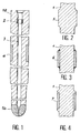
- FIG. 1 shows an overall view of a stopper rod produced in accordance with a first embodiment of the invention.
- This stopper rod has a body 1 of generally elongated shape, having an upper part 1a and a lower part 1b.
- fixing means for example a metal insert such as 2, or any other fixing means making it possible to fix the stopper rod to a lever.
- the lower part of the stopper rod ends with a rounded or conical nose intended to fit on a seat provided in the bottom of a distributor (not shown).
- the stopper's nose is made of a material different from that of the body in order to give it increased resistance in this area which is particularly subject to erosion. However, this characteristic is not essential.
- the nose could be made of the same material as the body.
- the stopper rod is traversed right through by a longitudinal channel 3 which opens at the lower end of the nose. This channel is used to inject a neutral gas such as argon.
- the stopper rod has a cuff 4 having increased resistance to erosion.
- this cuff 4 is made of a material different from the material of the body.
- the body can be made of graphite alumina, while the cuff 4 will be made of magnesia, zirconia, graphite zirconia, graphite magnesia or another adopted material. It is noted that the cuff 4 does not form any additional thickness relative to the body. It can be carried out according to different methods.
- the cuff is produced separately, for example by hydraulic pressing, then it is placed in the mold which gives its shape to the body which is then filled with the powder of the material forming the body. The assembly is then isostatically co-pressed.
- the mold is filled with the powder of the material forming the body and with the powder of the material forming the cuff. The latter is then isostatically co-pressed in a single operation.
- the cuff can also be produced separately in two or more parts to be inserted into a recess provided in the body and then fixed, for example cemented, in this recess.
- FIG. 2 An alternative embodiment of the stopper of the invention in which the erosion-resistant cuff is constituted by a simple extra thickness made of the same material as the body.
- This variant embodiment is particularly simple to produce. It offers increased resistance to erosion because that the section of the stopper rod is increased at the level of the line of immersion in the molten metal. It therefore makes it possible to extend the duration of the casting campaign in a simple and economical manner.
- FIG. 3 a third alternative embodiment.
- the ring 6 forms an additional thickness relative to the body of the stopper rod. It can be made in a single part then threaded onto the body to be fixed, for example cemented, in an appropriate position on this body.
- the ring 6 could also be made in two or more parts, although this embodiment is of no particular interest since here the body does not have a recess.
- FIG. 4 a fourth alternative embodiment of the stopper of the invention.
- This variant combines the characteristics of Figures 1 and 2.
- the erosion resistant cuff is formed by a ring 7 made of a material having particularly high characteristics of resistance to erosion.
- the cuff 7 forms an extra thickness which increases the cross section of the stopper rod at the level of its immersion in the liquid metal.
- the increase in the resistance to erosion is therefore obtained here both by the characteristics of the material of the sleeve 7 and by an increase in the diameter of the latter.
- This variant like that of FIG. 3, therefore allows particularly long casting sequences.
Landscapes
- Engineering & Computer Science (AREA)
- Mechanical Engineering (AREA)
- Casting Support Devices, Ladles, And Melt Control Thereby (AREA)
- Compositions Of Oxide Ceramics (AREA)
- Lift Valve (AREA)
Claims (7)
- Stopfenstange mit einem durch isostatisches Pressen aus einem ersten Material erhaltenen langgestreckten Stangenkörper (1) zum Regulieren des Ablaufens von Flüssigstahl aus einem eine im wesentlichen konstante Menge an Flüssigstahl enthaltenden Verteiler in eine Stranggießform wobei eine Abdeckpulverschicht auf der Oberfläche des Flüssigstahls schwimmt, und mit einer den Stangenkörper 1 umgebenden Hülse, dadurch gekennzeichnet, daß sich die Hülse (4, 5, 6, 7) nur über einen Teil der Höhe des Stangenkörpers erstreckt und in Längsrichtung der Stopfenstange in einer solchen Höhe angeordnet ist, daß, wenn die Stopfenstange in Betrieb ist, sich die Hülse (4, 5, 6, 7) auf dem Niveau der Eintauchlinie der Stopfenstange befindet, wobei die Hülse eine ausreichende Höhe darbietet, um leichte Höhenveränderungen im Niveau des Stahls sowie Bewegungen der Stopfenstange im Laufe ihres Betriebs zu berücksichtigen, und dadurch, daß die Hülse aus einem zweiten Material (4, 6, 7) hergestellt ist, das erhöhte Festigkeitseigenschaften gegenüber einer Erosion durch das Abdeckpulver darbietet, oder von einer Verdickung (5) des Stangenkörpers (1) gebildet ist.
- Stopfenstange nach Anspruch 1, dadurch gekennzeichnet, daß das die erhöhten Festigkeitseigenschaften gegenüber Erosion darbietende Material aus der Zirkonoxid, Magnesiumoxid, graphitiertes Zirkonoxid und graphietiertes Magnesiumoxid umfassenden Gruppe ausgewählt ist.
- Stopfenstange nach einem der Ansprüche 1 und 2, dadurch gekennzeichnet, daß die erosionsfeste Hülse von einer Verdickung (6, 7) aus dem zweiten Material gebildet ist.
- Stopfenstange nach Anspruch 3, dadurch gekennzeichnet, daß die Verdickung (6) auf der Außenfläche des Stangenkörpers (1) befestigt ist.
- Stopfenstange nach einem der Ansprüche 1 bis 4, dadurch gekennzeichnet, daß sie eine Hülse (4, 7) umfaßt, die aus zumindest zwei Teilen hergestellt und in einer Aussparung des Stangenkörpers (1, 4) oder der verdickung des Stangenkörpers (1, 7) befestigt ist.
- Verfahren zur Herstellung einer Stopfenstange nach einem der Ansprüche 1 bis 5, dadurch gekennzeichnet, daß die Hülse (4, 6, 7) gesondert vom Stangenkörper geformt und dann zugleich mit dem Stangenkörper (1) gemeinsam isostatisch gepreßt wird.
- Verfahren zur Herstellung einer Stopfenstange nach einem der Ansprüche 1 bis 5, dadurch gekennzeichnet, daß die Hülse (4, 7) zugleich mit dem Stangenkörper (1) gemeinsam isostatisch gepreßt wird.
Applications Claiming Priority (2)
| Application Number | Priority Date | Filing Date | Title |
|---|---|---|---|
| FR9104403A FR2675064B1 (fr) | 1991-04-09 | 1991-04-09 | Quenouille comportant une manchette resistant a l'erosion. |
| FR9104403 | 1991-04-09 |
Publications (2)
| Publication Number | Publication Date |
|---|---|
| EP0508246A1 EP0508246A1 (de) | 1992-10-14 |
| EP0508246B1 true EP0508246B1 (de) | 1997-10-08 |
Family
ID=9411703
Family Applications (1)
| Application Number | Title | Priority Date | Filing Date |
|---|---|---|---|
| EP92105388A Expired - Lifetime EP0508246B1 (de) | 1991-04-09 | 1992-03-28 | Stopfenstange mit verschliessfester Hülse |
Country Status (6)
| Country | Link |
|---|---|
| US (1) | US5259596A (de) |
| EP (1) | EP0508246B1 (de) |
| JP (1) | JPH05146867A (de) |
| DE (1) | DE69222557T2 (de) |
| ES (1) | ES2109287T3 (de) |
| FR (1) | FR2675064B1 (de) |
Families Citing this family (17)
| Publication number | Priority date | Publication date | Assignee | Title |
|---|---|---|---|---|
| FR2728491B1 (fr) * | 1994-12-22 | 1997-03-14 | Lorraine Laminage | Dispositif de coulee d'un metal liquide avec injection d'un gaz inerte dans le metal liquide en cours de coulee |
| JP2984206B2 (ja) * | 1995-09-18 | 1999-11-29 | 明智セラミックス株式会社 | 連続鋳造用タンディッシュストッパー |
| US5820815A (en) * | 1996-01-17 | 1998-10-13 | Kennecott Holdings Corporation | Cooled tapping device |
| US5908577A (en) * | 1996-08-26 | 1999-06-01 | Shinagawa Refractories Co., Ltd. | Nozzle for continuous casting |
| CN1284019A (zh) * | 1997-11-27 | 2001-02-14 | 福塞科国际有限公司 | 塞杆 |
| ES2201707T3 (es) * | 1998-05-05 | 2004-03-16 | Didier-Werke Ag | Cuerpo compuesto de ceramica. |
| GB9817645D0 (en) * | 1998-08-14 | 1998-10-07 | Didier Werke Ag | Stopper |
| EP1243361A1 (de) * | 2001-03-19 | 2002-09-25 | Vesuvius Crucible Company | Vorrichtung zum Einleiten von Gasen in eine Metallschmelze |
| SK287594B6 (sk) * | 2001-06-08 | 2011-03-04 | Vesuvius Crucible Company | Žiaruvzdorná monobloková zátková tyč |
| US20060249546A1 (en) * | 2005-05-03 | 2006-11-09 | Foseco International Limited | Tundish stopper rod for continuous molten metal casting |
| ATE485909T1 (de) * | 2008-11-19 | 2010-11-15 | Refractory Intellectual Prop | Stopfenstange |
| US8210402B2 (en) * | 2009-02-09 | 2012-07-03 | Ajf, Inc. | Slag control shape device with L-shape loading bracket |
| CN106513652B (zh) * | 2016-11-16 | 2018-10-09 | 成都先进金属材料产业技术研究院有限公司 | 抗侵蚀的塞棒 |
| CN111470851A (zh) * | 2019-08-27 | 2020-07-31 | 北京利尔高温材料股份有限公司 | 一种整体塞棒用棒身材料 |
| CN112775423A (zh) * | 2021-02-01 | 2021-05-11 | 北京利尔高温材料股份有限公司 | 一种组合整体复合塞棒及其制备方法 |
| CN116890104B (zh) * | 2023-07-14 | 2026-02-24 | 宁波金田铜业(集团)股份有限公司 | 一种抗氧化石墨塞棒及其制备方法 |
| CN119910172A (zh) * | 2025-02-06 | 2025-05-02 | 山西太钢不锈钢股份有限公司 | 一种减轻纯铁连铸生产塞棒侵蚀的方法 |
Citations (1)
| Publication number | Priority date | Publication date | Assignee | Title |
|---|---|---|---|---|
| JPH01130857A (ja) * | 1987-11-18 | 1989-05-23 | Nkk Corp | 連続鋳造用ストッパ |
Family Cites Families (11)
| Publication number | Priority date | Publication date | Assignee | Title |
|---|---|---|---|---|
| US1439522A (en) * | 1922-01-14 | 1922-12-19 | Karl S Howard | Pouring ladle for molten metal |
| US1486694A (en) * | 1923-09-06 | 1924-03-11 | James E Sheaffer | Ladle stopper rod |
| US1776773A (en) * | 1929-07-01 | 1930-09-30 | Vesuvius Crucible Co | Protective device for use in hot-metal ladles |
| US3011231A (en) * | 1957-12-12 | 1961-12-05 | Griffin Wheel Co | Stopper assembly |
| US3456690A (en) * | 1967-05-26 | 1969-07-22 | Vesuvius Crucible Co | Composite sleeve for ladle stopper rods |
| FR2464769A1 (fr) * | 1979-09-10 | 1981-03-20 | Akechi Taikarenga Kk | Busette a immersion pour la coulee continue d'acier |
| GB2123726A (en) * | 1982-07-01 | 1984-02-08 | James Menzies Thornton | Ladle etc. stopper |
| GB8313074D0 (en) * | 1983-05-12 | 1983-06-15 | Thornton J M | Refractory product |
| JPH07227B2 (ja) * | 1985-08-29 | 1995-01-11 | 黒崎窯業株式会社 | 浸漬ノズル及びその製造方法 |
| JPS63104760A (ja) * | 1986-10-20 | 1988-05-10 | Sumitomo Metal Ind Ltd | 連続鋳造用浸漬ノズル |
| US5083687A (en) * | 1989-10-19 | 1992-01-28 | Kawasaki Steel Corporation | Nozzle for continuous casting and method of producing |
-
1991
- 1991-04-09 FR FR9104403A patent/FR2675064B1/fr not_active Expired - Fee Related
-
1992
- 1992-03-28 DE DE69222557T patent/DE69222557T2/de not_active Expired - Fee Related
- 1992-03-28 ES ES92105388T patent/ES2109287T3/es not_active Expired - Lifetime
- 1992-03-28 EP EP92105388A patent/EP0508246B1/de not_active Expired - Lifetime
- 1992-04-07 US US07/864,855 patent/US5259596A/en not_active Expired - Fee Related
- 1992-04-09 JP JP4116888A patent/JPH05146867A/ja active Pending
Patent Citations (1)
| Publication number | Priority date | Publication date | Assignee | Title |
|---|---|---|---|---|
| JPH01130857A (ja) * | 1987-11-18 | 1989-05-23 | Nkk Corp | 連続鋳造用ストッパ |
Also Published As
| Publication number | Publication date |
|---|---|
| US5259596A (en) | 1993-11-09 |
| EP0508246A1 (de) | 1992-10-14 |
| JPH05146867A (ja) | 1993-06-15 |
| FR2675064A1 (fr) | 1992-10-16 |
| DE69222557T2 (de) | 1998-03-05 |
| DE69222557D1 (de) | 1997-11-13 |
| ES2109287T3 (es) | 1998-01-16 |
| FR2675064B1 (fr) | 1995-06-02 |
Similar Documents
| Publication | Publication Date | Title |
|---|---|---|
| EP0508246B1 (de) | Stopfenstange mit verschliessfester Hülse | |
| EP1439016A1 (de) | Giessrohr, Spannvorrichtung für Giessrohr und Giessvorrichtung | |
| EP0305426B1 (de) | Verfahren und vorrichtung zum giessen von flüssigem metall | |
| EP0589762B1 (de) | Giessrohr für Metall und Verfahren zu seiner Herstellung | |
| EP0102292B1 (de) | Rohre für das Giessen von schmelzflüssigem Metall | |
| CN1251063A (zh) | 带有铸造板的耐火材料浇注管 | |
| RU2276630C2 (ru) | Стопорный стержень | |
| BE1000948A3 (fr) | Tube de coulee pour dispositif de fermeture coulissante. | |
| FR2697183A1 (fr) | Busette coulissante pour récipient récepteur d'acier fondu. | |
| WO1995034395A1 (fr) | Piece de coulee comportant une couche externe apte a former une couche impermeable aux gaz et procede de mise en ×uvre | |
| ZA200709898B (en) | Stopper device for controlling a flow of molten metal | |
| FR2488165A1 (fr) | Busette immergee pour coulee continue d'acier fondu | |
| EP0904170B1 (de) | Vertikal stranggusskokille mit aufsatz | |
| FR2521462A1 (fr) | Dispositif d'amenee du metal dans les lingotieres de coulee continue | |
| AU695890B2 (en) | Immersed metallurgical pouring nozzles | |
| FR2643001A1 (fr) | Organe de coulee comportant une surface plane de glissement pour une plaque tiroir associee | |
| FR2541915A2 (fr) | Dispositif d'amenee du metal dans les lingotieres de coulee continue | |
| GB2307876A (en) | Metering nozzle for a tundish | |
| BE683638A (de) | ||
| FR2553317A1 (fr) | Joint pour installation de coulee continue horizontale des metaux notamment de l'acier et installation de coulee equipee de ce joint | |
| EP0836539A1 (de) | Kombination platte-innere ausgussdüse mit einer sollbruchstelle | |
| EP0683706A1 (de) | Giessrohr. | |
| JP2004025223A (ja) | 連続鋳造用ノズル | |
| FR2727339A3 (fr) | Quenouille de repartiteur de coulee continue d'acier | |
| BE888255A (fr) | Perfectionnements au procede de coulee continue des metaux et dispositif pour la mise en oeuvre de ce procede, |
Legal Events
| Date | Code | Title | Description |
|---|---|---|---|
| PUAI | Public reference made under article 153(3) epc to a published international application that has entered the european phase |
Free format text: ORIGINAL CODE: 0009012 |
|
| AK | Designated contracting states |
Kind code of ref document: A1 Designated state(s): BE DE ES GB IT SE |
|
| 17P | Request for examination filed |
Effective date: 19921019 |
|
| 17Q | First examination report despatched |
Effective date: 19950220 |
|
| GRAG | Despatch of communication of intention to grant |
Free format text: ORIGINAL CODE: EPIDOS AGRA |
|
| GRAH | Despatch of communication of intention to grant a patent |
Free format text: ORIGINAL CODE: EPIDOS IGRA |
|
| GRAH | Despatch of communication of intention to grant a patent |
Free format text: ORIGINAL CODE: EPIDOS IGRA |
|
| GRAA | (expected) grant |
Free format text: ORIGINAL CODE: 0009210 |
|
| AK | Designated contracting states |
Kind code of ref document: B1 Designated state(s): BE DE ES GB IT SE |
|
| REF | Corresponds to: |
Ref document number: 69222557 Country of ref document: DE Date of ref document: 19971113 |
|
| GBT | Gb: translation of ep patent filed (gb section 77(6)(a)/1977) |
Effective date: 19971105 |
|
| ITF | It: translation for a ep patent filed | ||
| REG | Reference to a national code |
Ref country code: ES Ref legal event code: FG2A Ref document number: 2109287 Country of ref document: ES Kind code of ref document: T3 |
|
| PGFP | Annual fee paid to national office [announced via postgrant information from national office to epo] |
Ref country code: SE Payment date: 19980219 Year of fee payment: 7 |
|
| PGFP | Annual fee paid to national office [announced via postgrant information from national office to epo] |
Ref country code: DE Payment date: 19980223 Year of fee payment: 7 |
|
| PGFP | Annual fee paid to national office [announced via postgrant information from national office to epo] |
Ref country code: GB Payment date: 19980226 Year of fee payment: 7 |
|
| PGFP | Annual fee paid to national office [announced via postgrant information from national office to epo] |
Ref country code: ES Payment date: 19980317 Year of fee payment: 7 |
|
| PGFP | Annual fee paid to national office [announced via postgrant information from national office to epo] |
Ref country code: BE Payment date: 19980320 Year of fee payment: 7 |
|
| PLBE | No opposition filed within time limit |
Free format text: ORIGINAL CODE: 0009261 |
|
| STAA | Information on the status of an ep patent application or granted ep patent |
Free format text: STATUS: NO OPPOSITION FILED WITHIN TIME LIMIT |
|
| 26N | No opposition filed | ||
| PG25 | Lapsed in a contracting state [announced via postgrant information from national office to epo] |
Ref country code: GB Free format text: LAPSE BECAUSE OF NON-PAYMENT OF DUE FEES Effective date: 19990328 |
|
| PG25 | Lapsed in a contracting state [announced via postgrant information from national office to epo] |
Ref country code: SE Free format text: LAPSE BECAUSE OF NON-PAYMENT OF DUE FEES Effective date: 19990329 Ref country code: ES Free format text: LAPSE BECAUSE OF EXPIRATION OF PROTECTION Effective date: 19990329 |
|
| PG25 | Lapsed in a contracting state [announced via postgrant information from national office to epo] |
Ref country code: BE Free format text: LAPSE BECAUSE OF NON-PAYMENT OF DUE FEES Effective date: 19990331 |
|
| BERE | Be: lapsed |
Owner name: S.A. VESUVIUS FRANCE Effective date: 19990331 |
|
| EUG | Se: european patent has lapsed |
Ref document number: 92105388.0 |
|
| GBPC | Gb: european patent ceased through non-payment of renewal fee |
Effective date: 19990328 |
|
| EUG | Se: european patent has lapsed |
Ref document number: 92105388.0 |
|
| PG25 | Lapsed in a contracting state [announced via postgrant information from national office to epo] |
Ref country code: DE Free format text: LAPSE BECAUSE OF NON-PAYMENT OF DUE FEES Effective date: 20000101 |
|
| REG | Reference to a national code |
Ref country code: ES Ref legal event code: FD2A Effective date: 20010601 |
|
| PG25 | Lapsed in a contracting state [announced via postgrant information from national office to epo] |
Ref country code: IT Free format text: LAPSE BECAUSE OF NON-PAYMENT OF DUE FEES;WARNING: LAPSES OF ITALIAN PATENTS WITH EFFECTIVE DATE BEFORE 2007 MAY HAVE OCCURRED AT ANY TIME BEFORE 2007. THE CORRECT EFFECTIVE DATE MAY BE DIFFERENT FROM THE ONE RECORDED. Effective date: 20050328 |