EP0510651A1 - Appareil d'enregistrement/reproduction d'information - Google Patents
Appareil d'enregistrement/reproduction d'information Download PDFInfo
- Publication number
- EP0510651A1 EP0510651A1 EP92106969A EP92106969A EP0510651A1 EP 0510651 A1 EP0510651 A1 EP 0510651A1 EP 92106969 A EP92106969 A EP 92106969A EP 92106969 A EP92106969 A EP 92106969A EP 0510651 A1 EP0510651 A1 EP 0510651A1
- Authority
- EP
- European Patent Office
- Prior art keywords
- power
- laser beam
- recording
- optical
- recording medium
- Prior art date
- Legal status (The legal status is an assumption and is not a legal conclusion. Google has not performed a legal analysis and makes no representation as to the accuracy of the status listed.)
- Granted
Links
Images


Classifications
-
- G—PHYSICS
- G11—INFORMATION STORAGE
- G11B—INFORMATION STORAGE BASED ON RELATIVE MOVEMENT BETWEEN RECORD CARRIER AND TRANSDUCER
- G11B7/00—Recording or reproducing by optical means, e.g. recording using a thermal beam of optical radiation by modifying optical properties or the physical structure, reproducing using an optical beam at lower power by sensing optical properties; Record carriers therefor
- G11B7/12—Heads, e.g. forming of the optical beam spot or modulation of the optical beam
- G11B7/125—Optical beam sources therefor, e.g. laser control circuitry specially adapted for optical storage devices; Modulators, e.g. means for controlling the size or intensity of optical spots or optical traces
- G11B7/126—Circuits, methods or arrangements for laser control or stabilisation
-
- G—PHYSICS
- G06—COMPUTING OR CALCULATING; COUNTING
- G06K—GRAPHICAL DATA READING; PRESENTATION OF DATA; RECORD CARRIERS; HANDLING RECORD CARRIERS
- G06K1/00—Methods or arrangements for marking the record carrier in digital fashion
- G06K1/12—Methods or arrangements for marking the record carrier in digital fashion otherwise than by punching
- G06K1/126—Methods or arrangements for marking the record carrier in digital fashion otherwise than by punching by photographic or thermographic registration
-
- G—PHYSICS
- G11—INFORMATION STORAGE
- G11B—INFORMATION STORAGE BASED ON RELATIVE MOVEMENT BETWEEN RECORD CARRIER AND TRANSDUCER
- G11B17/00—Guiding record carriers not specifically of filamentary or web form, or of supports therefor
- G11B17/02—Details
- G11B17/04—Feeding or guiding single record carrier to or from transducer unit
- G11B17/0401—Details
- G11B17/0402—Servo control
- G11B17/0404—Servo control with parallel drive rollers
-
- G—PHYSICS
- G11—INFORMATION STORAGE
- G11B—INFORMATION STORAGE BASED ON RELATIVE MOVEMENT BETWEEN RECORD CARRIER AND TRANSDUCER
- G11B19/00—Driving, starting, stopping record carriers not specifically of filamentary or web form, or of supports therefor; Control thereof; Control of operating function ; Driving both disc and head
- G11B19/02—Control of operating function, e.g. switching from recording to reproducing
- G11B19/10—Control of operating function, e.g. switching from recording to reproducing by sensing presence or absence of record in accessible stored position or on turntable
-
- G—PHYSICS
- G11—INFORMATION STORAGE
- G11B—INFORMATION STORAGE BASED ON RELATIVE MOVEMENT BETWEEN RECORD CARRIER AND TRANSDUCER
- G11B7/00—Recording or reproducing by optical means, e.g. recording using a thermal beam of optical radiation by modifying optical properties or the physical structure, reproducing using an optical beam at lower power by sensing optical properties; Record carriers therefor
- G11B7/002—Recording, reproducing or erasing systems characterised by the shape or form of the carrier
- G11B7/0033—Recording, reproducing or erasing systems characterised by the shape or form of the carrier with cards or other card-like flat carriers, e.g. flat sheets of optical film
Definitions
- the present invention relates to an information recording/reproduction apparatus for recording/reproducing information using an optical recording medium such as an optical card and, more particularly, to an information recording/reproduction apparatus having a device for detecting recording power of a laser beam when information is recorded and controlling a power of the laser beam.
- a laser beam is emitted from a semiconductor laser is concentrated by a condenser to form an optical spot.
- the optical spot traces a number of information tracks arranged in parallel to one another in a predetermined region on the surface of the optical card, whereby recording/reproducing of information is performed.
- Published Unexamined Japanese Patent Application No. 61-253651 discloses a technique of moving an optical head outside a recording region of an optical recording medium, emitting a laser beam under recording power in a direct-current manner, and detecting the recording power. Since, however, the optical head has to move outside the recording region, it takes more time to control the recording power.
- Applicant proposes in Published Unexamined Japanese Patent Application No. 3-122835 discloses a method of making an amount of radiation per unit of area on a recording medium smaller than that in recording of data so that recording power can be generated without moving an optical head outside a recording region, thereby to prevent the recording medium from being damaged. It is however necessary to reset tracking or focusing after the recording power is detected, and additional time therefor is required.
- An object of the present invention is to provide an information recording/reproduction apparatus having a device capable of detecting output power of a laser beam for a short period of time when information is recorded, without damaging a recording medium, and controlling the output power.
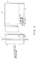
- a front 1 of the information recording/reproduction apparatus includes a card insertion portion 2 having an insertion opening 2a through which an optical card 30 serving as an optical recording medium is inserted in the direction of the arrow.
- the card insertion portion 2 has a hole 2b which is formed halfway in an insertion path of the optical card 30, and a first detector 3 is arranged in the hole 2b to detect that the optical card 30 has been inserted.
- the shutter 4 is always urged above by an urging means (not shown), and normally urged to close the insertion opening 2a as shown in Fig. 1.
- a solenoid (not shown) is driven to open the shutter 4.
- a drive roller 7 for carrying the inserted optical card to a table 10, described later, is arranged behind the shutter 4.
- a cleaning roller 5 is arranged above the drive roller 7 and urged toward the drive roller 7 by the urging means (not shown).
- the optical card 30 is thus inserted through the insertion opening 2a, then moved between the cleaning and drive rollers 5 and 7 through the shutter 4, and carried to the table 10 by rotation of a drive roller 7.
- An information recording surface of the optical card 30 is cleaned by the cleaning roller 5.
- the table 10, which serves to place the carried optical card thereon, is supported behind the rollers 5 and 7 by a supporting means (not shown) so that it can be moved in the directions of the arrows shown in Fig. 1.
- the table 10 is arranged just behind the rollers 5 and 7, as shown in Fig. 1, when the optical card 30 is charged on the table 10 and discharged from the table 10.
- a second detector 9 capable of detecting that the optical card 30 is charged on the table 10.
- the second detector 9 is not necessarily essential to the present invention.
- the table 10 includes a lower plate urged above, and a holding member 13 arranged in parallel with the lower plate so as to have a space virtually equal to the thickness of the optical card.
- the optical card is placed on the lower plate of the table 10, and urged above to bring one end of the optical card into contact with the holding member 13.
- the optical card 30 placed on the table 10 is indicated by the dotted line.
- a press roller 20 and a drive roller 22 are arranged away from the top and the underside of the holding member 13 at the leading edge, respectively.
- a hole 13a is formed in the holding member 13 so that these rollers 20 and 22 can be made close to each other.
- a hole (not shown) for the drive roller 22 is formed in the lower plate on which the optical card is placed.
- a fixed plate 24 is connected to the press roller 20, and a hole 24a is formed in the fixed plate 24 so that a lock pin 11 formed on the holding member 13 can be engaged with the fixed plate 24.
- Fig. 1 shows the table 10 which is unlocked.
- a third detector 12 is arranged at the rear edge of the table 10 to detect whether the optical card is normally placed on the table 10. Either a mechanical sensor or an optical sensor can be used for the detectors 3, 9 and 12.
- the optical card is carried by the drive rollers 7 and 22 and, when it is normally placed on the table 10, the press roller 20 and drive roller 22 are separated from each other, with the result that the table 10 is unlocked.
- the table 10 on which the optical card is placed is then moved in the directions of the arrow in Fig. 1 by a drive mechanism (not shown).
- An optical head 70 is supported above the table 10 and can be moved in a direction perpendicular to the surface of paper.
- the optical head 70 includes an LD 71 for actually generating recording power and a PD 72 for monitoring an amount of the recording power generated from the LD 71.
- the optical head 70 is driven in the direction perpendicular to the surface of paper at the same time when the table 10 on which the optical card is placed is moved in the directions of the arrow, the tracks on the optical card are scanned with a laser beam 71a so that record/reproduce of information is performed.
- the optical head 70 is fixed and the optical card place on the table is moved in the right and left directions in Fig. 1.
- the table 10 on which the optical card is placed is fixed and the optical head 70 is moved in the right and left directions relative to the optical card.
- the outputs of the detectors 3, 9 and 12 are connected to the input of a controller circuit (CPU) 50.
- the CPU 50 includes a time setting section 52, and a recording power controller 51 and a shutter/roller drive mechanism controller 53 both of which are supplied with commands from the time setting section 52.
- the time setting section 52 is supplied with detection signals from the detectors 3, 9 and 12, and then transmits timing signals to the recording power controller 51 at different timings in response to the detections signals. If the detector 9 is eliminated from this apparatus, the time setting section 52 detects a detection signal supplied from the detector 3 and then transmits a timing signal to the recording power controller 51 at a timing which is delayed by a predetermined period of time by a timer.
- a shutter/roller drive mechanism 55 for driving the shutter 4, drive rollers 7 and 22, and press roller 20 is controlled by a control signal from the controller 53 in response to the command output from the timer setting section 52.
- the recording power controller 51 is connected to a memory 54 in which a predetermined amount of laser beam emitted under recording power is stored. A corrected value of the laser driving current corresponds to the recording power, which will be described later, is also stored in the memory 54.
- a D/A converter 56 and an LD drive circuit 57 for driving the LD 71 included in the optical head 70, are connected to an output of the recording power controller 51.
- An amount of light output from the LD 71 is monitored by the PD 72 included in the optical head 70, and an output of the PD 72 is connected to an input of the recording power controller 51 through an A/D converter 58.
- the first detector 3 detects that the leading edge of the optical card 30 has reached a detection position of the detector 3 and outputs a detection signal.
- the detection signal is supplied to the shutter/roller drive mechanism controller 53 through the time setting section 52.
- a control signal of the controller 53 is input to the shutter/roller drive mechanism 55 so that the shutter 4 is opened and the drive rollers 7 and 22 are driven.
- the controller 53 can be so constituted as to supply the control signal to the drive mechanism 55 in order that the shutter 4 and drive rollers 7 and 22 are simultaneously driven in response to the detection signal of the first detector 3, or in order that they are driven in sequence at regular intervals.
- the optical card 30 is therefore carried toward the table 10.
- the recording power controller 51 In response to the detection signal supplied from the detector 3 to the time setting section 52, the recording power controller 51 is supplied with a signal indicating that the optical card 30 starts to be inserted into the insertion opening. The recording power controller 51 thus starts to emit a laser beam under recording power and correct the recording power. This correcting operation is usually completed before the carried optical card is detected by the second detector 9 and a timing signal is input to the recording power controller 51. If the second detector 9 is eliminated from this apparatus, the correcting operation is completed before a timing signal, which is transmitted from the time setting section 52 after a predetermined period of time after the detection signal of the first detector 3 is detected, is input to the recording power controller 51.
- a detection signal is input from the first detector 3 to the time setting section 52, a signal representing that the optical card starts to be inserted, is supplied to the recording power controller 51.
- the recording power controller 51 reads, from the memory 54, a predetermined value A of drive current required for emitting a laser beam from the LD 71 under recording power (step S1).
- the LD 71 emits the laser beam by the drive current A (step S2).
- the correcting operation of an amount of the laser beam emitted from the LD 71 is started (step S3). This correcting operation continues until the second detector 9 detects the optical card (step S4).
- the amount of the laser beam emitted from the LD 71 is monitored by the PD 72, and fed back to the recording power controller 51 through the A/D converter 58.
- the drive current is corrected to positive electricity which corresponds to just step value of A+ (steps S5 and S6).
- the drive current is corrected to negative electricity which corresponds to just step value of A- (steps S7 and S8).
- This correcting operation is repeated until the amount of the laser beam coincides with the target value. The more the amount of correction, the more the time required for the correcting operation.
- step S10 A value B of drive current required when the correcting operation is completed, is detected, and a value of B - A is stored in the memory 54 as a corrected value (step S10).
- the correcting operation is completed before the second detector detects the optical card. If time is required for the correcting operation, which is a considerably rare case, error processing is performed (step S12). This error processing is, for example, to supply an error status to a host computer and to display an error on a liquid crystal display.
- the optical card Since the leading edge of the optical card is carried to the initial light beam collecting position, the optical card may be damaged by the laser beam 71a emitted under recording power. To prevent the damage of the optical card, the power of the LD 71 is lowered to the reproduction power, and a laser beam is emitted (step S11). Needless to say, the power of the LD 71 can be off. The correcting operation is then completed.
- the corrected value stored in the memory 54 is added to the value A to cause the LD 71 emitting a laser beam. This adding operation is carried out in the recording power controller 51.
- the correcting operation is usually completed after the optical card 30 is inserted into the insertion opening 2a and before the second detector 9 detects the optical card. For this reason, under the recording power, the laser beam is emitted to the end of the table on which the optical card is not placed, which does not damage the optical card.
- the detection signal is supplied to the controller 53 through the time setting section 52.
- the control signal of the controller 53 is input to the shutter/roller drive mechanism 55. Therefore, the drive rollers 7 and 22 are stopped, the shutter 4 is closed, and the drive roller 22 and press roller 20 are separated from each other. Since the press roller 20 is separated from the drive roller 22, the locked state of the table 10 is released.
- the table 10 is reciprocated by a predetermined distance in the directions of the arrow shown in Fig. 1. Simultaneously, the optical head is also reciprocated in the direction perpendicular to the surface of paper. While the table 10 and optical head 70 are moving relative to each other, the optical head 70 emits a laser beam to scan the tracks of the optical card, thereby performing a recording or a reproducing or a reproducing operation or the like.
- the flowchart of Fig. 3 shows a case where the correcting operation is completed before the detection signal is issued from the second detector 9.
- a step of "starting a timer in the time setting section” is added between the steps S2 and S3.
- the count value of the timer corresponds to time required until the leading edge of the optical card reaches the initial light beam collecting position of the light beam 71a after the optical card is carried from the position of the detector 3.
- the step S4 is replaced with a step of "detecting whether the count value of the timer is a predetermined value ?".
- the second detector is arranged at the end of the table 10 in the apparatus shown in Fig. 1.
- the present invention is not limited to the position of the second detector.
- the correcting operation has only to be performed after the optical card is inserted into the insertion opening 2a and before it is carried to the initial laser beam collecting position. Therefore, as indicated by the dotted line in Fig. 1, a detector 9a can be arranged directly before the initial light beam collecting position to perform a collecting operation before a detection signal of the detector 9a is detected.
- the power of a laser beam emitted from the optical head to the optical card while information is being recorded is corrected to have a target value after the optical card is inserted and before it is carried to the initial laser beam collecting position. It is therefore possible to control the output of the laser beam for a short period of time, without causing the optical card to be damaged.
- the present invention has been described in a specific manner.
- the present invention is not limited to the above embodiment, but various changes and modifications can be made.
- the positions of the first and second detectors, and the method of detecting the optical card can be changed.
- the present invention can be applied to an information recording/reproduction apparatus using an optical disk.
Landscapes
- Physics & Mathematics (AREA)
- Optics & Photonics (AREA)
- General Physics & Mathematics (AREA)
- Engineering & Computer Science (AREA)
- Theoretical Computer Science (AREA)
- Optical Recording Or Reproduction (AREA)
Applications Claiming Priority (2)
| Application Number | Priority Date | Filing Date | Title |
|---|---|---|---|
| JP9754191 | 1991-04-26 | ||
| JP97541/91 | 1991-04-26 |
Publications (2)
| Publication Number | Publication Date |
|---|---|
| EP0510651A1 true EP0510651A1 (fr) | 1992-10-28 |
| EP0510651B1 EP0510651B1 (fr) | 1998-01-07 |
Family
ID=14195106
Family Applications (1)
| Application Number | Title | Priority Date | Filing Date |
|---|---|---|---|
| EP92106969A Expired - Lifetime EP0510651B1 (fr) | 1991-04-26 | 1992-04-23 | Appareil d'enregistrement/reproduction d'information |
Country Status (3)
| Country | Link |
|---|---|
| US (1) | US5274621A (fr) |
| EP (1) | EP0510651B1 (fr) |
| DE (1) | DE69223842T2 (fr) |
Cited By (1)
| Publication number | Priority date | Publication date | Assignee | Title |
|---|---|---|---|---|
| EP0594046A3 (fr) * | 1992-10-21 | 1995-02-22 | Blaupunkt Werke Gmbh | Appareil pour support d'enregistrement optique en forme de disque. |
Families Citing this family (4)
| Publication number | Priority date | Publication date | Assignee | Title |
|---|---|---|---|---|
| JPH0668588A (ja) * | 1992-08-19 | 1994-03-11 | Olympus Optical Co Ltd | 可換媒体記録再生装置 |
| JP3477770B2 (ja) * | 1992-12-16 | 2003-12-10 | 松下電器産業株式会社 | レーザパワー制御装置及び制御方法 |
| JPH06251559A (ja) * | 1993-02-26 | 1994-09-09 | Canon Inc | 光カード情報記録再生装置 |
| JP6647888B2 (ja) * | 2016-01-29 | 2020-02-14 | ビアメカニクス株式会社 | レーザ加工方法及びレーザ加工装置 |
Citations (4)
| Publication number | Priority date | Publication date | Assignee | Title |
|---|---|---|---|---|
| US4751394A (en) * | 1985-09-06 | 1988-06-14 | Canon Kabushiki Kaisha | Apparatus for recording and/or reproducing information using a card-like recording medium |
| US4825059A (en) * | 1985-10-25 | 1989-04-25 | Canon Kabushiki Kaisha | Apparatus for recording and reproducing information |
| US4937684A (en) * | 1985-10-16 | 1990-06-26 | Canon Kabushiki Kaisha | Information recording-reproducing apparatus |
| EP0478329A1 (fr) * | 1990-09-28 | 1992-04-01 | International Business Machines Corporation | Calibrage d'un faisceau lumineux dans un système de mémorisation de données optiques sur l'insertion d'un membre de mémorisation |
Family Cites Families (8)
| Publication number | Priority date | Publication date | Assignee | Title |
|---|---|---|---|---|
| JPS5840878A (ja) * | 1981-09-04 | 1983-03-09 | Hitachi Ltd | ディジタル光ディスク用半導体レーザの駆動装置 |
| FR2546325B1 (fr) * | 1983-05-20 | 1988-07-08 | Thomson Csf | Procede et dispositif de calibration de la puissance optique appliquee a un disque optique pour l'enregistrement de donnees |
| DE3541002A1 (de) * | 1984-11-20 | 1986-05-28 | Olympus Optical Co., Ltd., Tokio/Tokyo | Optisches informationsaufnahme- und -wiedergabespeichersystem |
| DE3546718C2 (fr) * | 1984-12-29 | 1990-06-28 | Canon K.K., Tokio/Tokyo, Jp | |
| JPS61253651A (ja) * | 1985-05-07 | 1986-11-11 | Hitachi Ltd | 光デイスク装置における記録パワ−検出方式 |
| JPH0668845B2 (ja) * | 1988-12-07 | 1994-08-31 | シャープ株式会社 | 光ディスク装置 |
| JPH03122835A (ja) * | 1989-10-05 | 1991-05-24 | Olympus Optical Co Ltd | 情報記録再生方法 |
| US5192858A (en) * | 1991-04-18 | 1993-03-09 | Olympus Optical Co., Ltd. | Optical card scanning apparatus |
-
1992
- 1992-04-20 US US07/871,239 patent/US5274621A/en not_active Expired - Fee Related
- 1992-04-23 DE DE69223842T patent/DE69223842T2/de not_active Expired - Fee Related
- 1992-04-23 EP EP92106969A patent/EP0510651B1/fr not_active Expired - Lifetime
Patent Citations (4)
| Publication number | Priority date | Publication date | Assignee | Title |
|---|---|---|---|---|
| US4751394A (en) * | 1985-09-06 | 1988-06-14 | Canon Kabushiki Kaisha | Apparatus for recording and/or reproducing information using a card-like recording medium |
| US4937684A (en) * | 1985-10-16 | 1990-06-26 | Canon Kabushiki Kaisha | Information recording-reproducing apparatus |
| US4825059A (en) * | 1985-10-25 | 1989-04-25 | Canon Kabushiki Kaisha | Apparatus for recording and reproducing information |
| EP0478329A1 (fr) * | 1990-09-28 | 1992-04-01 | International Business Machines Corporation | Calibrage d'un faisceau lumineux dans un système de mémorisation de données optiques sur l'insertion d'un membre de mémorisation |
Cited By (1)
| Publication number | Priority date | Publication date | Assignee | Title |
|---|---|---|---|---|
| EP0594046A3 (fr) * | 1992-10-21 | 1995-02-22 | Blaupunkt Werke Gmbh | Appareil pour support d'enregistrement optique en forme de disque. |
Also Published As
| Publication number | Publication date |
|---|---|
| DE69223842D1 (de) | 1998-02-12 |
| EP0510651B1 (fr) | 1998-01-07 |
| US5274621A (en) | 1993-12-28 |
| DE69223842T2 (de) | 1998-09-10 |
Similar Documents
| Publication | Publication Date | Title |
|---|---|---|
| US4829168A (en) | Optical memory card | |
| US5231615A (en) | Carriage fixing apparatus and disk driver having such carriage fixing apparatus | |
| US4135086A (en) | Automatic record player of linear tracking pickup arm type | |
| US4733314A (en) | Disc unit including automatic ejection upon misinsertion detection | |
| EP0395115B1 (fr) | Système d'enregistrement d'information | |
| US5274621A (en) | Information recording/reproduction apparatus | |
| JPS6257085A (ja) | 情報記録再生装置 | |
| EP0646910A1 (fr) | Dispositif d'emmagasinage optique | |
| JPH1139659A (ja) | 光ディスク装置 | |
| EP0364213B1 (fr) | Procédé et dispositif pour entraîner la source de lumière par une valeur de courant mémorisée et pour fournir des informations | |
| EP0343982B1 (fr) | Appareil pour enregistrer et/ou reproduire des informations | |
| JPH02156427A (ja) | 光ディスク装置 | |
| CN100386810C (zh) | 盘片检测装置 | |
| EP0257594B1 (fr) | Système d'enregistrement de données à inscription unique pour milieu optique | |
| US4989194A (en) | Optical information processing method of driving auto-focusing and/or auto-tracking means in accordance with a stored servo signal when irradiation of a record medium with light beam is stopped, and apparatus therefor | |
| JPH05114156A (ja) | 情報記録再生装置 | |
| JP2002136188A (ja) | 駆動装置 | |
| EP0694920A2 (fr) | Cartouche de protection pour disque et appareil à disque capable d'utiliser cette cartouche | |
| JP2754065B2 (ja) | 光方式記録再生装置の記録方法 | |
| EP0361935A2 (fr) | Appareil de traitement d'information comprenant des moyens de production de signal représentant la position relative entre la tête et le milieu | |
| JPH056614A (ja) | 光カード記録再生装置 | |
| KR940011090B1 (ko) | 광디스크 드라이브 및 그 제어 방법 | |
| JP2801667B2 (ja) | 光ディスク装置 | |
| JP2788297B2 (ja) | 光ディスク装置 | |
| JPH04141836A (ja) | 光学的情報記録再生装置 |
Legal Events
| Date | Code | Title | Description |
|---|---|---|---|
| PUAI | Public reference made under article 153(3) epc to a published international application that has entered the european phase |
Free format text: ORIGINAL CODE: 0009012 |
|
| 17P | Request for examination filed |
Effective date: 19920519 |
|
| AK | Designated contracting states |
Kind code of ref document: A1 Designated state(s): DE GB IT |
|
| 17Q | First examination report despatched |
Effective date: 19951006 |
|
| GRAG | Despatch of communication of intention to grant |
Free format text: ORIGINAL CODE: EPIDOS AGRA |
|
| GRAG | Despatch of communication of intention to grant |
Free format text: ORIGINAL CODE: EPIDOS AGRA |
|
| GRAH | Despatch of communication of intention to grant a patent |
Free format text: ORIGINAL CODE: EPIDOS IGRA |
|
| GRAH | Despatch of communication of intention to grant a patent |
Free format text: ORIGINAL CODE: EPIDOS IGRA |
|
| GRAA | (expected) grant |
Free format text: ORIGINAL CODE: 0009210 |
|
| AK | Designated contracting states |
Kind code of ref document: B1 Designated state(s): DE GB IT |
|
| REF | Corresponds to: |
Ref document number: 69223842 Country of ref document: DE Date of ref document: 19980212 |
|
| ITF | It: translation for a ep patent filed | ||
| PLBE | No opposition filed within time limit |
Free format text: ORIGINAL CODE: 0009261 |
|
| STAA | Information on the status of an ep patent application or granted ep patent |
Free format text: STATUS: NO OPPOSITION FILED WITHIN TIME LIMIT |
|
| 26N | No opposition filed | ||
| PGFP | Annual fee paid to national office [announced via postgrant information from national office to epo] |
Ref country code: GB Payment date: 20000419 Year of fee payment: 9 |
|
| PGFP | Annual fee paid to national office [announced via postgrant information from national office to epo] |
Ref country code: DE Payment date: 20000427 Year of fee payment: 9 |
|
| PG25 | Lapsed in a contracting state [announced via postgrant information from national office to epo] |
Ref country code: GB Free format text: LAPSE BECAUSE OF NON-PAYMENT OF DUE FEES Effective date: 20010423 |
|
| GBPC | Gb: european patent ceased through non-payment of renewal fee |
Effective date: 20010423 |
|
| PG25 | Lapsed in a contracting state [announced via postgrant information from national office to epo] |
Ref country code: DE Free format text: LAPSE BECAUSE OF NON-PAYMENT OF DUE FEES Effective date: 20020201 |
|
| PG25 | Lapsed in a contracting state [announced via postgrant information from national office to epo] |
Ref country code: IT Free format text: LAPSE BECAUSE OF NON-PAYMENT OF DUE FEES;WARNING: LAPSES OF ITALIAN PATENTS WITH EFFECTIVE DATE BEFORE 2007 MAY HAVE OCCURRED AT ANY TIME BEFORE 2007. THE CORRECT EFFECTIVE DATE MAY BE DIFFERENT FROM THE ONE RECORDED. Effective date: 20050423 |