EP0510973A1 - Dispositif de traitement de signal de télévision - Google Patents
Dispositif de traitement de signal de télévision Download PDFInfo
- Publication number
- EP0510973A1 EP0510973A1 EP92303661A EP92303661A EP0510973A1 EP 0510973 A1 EP0510973 A1 EP 0510973A1 EP 92303661 A EP92303661 A EP 92303661A EP 92303661 A EP92303661 A EP 92303661A EP 0510973 A1 EP0510973 A1 EP 0510973A1
- Authority
- EP
- European Patent Office
- Prior art keywords
- signal
- processing apparatus
- offset
- television
- signal processing
- Prior art date
- Legal status (The legal status is an assumption and is not a legal conclusion. Google has not performed a legal analysis and makes no representation as to the accuracy of the status listed.)
- Withdrawn
Links
Images




Classifications
-
- H—ELECTRICITY
- H04—ELECTRIC COMMUNICATION TECHNIQUE
- H04N—PICTORIAL COMMUNICATION, e.g. TELEVISION
- H04N7/00—Television systems
- H04N7/01—Conversion of standards, e.g. involving analogue television standards or digital television standards processed at pixel level
- H04N7/0117—Conversion of standards, e.g. involving analogue television standards or digital television standards processed at pixel level involving conversion of the spatial resolution of the incoming video signal
- H04N7/0122—Conversion of standards, e.g. involving analogue television standards or digital television standards processed at pixel level involving conversion of the spatial resolution of the incoming video signal the input and the output signals having different aspect ratios
-
- H—ELECTRICITY
- H04—ELECTRIC COMMUNICATION TECHNIQUE
- H04N—PICTORIAL COMMUNICATION, e.g. TELEVISION
- H04N7/00—Television systems
- H04N7/007—Systems with supplementary picture signal insertion during a portion of the active part of a television signal, e.g. during top and bottom lines in a HDTV letter-box system
-
- H—ELECTRICITY
- H04—ELECTRIC COMMUNICATION TECHNIQUE
- H04N—PICTORIAL COMMUNICATION, e.g. TELEVISION
- H04N5/00—Details of television systems
- H04N5/14—Picture signal circuitry for video frequency region
- H04N5/16—Circuitry for reinsertion of DC and slowly varying components of signal; Circuitry for preservation of black or white level
- H04N5/18—Circuitry for reinsertion of DC and slowly varying components of signal; Circuitry for preservation of black or white level by means of "clamp" circuit operated by switching circuit
Definitions
- the present invention relates to a television signal processing apparatus for multiplexing and transmitting additional information by time-division multiplexing the additional information with an existing television broadcast signal, within the same transmission band of the existing television broadcast signal.
- the existing television broadcast conforms to the NTSC (National Television System Committee) system in the specifications of 525 scanning lines, 2:1 interlace scanning, 4.2 MHz luminance signal horizontal band width, and 4:3 aspect ratio (horizontal to vertical ratio of screen).
- NTSC National Television System Committee
- Recently a television signal processing method which is compatible with the existing television broadcast and is capable of receiving an image of aspect ratio of 16:9 at the receiving side has been proposed.
- Fig. 8 shows an example of transmission side processing apparatus of the television signal processing method which is compatible with the existing television broadcast and is capable of receiving an image of an aspect ratio of 16:9 at the receiving side.
- numeral 41 is a signal source
- 42 is a distributor
- 43 is a vertical direction compressor
- 44 and 45 are selectors
- 46 is an additional information converter
- 47 is a set-up adder
- 48 is a blanking interval signal generator
- 49 is a transmitter
- 50 is an antenna.
- a signal from the video signal source 41 of 480 effective scanning lines and 16:9 aspect ratio is distributed into the vertical direction compressor 43 and additional information converter 46 by the distributor 42.
- the vertical direction compressor 43 in order to realize the aspect ratio of 16:9 of an oblong screen, the scanning lines are compressed from 480 to 360.
- the additional information converter 46 in order to settle the vertical high frequency components and horizontal high frequency components within the transmission capacity, band limitation, vertical direction compression, and frequency conversion are conducted.
- the output of the additional information converter 46 is entered in the set-up adder 47.
- the additional information is provided with a set-up (DC potential), and is disposed in the portion of the remaining 120 lines of the 480 scanning lines compressed to 360 (60 lines each in top and bottom, hereinafter called top and bottom bars).
- the resultant additional Information signal is changed over with the output of the vertical direction compressor 43 at constant intervals by the selector 44.
- the output of the selector 44 is fed into the selector 45.
- the blanking interval signal generator 48 sync signals in the horizontal and vertical blanking intervals, color burst signal, and pedestal level are generated.
- the output of the blanking interval signal generator 48 is changed over with the output of the selector 44 at constant intervals by the selector 45.
- the output of the selector 45 is sent through the transmitter 49 and antenna 50.
- the signal having the video signal of 16:9 aspect ratio located in the central 360 lines and additional information multiplexed in 120 lines in the top and bottom bars is transmitted.
- Fig. 9 shows an example of a receiving side processing apparatus for receiving the signal sent out from the transmission side processing apparatus shown in Fig. 8.
- Numeral 61 is an antenna
- 62 is a tuner
- 63 is a distributor
- 64 is a vertical direction expander
- 65 is an adder
- 66 is a set-up remover
- 67 is an additional information decoder
- 68 is a monitor.
- the signal demodulated to the base band is distributed into the vertical direction expander 64 and set-up remover 66 by the distributor 63.
- the vertical direction expander 64 the scanning lines are expanded from 360 lines to 480 lines.
- the set-up remover 66 the set-up applied at the transmission side in the top and bottom bars is removed.
- the output of the set-up remover 66 is fed to the additional information decoder 67.
- the additional information decoder 67 by band limitation, vertical direction expansion and frequency conversion, the additional information is restored to the original vertical high frequency components and horizontal high frequency components.
- the outputs of the vertical direction expander 64 and the additional information decoder 67 are summed up in the adder 65, and displayed in the monitor 68 of the 16:9 aspect ratio.
- the color signal multiplexing, separation processing and others relating to the NTSC are omitted because they are known arts (see "An experimental report for second generation EDTV (1)" by Urano et al., ITEJ Technical Report Vol. 14, No. 20, pp. 19-24, BCS90-22, March 1990).
- Fig. 10 shows the screen of displaying the reception of the output of the transmission side signal processing apparatus by the existing television receiver.
- the existing NTSC television broadcast of 525 scanning lines (the number of effective scanning lines for transmitting video signal is about 480)
- there is an overscan (the invisible portion concealed by the frame of the television receiver) in the vertical direction of about 8%, so that the actually displayed scanning lines are about 440.
- the output of the transmission side signal processing apparatus having video signal in the central 360 lines with additional information multiplexed in 120 lines in the top and bottom bars (the shaded area in Fig. 10) is received, about 80 lines of the top and bottom bars are displayed. It is the condition of the new broadcasting system that there is no interference or adverse effect if displayed by the existing television receiver, that is, the compatibility is guaranteed.
- Fig. 7 (a) An example of waveform in one horizontal scanning period of the top and bottom bars is shown in Fig. 7 (a).
- the signal indicated in period T1 is a horizontal sync signal
- T2 is a front porch
- T3 is a back porch
- T4 is a color burst signal
- T5 is an additional information
- A1 is the amplitude of the additional information
- A2 is the amplitude of the set-up level.
- the clamp pulse waveform is adjusted in the time axis with the waveform in Fig. 7 (a).
- the signal indicated in period T6 is a clamp pulse.
- the clamp circuit is used in order to reproduce the DC potential of the video signal.
- the clamp circuit by holding the DC potential of the signal portion gated by the clamp pulse, the DC potential of the entire video signal is reproduced.
- Clamping may be done in the period of sync signal or in the period of back porch.
- clamping is done in the back porch as shown in Figs. 7 (a) and 7 (b).
- the color burst signal is usually removed by band limitation so as not to adversely effect the clamping.
- the reference level of the DC potential generated by clamping is the pedestal level of the back porch period. This level is the black reference level of the video signal.
- the amplitude A1 of the additional information must be reduced as shown in Fig. 7 (a).
- the set-up level A2 is required.
- the level of the signal is always close to the black level, considering the negative modulation of television broadcasting, the average transmission power of the transmitter is increased.
- a television signal processing apparatus at the transmission side of the invention comprises means for converting a video signal having a larger aspect ratio than an aspect ratio 4:3 of an image determined in the standard of a transmission system into a first signal settling within an image frame specified in the standard, means for obtaining a second signal different from the converted first signal, means for disposing the second signal in other area than the image frame, means for adding an offset to a pedestal in a horizontal blanking interval in the other area than the image frame, and means for adding a set-up to the pedestal in an effective scanning period in the other area than the image frame.
- a television signal processing apparatus at the reception side of the invention comprises means for receiving a signal generated in the television signal processing apparatus at the transmission side, and removing from the received signal the offset and set-up of the pedestal in the portion in which the second signal is multiplexed, means for restoring the second signal, and means for converting the first signal.
- Fig. 1 is a block diagram at the transmission side for explaining the television signal processing apparatus of the invention.
- Numeral 1 is a signal source
- 2 is a distributor
- 3 is a vertical direction compressor
- 4 are selectors
- 6 is an additional information converter
- 7 is a set-up adder
- 8 is a blanking interval signal generator
- 9 is an offset generator
- 10 is an adder
- 11 is a transmitter
- 12 is an antenna.
- the signal from the video signal source 1 of 480 effective scanning lines and 16:9 aspect ratio is distributed into the vertical direction compressor 3 and additional information converter 6 by the distributor 2.
- the vertical direction compressor 3 in order to realize the aspect ratio of 16:9 of an oblong screen, the scanning lines are compressed from 480 to, for example, 360.
- the output of the vertical direction compressor 3 is fed into the selector 4.
- the additional information converter 6 in order to settle, for example, vertical high frequency components and horizontal high frequency components as additional information within the transmission capacity, band limitation, vertical direction compression and frequency conversion are carried out.
- the additional information may be only vertical high frequency components or only horizontal high frequency components, or both.
- the output of the additional information converter 6 is fed into the set-up adder 7.
- the additional information is provided with a set-up, and is disposed in the portions of the top and bottom bars.
- the selector 4 the output of the set-up adder 7 is selected in the period of top and bottom bars. The output of the selector 4 is fed into the selector 5.
- the offset generator 9 generates an offset which is a DC potential to be added to the pedestal in the back porch in the horizontal blanking interval in the period of top and bottom bars.
- the value of the offset is not required to be always constant in the period of top and bottom bars. For example, depending on the offset removal characteristic of the clamp circuit in the existing receiver, the value of the offset may be decreased as approaching the period of video transmission in other period than the top and bottom bars.
- the output of the offset generator 9 and the output of the blanking interval signal generator 8 are summed up in the adder 10.
- the output of the adder 10 is changed over with the output of the selector 4 at a specific intervals by the selector 5.
- the output of the selector 5 is transmitted through the transmitter 11 and antenna 12.
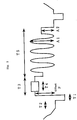
- FIG. 3 An example of signal waveform in one horizontal scanning period in the period of top and bottom bars is shown in Fig. 3.
- the signal indicated in period T1 is a horizontal sync signal
- T2 is a front porch
- T3 is a back porch
- T4 is a color burst signal
- T5 is an additional information
- A1 is the amplitude of the additional information
- A2 is the amplitude of the set-up
- P is the amplitude of the offset.
- the offset P is applied to the pedestal signal in the period of back porch T3.
- the amplitude A1 of the additional information may be extended without exceeding much the pedestal level or without adversely affecting the sync signal.
- the methods shown in Figs. 4 and 5 may be also possible.
- the offset P is applied from the period between the trailing edge of horizontal sync signal and leading edge of color burst.
- the offset P is applied from the leading edge of color burst.
- These methods are intended to adjust the level before and after the horizontal sync signal similarly to the conventional method so as not to adversely affect the integrating circuit or the like of the sync signal processing of the existing receiver.
- the information of offset P, set-up A2 and others may be transmitted by multiplexing, for example, in the vertical or horizontal blanking interval, overscan period or the like depending on the necessity.
- Fig. 11 is a block diagram showing an example of additional information converters 6 and 46 shown in Figs. 1 and 8.
- Numeral 101 is a vertical axis high pass filter
- 102 is a horizontal axis high pass filter
- 103 is a multiplex circuit.
- the image signal from the signal source is fed into the vertical axis high pass filter 101 and horizontal axis high pass filter 102, and only the necessary band components are extracted.
- the output of the vertical axis high pass filter 101 and the output of the horizontal axis high pass filter 102 are fed into the multiplex circuit 103, in which these signals undergo time axis compression, frequency conversion and the like so as to settle within the transmission band, and are outputted in the format of time division multiplex or frequency division multiplex.
- Fig. 2 shows an example of reception side processing apparatus for receiving the signal sent out from the transmission side processing apparatus shown in Fig. 1.
- Numeral 21 is an antenna
- 22 is a tuner
- 23 is a distributor
- 24 is a vertical direction expander
- 25 is an adder
- 26 is an offset remover
- 27 is a set-up remover
- 28 is an additional information decoder
- 29 is a monitor.
- the signal demodulated in the base band by the antenna 21 and tuner 22 is distributed into the vertical direction expander 24 and offset remover 26 by the distributor 23.
- the vertical direction expander 24 the scanning lines are expanded from 360 to 480.
- the offset remover 26 the offset applied to the pedestal at the transmission side as shown in Fig. 3 is removed.
- the clamp level is set so as not to distort the additional information when, for example, clamping the back porch pedestal, and when clamped, the reference potential is determined, so that the offset can be removed. That is, the clamp level is set corresponding to the applied amount of offset.
- the set-up applied at the transmission side in the parts of top and bottom bars is removed.
- the set-up is removed from the set-up information sent from the transmission side, or if the additional information is free from DC components, the set-up may be removed by a high pass filter or the like.
- the output of the set-up remover 27 is fed into the additional information decoder 28.
- the additional information decoder 28 by band limitation, vertical direction expansion and frequency conversion, the additional information is restored into the original vertical high frequency components or horizontal high frequency components.
- the outputs of the vertical direction expander 24 and additional information decoder 28 are summed up in the adder 25, and displayed on the monitor 29 with the aspect ratio of 16:9.
- the multiplexing of color signal relating to the NTSC, separation processing of luminance signal and chrominance signal and others are known arts and are hence omitted.
- Fig. 12 is a block diagram showing an example of internal configuration of the additional information decoders 28 and 67 in Figs. 2 and 9.
- Numeral 111 is a time axis expanding circuit
- 112 is a filter
- 113 is a frequency conversion circuit.
- the signal being transmitted by time division multiplexing and frequency division multiplexing at the transmission side is restored to the initial time length in the time axis expanding circuit 111, separated on the frequency axis in the filter 112, and returned to the signal of the original band in the frequency conversion circuit 113.
- Compression and expansion of the time axis may be done, for example, by varying writing clock and reading clock of a memory.
- Fig. 13 is a block diagram showing an example of internal configuration of the offset remover 26 in Fig. 2.
- Numeral 121 is a clamp circuit
- 122 is a clamp level converter.
- the output signal from the tuner or the like is fed into the clamp circuit 121, and is clamped by the clamp pulse, for example, as shown in Fig. 7 for reproduction of DC component.
- the clamp level converter 122 the clamp level is changed over so that the level may differ between the period of top and bottom bars and the period of transmission of the central image. This is intended to reproduce, without amplitude distortion, the additional information transmitted in the period of top and bottom bars.
- the different reference potentials are changed over by an analog switch or the like.
- the clamp circuit itself is a known art and is omitted herein.
- the original broadcasting system is the NTSC system
- the number of effective scanning lines is 480
- the number of scanning lines of the signal composed of vertical low frequency components is 360
- the additional information is composed of vertical high frequency components and horizontal high frequency components, but these are not limitative.
- the invention may be applied also to the PAL system or SECAM system.
- the additional information may be voice signal or the like. Or the additional information may be a signal processed in a format of digital signal.
- the additional information signal such as vertical high frequency component is multiplexed on the pedestal level in the portions of the top and bottom bars shown in Fig. 10, together with the offset and set-up as shown in Figs. 3, 4 and 5.
- the multiplexing amplitude was small considering that the additional information signal was disturbing when received by the existing receiver, but it is not necessary in this method. Therefore, a sufficient signal-to-noise (S/N) ratio of the additional information signal may be guaranteed.
- the offset in the multiplexed portions of the top and bottom bars is removed by clamping or the like, and the additional information is reproduced. That is, in the special-purpose receiver as shown in Fig. 2, by the reproduction of additional information less in deterioration of S/N ratio, an image of higher resolution with the aspect ratio of 16:9 can be received.
Landscapes
- Engineering & Computer Science (AREA)
- Multimedia (AREA)
- Signal Processing (AREA)
- Computer Graphics (AREA)
- Television Systems (AREA)
Applications Claiming Priority (1)
| Application Number | Priority Date | Filing Date | Title |
|---|---|---|---|
| JP3095809A JPH04326275A (ja) | 1991-04-25 | 1991-04-25 | テレビジョン信号処理方法と処理装置 |
Publications (1)
| Publication Number | Publication Date |
|---|---|
| EP0510973A1 true EP0510973A1 (fr) | 1992-10-28 |
Family
ID=14147756
Family Applications (1)
| Application Number | Title | Priority Date | Filing Date |
|---|---|---|---|
| EP92303661A Withdrawn EP0510973A1 (fr) | 1991-04-25 | 1992-04-23 | Dispositif de traitement de signal de télévision |
Country Status (2)
| Country | Link |
|---|---|
| EP (1) | EP0510973A1 (fr) |
| JP (1) | JPH04326275A (fr) |
Cited By (5)
| Publication number | Priority date | Publication date | Assignee | Title |
|---|---|---|---|---|
| GB2264418A (en) * | 1992-02-21 | 1993-08-25 | Gen Electric | Reduction of noise effects in image format conversion systems. |
| US5270817A (en) * | 1992-04-21 | 1993-12-14 | Matsushita Electric Industrial Co., Ltd. | Television signal processing apparatus for separating an auxiliary signal from a letterbox signal |
| EP0616469A3 (fr) * | 1993-03-15 | 1995-02-01 | Victor Company Of Japan | Système de traitement de signal de télévision. |
| EP0641126A3 (fr) * | 1993-08-24 | 1995-03-22 | Nippon Television Network Corporation | Appareil pour commander le niveau de transmission de signal additionel et transmission/réception de signal additionel dans système de télévision |
| GB2275586B (en) * | 1991-10-30 | 1995-07-19 | British Broadcasting Corp | Improvements in television systems |
Families Citing this family (1)
| Publication number | Priority date | Publication date | Assignee | Title |
|---|---|---|---|---|
| US5432557A (en) * | 1992-09-07 | 1995-07-11 | U.S. Philips Corporation | Extended television signal receiver |
Citations (3)
| Publication number | Priority date | Publication date | Assignee | Title |
|---|---|---|---|---|
| WO1990006655A1 (fr) * | 1988-12-07 | 1990-06-14 | Telefunken Fernseh Und Rundfunk Gmbh | Systeme de transmission de television compatible avec les normes classiques de television |
| US4961112A (en) * | 1988-10-22 | 1990-10-02 | Nippon Television Network Corporation | Television system |
| WO1990014732A1 (fr) * | 1989-05-18 | 1990-11-29 | Independent Broadcasting Authority | Transmission de donnees pendant la periode active de l'image |
-
1991
- 1991-04-25 JP JP3095809A patent/JPH04326275A/ja active Pending
-
1992
- 1992-04-23 EP EP92303661A patent/EP0510973A1/fr not_active Withdrawn
Patent Citations (3)
| Publication number | Priority date | Publication date | Assignee | Title |
|---|---|---|---|---|
| US4961112A (en) * | 1988-10-22 | 1990-10-02 | Nippon Television Network Corporation | Television system |
| WO1990006655A1 (fr) * | 1988-12-07 | 1990-06-14 | Telefunken Fernseh Und Rundfunk Gmbh | Systeme de transmission de television compatible avec les normes classiques de television |
| WO1990014732A1 (fr) * | 1989-05-18 | 1990-11-29 | Independent Broadcasting Authority | Transmission de donnees pendant la periode active de l'image |
Cited By (8)
| Publication number | Priority date | Publication date | Assignee | Title |
|---|---|---|---|---|
| GB2275586B (en) * | 1991-10-30 | 1995-07-19 | British Broadcasting Corp | Improvements in television systems |
| GB2264418A (en) * | 1992-02-21 | 1993-08-25 | Gen Electric | Reduction of noise effects in image format conversion systems. |
| US5384599A (en) * | 1992-02-21 | 1995-01-24 | General Electric Company | Television image format conversion system including noise reduction apparatus |
| GB2264418B (en) * | 1992-02-21 | 1995-07-26 | Gen Electric | Television image format conversion system |
| US5270817A (en) * | 1992-04-21 | 1993-12-14 | Matsushita Electric Industrial Co., Ltd. | Television signal processing apparatus for separating an auxiliary signal from a letterbox signal |
| EP0567304A3 (en) * | 1992-04-21 | 1994-05-25 | Matsushita Electric Industrial Co Ltd | Television signal processing apparatus |
| EP0616469A3 (fr) * | 1993-03-15 | 1995-02-01 | Victor Company Of Japan | Système de traitement de signal de télévision. |
| EP0641126A3 (fr) * | 1993-08-24 | 1995-03-22 | Nippon Television Network Corporation | Appareil pour commander le niveau de transmission de signal additionel et transmission/réception de signal additionel dans système de télévision |
Also Published As
| Publication number | Publication date |
|---|---|
| JPH04326275A (ja) | 1992-11-16 |
Similar Documents
| Publication | Publication Date | Title |
|---|---|---|
| US5132793A (en) | Television receiver compatible with both standard system television signal and high definition television signal | |
| US4551754A (en) | Compatible wide-screen color television system | |
| JP2625102B2 (ja) | Macテレビジョン信号の符号器、復号器、通信方法及びその装置 | |
| NZ201838A (en) | Reducing line scan artifacts in television display | |
| US4574300A (en) | High-definition color television transmission system | |
| JPS613585A (ja) | テレビジヨン伝送方式並びに送信及び受信装置 | |
| US5043805A (en) | TV signal transmission systems and methods | |
| EP0510973A1 (fr) | Dispositif de traitement de signal de télévision | |
| US4847676A (en) | Color television system | |
| US5111287A (en) | TV signal transmission systems and methods | |
| KR0142586B1 (ko) | 종래의 텔레비젼 시스템과 호환가능한 텔레비젼 전송 시스템 | |
| US4953009A (en) | Signal separator having function of subsampling digital composite video signal | |
| KR940011599B1 (ko) | 다중화신호 전송장치 및 다중화신호 수신장치 | |
| JPH07307904A (ja) | 2画面テレビジョン受像機 | |
| JP2525431B2 (ja) | Rgbマルチ端子入力対応型順次走査変換テレビジョン受像機 | |
| KR0158410B1 (ko) | 동기신호 분리시스템 | |
| JP2624782B2 (ja) | テレビジョン信号伝送方式,及び復調方式 | |
| KR100188220B1 (ko) | 고화질텔레비전의 동기절환시 자동디가우싱장치 | |
| JP2671850B2 (ja) | 第2世代クリアビジョン復号回路 | |
| JP2598549B2 (ja) | テレビジョン信号の伝送方式及びその再生装置 | |
| JPH08331520A (ja) | Edtvデコーダ装置 | |
| JPH05328251A (ja) | テレビジョン受像機 | |
| JPH0686310A (ja) | テレビジョン受像機 | |
| JPH06233265A (ja) | 複合映像信号多重化方法 | |
| JPH06217262A (ja) | テレビジョン回路 |
Legal Events
| Date | Code | Title | Description |
|---|---|---|---|
| PUAI | Public reference made under article 153(3) epc to a published international application that has entered the european phase |
Free format text: ORIGINAL CODE: 0009012 |
|
| AK | Designated contracting states |
Kind code of ref document: A1 Designated state(s): DE FR GB NL |
|
| STAA | Information on the status of an ep patent application or granted ep patent |
Free format text: STATUS: THE APPLICATION IS DEEMED TO BE WITHDRAWN |
|
| 18D | Application deemed to be withdrawn |
Effective date: 19930429 |