EP0511065A1 - Verfahren zum Dekompilieren zur Realisierung eines Graphs unter Anwendung eines Rechners - Google Patents
Verfahren zum Dekompilieren zur Realisierung eines Graphs unter Anwendung eines Rechners Download PDFInfo
- Publication number
- EP0511065A1 EP0511065A1 EP92401096A EP92401096A EP0511065A1 EP 0511065 A1 EP0511065 A1 EP 0511065A1 EP 92401096 A EP92401096 A EP 92401096A EP 92401096 A EP92401096 A EP 92401096A EP 0511065 A1 EP0511065 A1 EP 0511065A1
- Authority
- EP
- European Patent Office
- Prior art keywords
- branch
- node
- branche
- column
- depl
- Prior art date
- Legal status (The legal status is an assumption and is not a legal conclusion. Google has not performed a legal analysis and makes no representation as to the accuracy of the status listed.)
- Granted
Links
Images






Classifications
-
- G—PHYSICS
- G06—COMPUTING OR CALCULATING; COUNTING
- G06F—ELECTRIC DIGITAL DATA PROCESSING
- G06F3/00—Input arrangements for transferring data to be processed into a form capable of being handled by the computer; Output arrangements for transferring data from processing unit to output unit, e.g. interface arrangements
- G06F3/01—Input arrangements or combined input and output arrangements for interaction between user and computer
- G06F3/048—Interaction techniques based on graphical user interfaces [GUI]
- G06F3/0484—Interaction techniques based on graphical user interfaces [GUI] for the control of specific functions or operations, e.g. selecting or manipulating an object, an image or a displayed text element, setting a parameter value or selecting a range
- G06F3/04845—Interaction techniques based on graphical user interfaces [GUI] for the control of specific functions or operations, e.g. selecting or manipulating an object, an image or a displayed text element, setting a parameter value or selecting a range for image manipulation, e.g. dragging, rotation, expansion or change of colour
-
- G—PHYSICS
- G06—COMPUTING OR CALCULATING; COUNTING
- G06F—ELECTRIC DIGITAL DATA PROCESSING
- G06F30/00—Computer-aided design [CAD]
- G06F30/10—Geometric CAD
- G06F30/18—Network design, e.g. design based on topological or interconnect aspects of utility systems, piping, heating ventilation air conditioning [HVAC] or cabling
-
- G—PHYSICS
- G06—COMPUTING OR CALCULATING; COUNTING
- G06T—IMAGE DATA PROCESSING OR GENERATION, IN GENERAL
- G06T1/00—General purpose image data processing
Definitions
- the present description relates to a decompilation process for the production of graphs by means of a computer, in particular for the representation of a structured oriented graph.
- So-called "oriented” languages are used in many fields. These languages are languages developed for a particular application. This is the case, for example, of the LDS description and specification language, defined and standardized by the CCITT. This language is commonly used in the telecommunications field and its use tends to widen to any type of real-time application.
- a structured graph is a diagram made up of related elements.
- the decompilation process implemented by the decompiler performs the correspondence between the tree of the internal representation and the graphic representation of the diagram on the screen.
- a first consequence is the visual discomfort caused.
- the conventional methods consist in erasing the whole drawing and making it reappear on the screen with the correction.
- this operation causes a "flash" effect which disturbs visually and which would not occur if the diagram was made by hand (where in this case, only the useful part would be redrawn).
- the present invention aims to remedy these drawbacks.
- the invention as characterized in the claims, solves the problem of proposing a decompilation method which is incremental and which allows graphs to be produced by means of a computer entailing a minimum of redrawing just as could do an operator with an eraser and a pencil.
- the process according to the invention therefore has the desired visual comfort and a considerable improvement in response time.
- the present invention more particularly relates to a decompilation process for producing graphs by means of a computer, characterized in that it consists in defining and storing in memory elements used for the construction of graphs in tree form consisting of knots and branches.
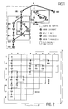
- a simple node is a node having a single outgoing arc, this node having one or more incoming arcs (for example Bl, Dl, Gl).
- a terminator node is a node without an outgoing arc, this node having one or more incoming arcs (for example Hl, D3, B3).
- a divergent node is a node having only outgoing arcs and such that there is no common node between the groups of paths generated (for example A).
- a group of paths is the set of paths starting with an arc leaving a divergent node.
- the group of paths starting with the arc A ⁇ Bl consists of three paths: (A, Bl, Cl, Dl, El, Fl, Gl, Hl) (A, Bl, Cl, D2, E2, F2, Gl, Hl) (A, Bl, Cl, D2, E3, F2, Gl, Hl)
- a group of paths is called a branch (notation A ⁇ Bl).
- a point of convergence can be a single node (for example Gl), a terminator node (for example D3) or a converging node.
- the different nodes introduced are the basis of structures which overlap one another. We distinguish mother structures, daughter structures and sister structures.
- a parent structure is a structure encompassing another structure.
- a child structure is a structure encompassed by another structure.
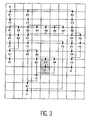
- FIG. 2 corresponds to the graphic representation on the screen of the graph of FIG. 1 in accordance with the invention.
- the structured oriented graph is represented in matrix form corresponding to a tiling of the screen.
- the tiling is obtained by cutting the screen into regular rectangular areas.
- the nodes of the graph are centered in a basic rectangle: the arcs are represented vertically, horizontally or both at the same time.
- the horizontal arrangements correspond to the branches emerging from the divergent knot or from a convergent knot (rectangles placed side by side).
- the vertical arrangements correspond to the nodes appearing on a branch (rectangles placed one below the other).
- a node is represented in a rectangular area composed of basic paving stones. This area is defined by its coordinates called row and column, by its width called x-node and its height called y-node.
- the divergent node has for dimension the size of the graph.
- a converging node has for dimension the size of the convergence subgraph.
- line (Cl) 3
- column (Cl) l
- x-node (Cl) 3
- y-node (Cl) 4.
- a branch is also represented in a rectangular area composed of basic paving stones. This area is defined by its coordinates called row and column, by its width called x-branch and its height called y-branch.
- line (A ⁇ B2) l
- column (A ⁇ B2) 4
- x-branch (A ⁇ B2) 3
- y-branch (A ⁇ B2) 3.
- the graphic representation defined above generates four forms of arcs.
- a horizontal arrow coming from the divergent node or from a convergent node is called a horizontal arrow.
- These arcs are characterized by:
- a small arrow is characterized by: his coordinates : arrival column, "column” finish line, "line”
- a link is characterized by: his coordinates : start column, “column” starting line, “line” its scope: its height, “y-size” its width, “x-size”
- links There are two types of links: horizontal links and vertical-horizontal links.
- a vertical-horizontal link is associated with paths that do not end with a terminator node.
- the arc C2 ⁇ D3 is composed of a vertical-horizontal link and a small arrow.
- the method makes it possible to minimize the redrawing in the event of modification.
- the method described below makes it possible to calculate the parts of the graph affected by a modification, that is to say in accordance with the invention the parts to be moved;
- the method allows, despite the complexity of the overlapping of structures and in particular of the convergence subgraphs, to modify the graph only locally.
- This method is capable of being implemented by any type of computer with which it is sought to produce and modify a structured oriented graph used in particular by the description and specification language LDS.
- the method consists in defining a data structure which describes any state graph in the form of a tree structure (fig. 1).
- This structure is saved in memory in the computer or microcomputer (not shown). This is the internal representation of the graph. The method then consists in establishing a correspondence between this tree structure and an external representation.
- This exemplary representation is the image of the tree obtained on the screen of the microcomputer.
- this table contains the various nodes (start., Stop, state, task, decision) corresponding to the nodes of the tree, the links between them and their location defined with respect to a matrix division of the screen.
- Each LDS state (tree divergent node) is centered in a screen block.
- the paving results from a division into regular zones (rectangular zones for example).
- the arcs are represented vertically and / or horizontally and belong to a row or to a column of the screen.
- the correspondence table also includes the complete identification of the elements. This identification is done by a description on the nature of the element, the column, the line, the horizontal and vertical sizes, the type and size of the arrows, the link if it is a decision branch ( converging node).
- a link is described by its coordinates (starting line and column) as well as by its extent in the vertical and horizontal direction (width and height).
- the operator has an input / output device, for example "a mouse” and realizes by pointing on the screen the choice of the operation (destruction) and the element to be destroyed.
- an input / output device for example "a mouse” and realizes by pointing on the screen the choice of the operation (destruction) and the element to be destroyed.
- the determination of the encompassing structure consists in determining the branch structure which contains the branch or the node to be destroyed and its parent structure.
- the operations for determining the encompassing structure and for determining the offsets are iterative and stop when the displacements to be carried out are zero and at the latest when one has ascended to the root of the tree (i.e. until divergent knot).
- the destruction of an element of the graph therefore consists in carrying out steps of displacements from the right to the left (called displacements on the left or horizontal displacements) and stages of displacements from bottom to top (called displacements at the top or vertical displacements).
- the branch structure is the branch on which the parent structure of the previous step is located, which becomes the daughter structure.
- the modification stops when the horizontal and vertical displacements are zero, or when the parent structure is the divergent node.
- the branch structure is the branch G3 ⁇ H3 and the parent structure is the converging node G3.
- the branch structure is the branch F2 ⁇ G3 and the parent structure is the converging node F2.
- the branch structure is the branch E3 ⁇ F2 and the parent structure is the converging node E3.
- the branch structure is the branch A ⁇ B2 and the parent structure is the divergent node A.
- the modifications are made according to the modifications at the preceding stage.
- the horizontal displacement acts on the region on the right.
- the vertical displacement acts on the region below.
- the regions on the right and at the bottom are defined by their coordinates (column and line of the block at the top and left of the region), their height and their width.
- the horizontal displacement is named x-depl.
- the vertical displacement is named y-depl.
- Processing links This case concerns converging nodes.
- the links are calculated at each stage.
- the bi branch has no link:
- the last node of the bi branch is a terminator and there are no links on the right (all the branches to the right of bi end with a terminator node).
- the bi branch has a horizontal link:
- the last node of the bi branch is a terminator and there is at least one link on the right (at least one of the branches to the right of bi does not end in a terminator).
- the bi branch has a vertical-horizontal link:
- the method firstly comprises an initialization step consisting of:
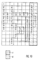
- FIG. 4 graphically shows the different steps of the process when updating the diagram. Regions I are moved during the first stage, regions II during the second stage, regions III during the third stage and regions IV during the fourth stage.
- Step l region I, figure 4.
- Step 2 region II, figure 4.
- Step 3 region III, figure 4.
- Step 4 region IV, figure 4.
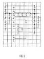
- FIG. 6 shows the node to be destroyed H3
- FIG. 7 gives the different steps for updating the diagrams
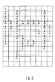
- FIG. 8 gives the result obtained.
- Region I is moved during the first stage, region II during the second stage, region III during the third stage and region IV during the fourth stage.
- Step l region 1, figure 7):
- Step 2 region II, figure 7):
- Step 3 (region III, figure 7)
- Step 4 region IV, figure 7)
- the insertion consists in carrying out, step by step, movements from the left to the right (called displacements to the right or horizontal displacements) and displacements from top to bottom (called displacements downwards or vertical displacements).
- the movements go in the opposite direction. Movements are made from the higher-level bounding structure affected by the modification, to the structure which will contain the element to be inserted.
- the insertion operation therefore comprises two distinct phases:
- the first phase consists of a calculation of the displacements and the regions to be displaced and a calculation of the modifications of the branch structures and of the mother structures.
- the second phase consists of descending into the structures, carrying out the displacements and then carrying out the insertion.
- Figure 9 shows a diagram in which we insert a branch E3 ⁇ Z0.
- the branch structure is the branch on which the mother structure of the previous step is located, which then becomes the daughter structure.
- the branch structure is the branch E3 ⁇ Z0 and the mother structure is the converging node E3.
- the branch structure is the branch A ⁇ B2 and the parent structure is the divergent node A.
- the daughter structure is the convergent node E3.
- x-size (branch on the right) x-size (branch on the right) + x-depl.
- the bi branch has no link:
- the last node of the bi branch is a terminator and there is no link on the right (all bi branches end with a terminator node).
- the bi branch has a horizontal link:
- the last node of the bi branch is a terminator and there is at least one link on the right (at least one of the branches to the right of bi does not end in a terminator). In this case, calculate the starting coordinates of the link and its extent.
- x-size x-branch (left branch (bi + l)) if there is a branch on the left otherwise 0
- y-size 0
- the bi branch has a vertical-horizontal link:
- the method firstly comprises an initialization step consisting in:
- Step l region I, figure l0
- Step 2 region II, figure 10.
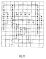
- Step l region I, figure l3
- Step 2 region II, figure l3
- Step 3 region III, figure l3
- Step 4 region IV, figure l3
Landscapes
- Engineering & Computer Science (AREA)
- Theoretical Computer Science (AREA)
- Physics & Mathematics (AREA)
- General Physics & Mathematics (AREA)
- General Engineering & Computer Science (AREA)
- Geometry (AREA)
- Evolutionary Computation (AREA)
- Human Computer Interaction (AREA)
- Pure & Applied Mathematics (AREA)
- Computer Hardware Design (AREA)
- Mathematical Analysis (AREA)
- Computational Mathematics (AREA)
- Computer Networks & Wireless Communication (AREA)
- Mathematical Optimization (AREA)
- Data Exchanges In Wide-Area Networks (AREA)
- Image Generation (AREA)
- Processing Or Creating Images (AREA)
- Design And Manufacture Of Integrated Circuits (AREA)
- Stored Programmes (AREA)
- Information Retrieval, Db Structures And Fs Structures Therefor (AREA)
Applications Claiming Priority (2)
| Application Number | Priority Date | Filing Date | Title |
|---|---|---|---|
| FR9104922A FR2675606B1 (fr) | 1991-04-22 | 1991-04-22 | Procede de decompilation pour la realisation de graphes au moyen d'un ordinateur. |
| FR9104922 | 1991-04-22 |
Publications (2)
| Publication Number | Publication Date |
|---|---|
| EP0511065A1 true EP0511065A1 (de) | 1992-10-28 |
| EP0511065B1 EP0511065B1 (de) | 1997-10-08 |
Family
ID=9412108
Family Applications (1)
| Application Number | Title | Priority Date | Filing Date |
|---|---|---|---|
| EP92401096A Expired - Lifetime EP0511065B1 (de) | 1991-04-22 | 1992-04-17 | Verfahren zum Dekompilieren zur Realisierung eines Graphs unter Anwendung eines Rechners |
Country Status (5)
| Country | Link |
|---|---|
| US (1) | US5278951A (de) |
| EP (1) | EP0511065B1 (de) |
| JP (1) | JPH05158676A (de) |
| DE (1) | DE69222562T2 (de) |
| FR (1) | FR2675606B1 (de) |
Cited By (3)
| Publication number | Priority date | Publication date | Assignee | Title |
|---|---|---|---|---|
| EP0603425A1 (de) * | 1992-12-22 | 1994-06-29 | International Business Machines Corporation | Darstellung einer N-fach-Baumstruktur |
| EP0702292A3 (de) * | 1994-09-19 | 1996-07-03 | At & T Corp | Grafische Umgebung für Systemkonstruktion |
| CN106003052A (zh) * | 2016-07-29 | 2016-10-12 | 哈尔滨工大服务机器人有限公司 | 一种机器人视觉导航地图的创建方法 |
Families Citing this family (36)
| Publication number | Priority date | Publication date | Assignee | Title |
|---|---|---|---|---|
| JP5689361B2 (ja) | 2011-05-20 | 2015-03-25 | インターナショナル・ビジネス・マシーンズ・コーポレーションInternational Business Machines Corporation | グラフデータの一部を準同型写像の像であるデータ構造に変換する方法、プログラム、および、システム |
| JPH0658624B2 (ja) * | 1990-03-30 | 1994-08-03 | インターナショナル・ビシネス・マシーンズ・コーポレーション | グラフィカル・ユーザ・インターフェース管理装置 |
| US5644692A (en) * | 1991-12-06 | 1997-07-01 | Lucent Technologies Inc. | Information display apparatus and methods |
| US5444842A (en) * | 1992-07-24 | 1995-08-22 | Bentson; Sheridan | Method and apparatus for displaying and updating structured information |
| JPH06103049A (ja) * | 1992-09-18 | 1994-04-15 | Hitachi Software Eng Co Ltd | 仕様抽象化詳細方式 |
| US5465384A (en) * | 1992-11-25 | 1995-11-07 | Actifilm, Inc. | Automatic polling and display interactive entertainment system |
| US5375201A (en) * | 1992-12-18 | 1994-12-20 | Borland International, Inc. | System and methods for intelligent analytical graphing |
| CA2115237C (en) * | 1993-03-16 | 1999-03-30 | Stephen Gregory Eick | Selectors for data visualization |
| US5408597A (en) * | 1993-07-29 | 1995-04-18 | Digital Equipment Corporation | Method and apparatus for schematic routing |
| US5461708A (en) * | 1993-08-06 | 1995-10-24 | Borland International, Inc. | Systems and methods for automated graphing of spreadsheet information |
| US5651105A (en) * | 1994-06-15 | 1997-07-22 | Willman; Todd J. | Graphic input and display of network based computations |
| WO1998015918A1 (en) * | 1996-10-09 | 1998-04-16 | Tom Sawyer Software | Interactive, high-degree orthogonal graph layout |
| US6011559A (en) * | 1996-11-12 | 2000-01-04 | International Business Machines Corporation | Layout method for arc-dominated labelled graphs |
| US6774899B1 (en) * | 1997-09-18 | 2004-08-10 | Mitsubishi Electric Research Laboratories, Inc. | Drawing graphs using user selectable visual oragnization features and/or other user controlled constraints |
| JP3569153B2 (ja) * | 1999-03-29 | 2004-09-22 | 富士通株式会社 | 図形編集装置、および図形編集方法、並びにそのためのプログラムを格納した記憶媒体 |
| US6854091B1 (en) * | 2000-07-28 | 2005-02-08 | Nortel Networks Limited | Method of displaying nodes and links |
| US6833850B1 (en) | 2000-08-28 | 2004-12-21 | Sanavigator, Inc. | Method for simplifying display of complex network connections through partial overlap of connections in displayed segments |
| US6880127B1 (en) | 2000-08-28 | 2005-04-12 | Sanavigator, Inc. | Method for routing connections in the display of a network topology |
| US7310774B1 (en) | 2000-08-28 | 2007-12-18 | Sanavigator, Inc. | Method for displaying switch port information in a network topology display |
| US6836275B1 (en) | 2000-08-28 | 2004-12-28 | Sanavigator, Inc. | Method for distinguishing between single and multiple connections in a network topology |
| JP3790679B2 (ja) * | 2001-04-06 | 2006-06-28 | インターナショナル・ビジネス・マシーンズ・コーポレーション | グラフデータ視覚化装置、グラフィックス作成方法、プログラム及び記憶媒体 |
| US6952208B1 (en) * | 2001-06-22 | 2005-10-04 | Sanavigator, Inc. | Method for displaying supersets of node groups in a network |
| US7219300B2 (en) * | 2002-09-30 | 2007-05-15 | Sanavigator, Inc. | Method and system for generating a network monitoring display with animated utilization information |
| US8479218B2 (en) * | 2007-07-09 | 2013-07-02 | National Instruments Corporation | Automatically arranging objects in a graphical program block diagram |
| US8832601B2 (en) * | 2008-05-31 | 2014-09-09 | Red Hat, Inc. | ETL tool utilizing dimension trees |
| US20090319948A1 (en) * | 2008-06-20 | 2009-12-24 | Smartdraw.Com | Automated editing of graphics charts |
| US10102262B2 (en) * | 2008-08-29 | 2018-10-16 | Red Hat, Inc. | Creating reports using dimension trees |
| US8874502B2 (en) * | 2008-08-29 | 2014-10-28 | Red Hat, Inc. | Real time datamining |
| US8698807B2 (en) * | 2008-09-26 | 2014-04-15 | International Business Machines Corporation | Intuitively connecting graphical shapes |
| JP5605571B2 (ja) * | 2008-10-07 | 2014-10-15 | 国立大学法人お茶の水女子大学 | 部分グラフ検出装置、部分グラフ検出方法、プログラム、データのデータ構造、及び情報記憶媒体 |
| JP5564579B2 (ja) * | 2011-01-14 | 2014-07-30 | 株式会社日立製作所 | フローチャート描画装置、フローチャート描画方法およびプログラム |
| JP5745932B2 (ja) | 2011-05-20 | 2015-07-08 | インターナショナル・ビジネス・マシーンズ・コーポレーションInternational Business Machines Corporation | グラフデータに写像の像であるオブジェクトに対する操作を反映する方法、プログラム、および、システム |
| US12124586B2 (en) * | 2013-09-13 | 2024-10-22 | Omnissa, Llc | Risk assessment for managed client devices |
| CN105974928B (zh) * | 2016-07-29 | 2018-12-07 | 哈尔滨工大服务机器人有限公司 | 一种机器人导航路径规划方法 |
| US10901701B2 (en) * | 2016-09-15 | 2021-01-26 | Oracle International Corporation | Orthogonal path renderer for natural looking sequence flows |
| CN120951410A (zh) * | 2025-10-17 | 2025-11-14 | 深圳云泊软件技术有限公司 | 几何拓扑更新方法、设备和存储介质 |
Family Cites Families (2)
| Publication number | Priority date | Publication date | Assignee | Title |
|---|---|---|---|---|
| US4710763A (en) * | 1984-10-19 | 1987-12-01 | Texas Instruments Incorporated | Method for generating and displaying tree structures in a limited display area |
| US4953106A (en) * | 1989-05-23 | 1990-08-28 | At&T Bell Laboratories | Technique for drawing directed graphs |
-
1991
- 1991-04-22 FR FR9104922A patent/FR2675606B1/fr not_active Expired - Lifetime
-
1992
- 1992-04-17 DE DE69222562T patent/DE69222562T2/de not_active Expired - Lifetime
- 1992-04-17 EP EP92401096A patent/EP0511065B1/de not_active Expired - Lifetime
- 1992-04-21 US US07/871,330 patent/US5278951A/en not_active Expired - Lifetime
- 1992-04-22 JP JP4127901A patent/JPH05158676A/ja active Pending
Non-Patent Citations (2)
| Title |
|---|
| IEEE SOFTWARE. vol. 17, no. 4, Juillet 1990, LOS ALAMITOS US pages 21 - 28; S. MOEN: 'Drawing Dynamic Trees' * |
| SDL'87: STATE OF THE ART AND FUTURE TRENDS 3 Avril 1987, ELSEVIER, AMSTERDAM, NETHERLANDS pages 117 - 126; JIN. P. HONG ET AL.: 'SDL-Oriented Graphical Environment' * |
Cited By (3)
| Publication number | Priority date | Publication date | Assignee | Title |
|---|---|---|---|---|
| EP0603425A1 (de) * | 1992-12-22 | 1994-06-29 | International Business Machines Corporation | Darstellung einer N-fach-Baumstruktur |
| EP0702292A3 (de) * | 1994-09-19 | 1996-07-03 | At & T Corp | Grafische Umgebung für Systemkonstruktion |
| CN106003052A (zh) * | 2016-07-29 | 2016-10-12 | 哈尔滨工大服务机器人有限公司 | 一种机器人视觉导航地图的创建方法 |
Also Published As
| Publication number | Publication date |
|---|---|
| FR2675606A1 (fr) | 1992-10-23 |
| DE69222562T2 (de) | 1998-04-23 |
| US5278951A (en) | 1994-01-11 |
| JPH05158676A (ja) | 1993-06-25 |
| FR2675606B1 (fr) | 1993-07-16 |
| DE69222562D1 (de) | 1997-11-13 |
| EP0511065B1 (de) | 1997-10-08 |
Similar Documents
| Publication | Publication Date | Title |
|---|---|---|
| EP0511065B1 (de) | Verfahren zum Dekompilieren zur Realisierung eines Graphs unter Anwendung eines Rechners | |
| EP0395482B1 (de) | Verfahren zum Zeichnen mit einem Computer | |
| EP0593354B1 (de) | Abfrageoptimierungsverfahren für ein relationelles Datenbankverwaltungssystem | |
| FR2668271A1 (fr) | Interface de modelisation dynamique des performances des systemes informatiques. | |
| FR2691819A1 (fr) | Appareil et procédé de génération d'implantations textuelles de lignes. | |
| EP0697657A1 (de) | Verfahren für die Ablauffolgeplanung von aufeinanderfolgenden Aufgaben mit Zeitzwangsbedienungen | |
| EP0593341A1 (de) | Hilfsverfahren zur Abfrageoptimierung eines relationellen Datenbankverwaltungssystems und daraus resultierendes syntaktisches Analyseverfahren | |
| FR2647239A1 (fr) | Procede de generation d'interfaces pour applications-utilisateurs visualisables sur l'ecran d'un systeme informatique et dispositif pour mettre en oeuvre ledit procede | |
| FR2679398A1 (fr) | Procede d'aide au developpement d'un ensemble d'automates communicants. | |
| FR2635393A1 (fr) | Procede d'elimination des faces cachees, pour la synthese d'une image filaire tridimensionnelle | |
| WO2014173882A1 (fr) | Procédé et dispositif d'extraction automatique de thèmes à partir d'au moins un document contenant du texte | |
| EP1327156B1 (de) | Verfahren zur individualisierung eines elements einer integrierten schaltung | |
| US8018471B2 (en) | Visual component/clause merging | |
| FR2665275A1 (fr) | Multiplieur cellulaire en arbre de type gradin inverse et son procede de realisation. | |
| EP2834795B1 (de) | Verfahren und vorrichtung zur informationsverarbeitung | |
| EP2278466A1 (de) | Vorrichtung und Verfahren zur verteilten Ausführung von Digitaldatenverarbeitungen | |
| WO1995008154A1 (fr) | Procede de demonstration automatique | |
| US20070266307A1 (en) | Auto-layout of shapes | |
| EP1262884A1 (de) | Erzeugung einer Beschreibung in einer Markierungssprache eines Multimediainhalts | |
| FR2846122A1 (fr) | Procede et dispositif de construction et de visualisation de l'image d'un modele informatique | |
| FR2718868A1 (fr) | Procédé de détection d'interblocages dans les systèmes multiprocesseurs à mémoire partagée. | |
| EP2095215A2 (de) | System zur auswahl von auf einem bildschirm angezeigten elementen | |
| FR2891929A1 (fr) | Procede de configuration-reconfiguration d'affichage pour un ensemble de dispositifs de visualisation | |
| FR2962580A1 (fr) | Dispositif de synthese d'image | |
| EP2469397A1 (de) | Perfektionierte Verarbeitung von Daten einer grafischen Schnittstelle |
Legal Events
| Date | Code | Title | Description |
|---|---|---|---|
| PUAI | Public reference made under article 153(3) epc to a published international application that has entered the european phase |
Free format text: ORIGINAL CODE: 0009012 |
|
| AK | Designated contracting states |
Kind code of ref document: A1 Designated state(s): DE GB SE |
|
| 17P | Request for examination filed |
Effective date: 19930331 |
|
| GRAG | Despatch of communication of intention to grant |
Free format text: ORIGINAL CODE: EPIDOS AGRA |
|
| 17Q | First examination report despatched |
Effective date: 19960926 |
|
| GRAH | Despatch of communication of intention to grant a patent |
Free format text: ORIGINAL CODE: EPIDOS IGRA |
|
| GRAH | Despatch of communication of intention to grant a patent |
Free format text: ORIGINAL CODE: EPIDOS IGRA |
|
| GRAA | (expected) grant |
Free format text: ORIGINAL CODE: 0009210 |
|
| AK | Designated contracting states |
Kind code of ref document: B1 Designated state(s): DE GB SE |
|
| REF | Corresponds to: |
Ref document number: 69222562 Country of ref document: DE Date of ref document: 19971113 |
|
| GBT | Gb: translation of ep patent filed (gb section 77(6)(a)/1977) |
Effective date: 19971212 |
|
| PLBE | No opposition filed within time limit |
Free format text: ORIGINAL CODE: 0009261 |
|
| STAA | Information on the status of an ep patent application or granted ep patent |
Free format text: STATUS: NO OPPOSITION FILED WITHIN TIME LIMIT |
|
| 26N | No opposition filed | ||
| REG | Reference to a national code |
Ref country code: GB Ref legal event code: IF02 |
|
| PGFP | Annual fee paid to national office [announced via postgrant information from national office to epo] |
Ref country code: SE Payment date: 20080326 Year of fee payment: 17 |
|
| EUG | Se: european patent has lapsed | ||
| PG25 | Lapsed in a contracting state [announced via postgrant information from national office to epo] |
Ref country code: SE Free format text: LAPSE BECAUSE OF NON-PAYMENT OF DUE FEES Effective date: 20090418 |
|
| PGFP | Annual fee paid to national office [announced via postgrant information from national office to epo] |
Ref country code: GB Payment date: 20110328 Year of fee payment: 20 Ref country code: DE Payment date: 20110429 Year of fee payment: 20 |
|
| REG | Reference to a national code |
Ref country code: DE Ref legal event code: R071 Ref document number: 69222562 Country of ref document: DE |
|
| REG | Reference to a national code |
Ref country code: DE Ref legal event code: R071 Ref document number: 69222562 Country of ref document: DE |
|
| REG | Reference to a national code |
Ref country code: GB Ref legal event code: PE20 Expiry date: 20120416 |
|
| PG25 | Lapsed in a contracting state [announced via postgrant information from national office to epo] |
Ref country code: DE Free format text: LAPSE BECAUSE OF EXPIRATION OF PROTECTION Effective date: 20120418 |
|
| PG25 | Lapsed in a contracting state [announced via postgrant information from national office to epo] |
Ref country code: GB Free format text: LAPSE BECAUSE OF EXPIRATION OF PROTECTION Effective date: 20120416 |