EP0511486A1 - Elektrische Hubvorrichtung - Google Patents
Elektrische Hubvorrichtung Download PDFInfo
- Publication number
- EP0511486A1 EP0511486A1 EP92104854A EP92104854A EP0511486A1 EP 0511486 A1 EP0511486 A1 EP 0511486A1 EP 92104854 A EP92104854 A EP 92104854A EP 92104854 A EP92104854 A EP 92104854A EP 0511486 A1 EP0511486 A1 EP 0511486A1
- Authority
- EP
- European Patent Office
- Prior art keywords
- gear
- shaft
- helical gear
- electric hoist
- hoist according
- Prior art date
- Legal status (The legal status is an assumption and is not a legal conclusion. Google has not performed a legal analysis and makes no representation as to the accuracy of the status listed.)
- Granted
Links
- 230000009467 reduction Effects 0.000 claims abstract description 17
- 230000004044 response Effects 0.000 claims description 4
- 230000008859 change Effects 0.000 claims description 3
- 239000000696 magnetic material Substances 0.000 claims description 2
- 230000006835 compression Effects 0.000 description 13
- 238000007906 compression Methods 0.000 description 13
- 235000014676 Phragmites communis Nutrition 0.000 description 3
- 238000013459 approach Methods 0.000 description 3
- 238000010586 diagram Methods 0.000 description 3
- 230000008901 benefit Effects 0.000 description 2
- 238000004519 manufacturing process Methods 0.000 description 2
- 238000010276 construction Methods 0.000 description 1
- 230000001050 lubricating effect Effects 0.000 description 1
- 239000010687 lubricating oil Substances 0.000 description 1
- 230000004048 modification Effects 0.000 description 1
- 238000012986 modification Methods 0.000 description 1
- 230000000717 retained effect Effects 0.000 description 1
Images





Classifications
-
- B—PERFORMING OPERATIONS; TRANSPORTING
- B66—HOISTING; LIFTING; HAULING
- B66D—CAPSTANS; WINCHES; TACKLES, e.g. PULLEY BLOCKS; HOISTS
- B66D1/00—Rope, cable, or chain winding mechanisms; Capstans
-
- B—PERFORMING OPERATIONS; TRANSPORTING
- B66—HOISTING; LIFTING; HAULING
- B66D—CAPSTANS; WINCHES; TACKLES, e.g. PULLEY BLOCKS; HOISTS
- B66D3/00—Portable or mobile lifting or hauling appliances
- B66D3/18—Power-operated hoists
- B66D3/20—Power-operated hoists with driving motor, e.g. electric motor, and drum or barrel contained in a common housing
- B66D3/22—Power-operated hoists with driving motor, e.g. electric motor, and drum or barrel contained in a common housing with variable-speed gearings between driving motor and drum or barrel
-
- Y—GENERAL TAGGING OF NEW TECHNOLOGICAL DEVELOPMENTS; GENERAL TAGGING OF CROSS-SECTIONAL TECHNOLOGIES SPANNING OVER SEVERAL SECTIONS OF THE IPC; TECHNICAL SUBJECTS COVERED BY FORMER USPC CROSS-REFERENCE ART COLLECTIONS [XRACs] AND DIGESTS
- Y10—TECHNICAL SUBJECTS COVERED BY FORMER USPC
- Y10T—TECHNICAL SUBJECTS COVERED BY FORMER US CLASSIFICATION
- Y10T74/00—Machine element or mechanism
- Y10T74/19—Gearing
- Y10T74/19642—Directly cooperating gears
- Y10T74/19847—Directly cooperating gears torque actuated safety devices
Definitions
- the present invention relates to an electric hoist.
- the lifting speed and the lowering speed of the hoist can be made lower when a load is lifted by the hoist, to thereby prevent an impact of the load with a surrounding member such as a floor, at a high speed, and the lifting speed and the lowering speed of the hoist can be increased under a no-load state, to thereby quickly lift or lower the hook of the hoist to a target position.
- the upper end of the wire rope for lifting a load is supported by a spring-loaded movable member, and a detecting switch cooperating with the spring-loaded movable member is provided for detecting whether or not there is a load on the hook of the wire rope.
- This type of electric hoist requires additional special members, such as the spring-loaded movable member, to detect whether or not there is a load on the hook, and thus a problem arises in that the size of the hoist becomes large, and the cost of manufacturing the hoist is increased.
- An object of the present invention is to provide an electric hoist capable of automatically changing the lifting speed and the lowering speed thereof, without largely modifying the construction of the hoist.
- an electric hoist comprising: an electric motor having an output shaft; a driven shaft for lifting and lowering a load; a reduction gear arranged between the output shaft and the driven shaft and having at least two helical gears meshing with each other, one of the helical gears being movable in an axial direction thereof when the load exceeds a predetermined value; detecting means for detecting the movement of the movable helical gear; and control means for controlling the rotating speed of the electric motor in response to an output signal of the detecting means, to thereby change the rotating speed of the electric motor from a higher speed to a lower speed when the weight of the load exceeds a predetermined value.
- a schematically illustrated load chain 12 extends around the load sheave 11 in such a manner that the load chain 12 moves up and downs when the load sheave 11 is rotated.
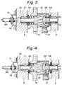
- the output shaft 5 of the electric motor 4 has a gear portion 13, and a reduction gear 14 is arranged between the driven shaft 7 and the gear portion 13 of the output shaft 5.
- This reduction gear 14 comprises a first pair of gears 15 and 16, a second pair of gears 17 and 18, and a third gear 19 fixed on the driven shaft 7.
- the first pair of the gears 15 and 16 is fixed on an intermediate shaft 20 rotatably supported by a pair of bearings 21 and 22, and the second pair of the gears 17 and 18 is fixed on another intermediate shaft 23 rotatably supported by a pair of bearings 24 and 25.
- the intermediate shafts 20 and 23 and the driven shaft 7 are arranged in parallel to the output shaft 5 of the electric motor 4.
- the gear 15 of the first pair is meshed with the gear portion 13 of the output shaft 5, and the gear 16 of the first pair is meshed with the gear 17 of the second pair. Furthermore, the gear 18 of the second pair is meshed with the gear 19 of the driven shaft 7. As illustrated in Figs. 1 and 2, the diameter of the gear portion 13 of the output shaft 5 is smaller than that of the gear 15 of the first pair, and the diameter of the gear 16 of the first pair is smaller than that of the gear 17 of the second pair. Also, the diameter of the gear 18 of the second pair is smaller than that of the gear 19.
- the first stage of a speed reduction operation is carried out between the gear portion 13 of the output shaft 5 and the gear 15 of the first pair; the second stage of a speed reduction operation is carried out between the gear 16 of the first pair and the gear 17 of the second pair; and the third stage of a speed reduction operation is carried out between the gear 17 of the second pair and the gear 19 of the driven shaft 7.
- the output shaft 5, the intermediate shaft 23 of the second pair and the driven shaft 7 are supported by the corresponding bearings 6, 24, 25, 8, 9 such that they cannot move in the axial direction thereof, but the intermediate shaft 20 is supported by the bearings 21, 22 such that it is able to move in the axial direction thereof.
- the gear portion 13, the gear 15 of the first pair, the gear 18 of the second pair and the gear 19 are formed by a spur gear, but the gear 16 of the first pair and the gear 17 of the second pair are formed by a helical gear.
- a thrust bearing 26 is arranged between the outer casing 3 and the spur gear 15, and a compression spring 27 is inserted between the thrust bearing 26 and the enlarged portion of the intermediate shaft 20.
- a thrust bearing 28 is arranged between the inner casing 2 and the helical gear 16, and a compression spring 29 is inserted between the thrust bearing 28 and the helical gear 16.
- these compression springs 27 and 29 are formed such that the compression spring 27 has a stronger spring force than that of the compression spring 29.
- a permanent magnet 30 is fixed to the end face of the intermediate shaft 20, and a sensor MS, which is sensitive to the intensity of the magnetic field produced by the permanent magnet 30, is arranged outside of the outer casing 3.
- the sensor MS is supported by the outer casing 3 via a stay 31, and arranged to face the permanent magnet 30 via the thin walled portion 3a of the outer casing 3.
- the outer casing 3 is made of a non-magnetic material so that the magnetic field produced by the permanent magnet 30 is able to act on the sensor MS.
- a reed contact type sensor having two reed contacts can be used as the sensor MS.
- one of the contacts is normally open and the other is closed when the permanent magnet 30 approaches the sensor 30, and the one of the contacts is normally closed and the other is open when the permanent magnet 30 approaches the sensor MS.
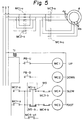
- Figure 5 illustrates a circuit diagram for controlling the electric motor 4, wherein such a reed contact type sensor is used as the sensor MS.
- a transformer Tr having a primary coil connected to the power lines S, T is provided for dropping a voltage.
- An UP push button switch PB-U and an UP relay MC1 are connected in series between the opposed end of the secondary coil of the transfomer Tr, and a DOWN push button switch PB-D and a DOWN relay MC2 are connected in series between the opposed ends of the secondary-coil of the transformer Tr.
- a normally open contact MC2-a of the relay MC2 a normally open contact MS-a of the sensor MS, a normally closed contact MC3-b of a FAST relay MC3, and a SLOW relay MC4 are connected in series between the opposed ends of the secondary coil of the transfomer Tr.
- a normally open contact MC1-a of the UP relay MC1, a normally closed contact MS-b of the sensor MS, a normally closed contact MC4-b of the SLOW relay MC4, and the FAST relay MC3 are connected in series between the opposed end of the secondary coil of the transformer Tr.
- the SLOW relay MC4 has a normally open self-retaining contact MC4-a1 connected at one end between the contact MC2-a and the contact MS-a, and between the contact MC1-a and the contact MS-b, and the other end of this contact MC4-a1 is connected between the contact MS-a and the contact MC3-b.
- the electric motor 4 is a motor in which the rotation speed can be changed by changing the number of poles from two poles to four poles and vice versa.
- the high speed input terminals 4a of the electric motor 4 are connected to the power lines R, S, T via a normally open contact MC3-a of the FAST relay MC3 and via a normally open contact MC1-a of the UP relay MC1 or a normally open contact MC2-a of the DOWN relay MC2.
- the low speed input terminals 4b of the electri motor 4 are connected to the power lines R, S, T via a normally open contact MC4-a of the SLOW relay MC4 and via the normally open contact MC1-a of the UP relay MC1 or the normally open contact MC2-a of the DOWN relay MC2.
- the contact MS-a of the sensor MS remains open, and the contact MS-b of the sensor MS remains closed, as illustrated in Fig. 5.
- the push button switch PB-U since the exciting coil of the UP relay MC1 is energized, the normally open contacts MC1-a are made ON. If the normally open contacts MC1-a are made ON, since the exciting coil of the FAST relay MC3 is energized, the normally open contacts MC3-a are made ON, and the normally closed contact MC3-b is made OFF.
- the high speed input terminals 4a of the electric motor 4 are connected to the power lines R, S, T, the electric motor 4 is rotated at a high speed in a direction causing the hook of the load chain 12 to be moved upward.
- the intermediate shaft 20 is moved toward the sensor MS until the spur gear 15 abuts against the thrust bearing 26.
- the normally open contact MS-a of the sensor MS is made ON, and the normally closed contact MS-b of the sensor MS is made OFF. If the normally closed contact MS-b of the sensor MS is made OFF, since the exciting coil of the FAST relay MC3 is deenergized, the normally open contacts MC3-a are made OFF, and the normally closed contact MC3-b is made ON. At this time, as mentioned above, since the normally open contact MS-a of the sensor MS is ON, the exciting coil of the SLOW relay MC4 is energized.
- the low speed input terminals 4b of the electric motor 4 are connected to the power lines R, S, T, and thus the electric motor 4 is rotated at a low speed in a direction causing the hook of the load chain 12 to be moved upward. Namely, when there is a load on the load chain 12, the lifting speed of the load chain 12 is automatically changed from a high speed to a low speed.
- the exciting coil of the SLOW relay MC4 when the exciting coil of the SLOW relay MC4 is energized, the normally open self-retaining contact MC4-a1 is made ON. Accordingly, even if the intermediate shaft 20 is moved backward after the spur gear 15 has abutted against the thrust bearing 26, and thus the normally open contact MS-a of the sensor MS is made OFF, since the exciting coil of the DOWN relay MC4 remains energized, the electric motor 4 continues to be rotated at a low speed.
- Figure 6 illustrates the case where a Hall element is used as the sensor MS.
- the sensor MS produces an output voltage proportional to the intensity of the magnetic field.
- the output voltage of the sensor MS is applied to the non-inverting terminal of a comparator 40 via an amplifier 41, and the contacts MS-a and MS-b of a relay MSL are controlled by the output voltage of the comparator 40.
- the output voltage of the sensor MS when there is no load on the load chain 12, the output voltage of the sensor MS is at a low level, and at this time, the contact MS-a is OFF and the contact MS-b is ON, as illustrated in Fig. 6.
- the contact MS-a is made ON and the contact of the MS-b is made OFF.
- FIG. 7 illustrates another embodiment of Figs. 1 through 5.
- similar components are indicated by the same reference numerals used in Fig. 1.
- the gear portion 13 of the output shaft 5 and the gear 15 of the first pair of gears are helical gears.
- the direction of the helical teeth of the helical gear portion 13 and the helical gear 15 is predetermined such that, when there is a load on the load chain 12, a force causing the intermediate shaft 20 to be moved toward the sensor MS is imposed on the helical gear 15 by the helical gear portion 13. Accordingly, in this embodiment, when there is a load on the load chain 12, since the intermediate shaft 20 is caused to move toward the sensor MS by the forces imposed by both the helical gear 17 and the helical gear portion 13, a good response of the movement of the intermediate shaft 20 can be obtained.
- Figure 8 illustrates a further embodiment of Figs. 1 through 5.
- the compression spring 29 has a stronger spring force than that of the compression spring 27, and thus when there is no load on the hook of the load chain 12, the spur gear 15 is maintained at a position at which it is in contact with the thrust bearing 26.
- the direction of the helical teeth of the helical gears 16 and 17 is opposite to that of the teeth of the helical gears 16 and 17 illustrated in Figs. 1 through 3, respectively, and thus, when there is a load on the chain load 12, the intermediate shaft 20 is caused to move toward the thrust bearing 28.
- the sensor MS is constructed such that, when the permanent magnet 30 approaches the sensor MS, the contact MS-a (Fig. 5) is made OFF and the contact MS-b (Fig. 5) is made ON, and that, when the permanent magnet MS is remote from the sensor MS, the contact MS-a is made ON and the contact MS-b is made OFF.
- the senor MS is arranged outside of the outer casing 3, and accordingly, an advantage is gained in that the sensor MS will not be damaged by lubricating oil used for lubricating the reduction gear 14.
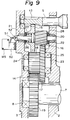
- Figure 9 illustrates a still further embodiment.
- one end of the intermediate shaft 20 projects outward from the outer casing 3. Further, in this embodiment, a limit switch is used as the sensor MS.
- This limit switch MS is fixed to the outer face of the outer casing 3 via a stay 50, and has an operation lever 51 having a tip portion engageable with a ball member 52 screwed into the projecting tip face of the intermediate shaft 20.
- the limit switch MS has two contacts MS-a and MS-b (Fig. 5) actuated by the operation lever 51.
- the intermediate shaft 20 When there is no load on the hook of the load chain 12 (Fig. 1), the intermediate shaft 20 is located at a position illustrated in Fig. 9, and this time the contact MS-a is OFF, and the contact MS-b is ON, as illustrated in Fig. 5. Conversely, if there is a load on the load chain 12, the intermediate shaft 20 is moved toward the limit switch MS, and at this time the contact MS-a is made ON and the contact MS-b is made OFF.
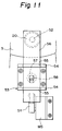
- Figures 10 and 11 illustrate an alternative embodiment of Fig. 9.
- a U-shaped bracket 53 having two arms 54 is fixed to the outer face of the outer casing 3, and two aligned slots 55 are formed on the corresponding arms 54.
- An operation plate 56 is arranged to extend through both of the slots 55, and a compression spring 57 is inserted between the operation plate 56 and the base portion of the bracket 53. The compression spring 57 is retained by the projection 58 of the operation plate 56 and the projection 59 of the bracket 53.
- one end of the operation plate 56 is engaged with the ball member 52 of the intermediate shaft 20, and the other end of the operation plate 56 is engaged with the tip of the operation lever 51 of the limit switch MS.
- the limit switch MS is indirectly actuated by the ball member 52 of the intermediate shaft 5.
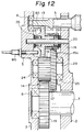
- Figure 12 illustrates a still further embodiment.
- the intermediate shaft 20 is fixed to the inner casing 2 and the outer casing 3, and the gear 15 of the first pair is rotatably inserted to the intermediate shaft 20.
- the helical gear 16 is press-fitted onto the hub portion 15a of the gear 15, so that the helical gear 16 rotates together with the gear 15.
- the gear 15 and the helical gear 16 are located at a position illustrated in Fig. 12, due to the spring force of the compression spring 27.
- the gear 15 and the helical gear 16 are moved toward the thrust bearing 26.
- a Hall element is used as the sensor MS, and an annular permanent magnet plate 60 is embedded in the side wall of the gear 15.
- the detecting tip portion of the sensor MS is arranged inside the outer casing 3, so as to face the annular permanent magnet plate 60.
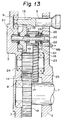
- Figure 13 illustrates a still further embodiment.
- the intermediate shaft 20 is rotatably supported by the bearings 21, 22, and the gear 15 of the first pair is rigidly fixed to the intermediate shaft 20.
- the helical gear 16 is splined onto the intermediate shaft 20, and thus is able to move in the axial direction thereof.
- the helical gear 16 when there is no load on the hook of the load chain 12 (Fig. 1), the helical gear 16 is located at a position illustrated in Fig. 13, due to the spring force of the compression spring 29. Conversely, when there is a load on the load chain 12, the helical gear 16 is moved toward the thrust bearing 28.
- a Hall element is used as the sensor MS, and an annular permanent magnet plate b1 is fixed to the side wall of the helical gear 16.
- the detecting tip portion of the sensor MS is arranged inside the outer casing 3, so as to face the annular permanent magnet plate 61.
- the present invention it is possible to detect whether or not there is a load on the load chain by using the movement of a part of the reduction gear, with which the electric motor is inherently equipped. Accordingly, the cost of manufacturing the hoist can be reduced, and the size of the hoist will not be made larger.
Landscapes
- Engineering & Computer Science (AREA)
- Mechanical Engineering (AREA)
- Connection Of Motors, Electrical Generators, Mechanical Devices, And The Like (AREA)
- Jib Cranes (AREA)
- Gear Transmission (AREA)
- Forklifts And Lifting Vehicles (AREA)
- Load-Engaging Elements For Cranes (AREA)
- Carriers, Traveling Bodies, And Overhead Traveling Cranes (AREA)
- Turning (AREA)
Applications Claiming Priority (4)
| Application Number | Priority Date | Filing Date | Title |
|---|---|---|---|
| JP116550/91 | 1991-04-22 | ||
| JP11655091A JPH0825715B2 (ja) | 1991-04-22 | 1991-04-22 | 無負荷高速運転電動巻上機 |
| JP35133291A JPH0818799B2 (ja) | 1991-12-13 | 1991-12-13 | 無負荷高速運転電動巻上機 |
| JP351332/91 | 1991-12-13 |
Publications (2)
| Publication Number | Publication Date |
|---|---|
| EP0511486A1 true EP0511486A1 (de) | 1992-11-04 |
| EP0511486B1 EP0511486B1 (de) | 1996-07-03 |
Family
ID=26454856
Family Applications (1)
| Application Number | Title | Priority Date | Filing Date |
|---|---|---|---|
| EP92104854A Expired - Lifetime EP0511486B1 (de) | 1991-04-22 | 1992-03-20 | Elektrische Hubvorrichtung |
Country Status (16)
| Country | Link |
|---|---|
| US (1) | US5284325A (de) |
| EP (1) | EP0511486B1 (de) |
| KR (1) | KR0156266B1 (de) |
| CN (1) | CN1044353C (de) |
| BG (1) | BG60909B1 (de) |
| BR (1) | BR9201454A (de) |
| CA (1) | CA2064545C (de) |
| CZ (1) | CZ282137B6 (de) |
| DE (1) | DE69211905T2 (de) |
| DK (1) | DK0511486T3 (de) |
| ES (1) | ES2090391T3 (de) |
| FI (1) | FI101467B1 (de) |
| HU (1) | HU216475B (de) |
| MX (1) | MX9201829A (de) |
| NO (1) | NO307043B1 (de) |
| RU (1) | RU2076062C1 (de) |
Cited By (8)
| Publication number | Priority date | Publication date | Assignee | Title |
|---|---|---|---|---|
| GB2267696A (en) * | 1992-06-12 | 1993-12-15 | Murata Machinery Ltd | Stacker crane. |
| EP0678473A3 (de) * | 1994-04-20 | 1995-12-06 | Stahl R Foerdertech Gmbh | |
| WO1999016698A1 (en) * | 1997-09-30 | 1999-04-08 | Crown Equipment Corporation | Productivity package |
| RU2159733C1 (ru) * | 1999-07-15 | 2000-11-27 | Государственное унитарное предприятие "Производственное объединение "Ульяновский машиностроительный завод" | Механизм подъема тали |
| CN101962162A (zh) * | 2010-11-05 | 2011-02-02 | 八达机电有限公司 | 一种悬挂式电动葫芦 |
| CN107188070A (zh) * | 2017-07-25 | 2017-09-22 | 许利桥 | 一种便携式电动葫芦 |
| US10583539B2 (en) | 2012-04-25 | 2020-03-10 | Milwaukee Electric Tool Corporation | Magnetic drill press |
| US10850954B2 (en) | 2014-02-07 | 2020-12-01 | Konecranes Global Corporation | Hoisting machine arrangement and method for preparing gear thereof |
Families Citing this family (30)
| Publication number | Priority date | Publication date | Assignee | Title |
|---|---|---|---|---|
| JP3295553B2 (ja) * | 1994-10-05 | 2002-06-24 | 三菱電機株式会社 | 可変速装置 |
| US6078263A (en) * | 1996-02-20 | 2000-06-20 | Rs Parts Distributors, Inc. | Method and apparatus for ensuring safe operation of electric overhead door |
| KR100511741B1 (ko) * | 2002-05-08 | 2005-08-31 | 주식회사 만도 | 자동차의 후륜 토우각 제어장치 |
| ITRM20020278A1 (it) * | 2002-05-17 | 2003-11-17 | Giovanni Antonio Vado | Verricello convertibile. |
| US7004456B2 (en) * | 2002-10-03 | 2006-02-28 | Key Energy Services, Inc. | Engine speed limiter for a hoist |
| US6883784B1 (en) * | 2002-10-11 | 2005-04-26 | William L. Sloneker | Boat lift using one-way clutch |
| JP4146714B2 (ja) * | 2002-12-02 | 2008-09-10 | 国産電機株式会社 | 減速機付き電動機 |
| US6767004B1 (en) * | 2003-03-13 | 2004-07-27 | Commander Products Llc | Replacement motorized drive unit for boat lifts |
| JP2006118623A (ja) * | 2004-10-22 | 2006-05-11 | Japan Servo Co Ltd | 歯車装置 |
| US7377485B2 (en) * | 2006-02-28 | 2008-05-27 | Commander Products Llc | Replacement motorized drive unit for boat lifts |
| ES2339961T3 (es) * | 2006-08-31 | 2010-05-27 | ROTZLER GMBH & CO. KG | Torno de cable. |
| US7850145B2 (en) * | 2007-04-05 | 2010-12-14 | Warn Industries, Inc. | Portable pulling tool |
| AU2013206288B2 (en) * | 2007-04-05 | 2016-02-04 | Warn Industries | Pulling tool |
| JP5542319B2 (ja) * | 2008-11-10 | 2014-07-09 | 株式会社日立産機システム | 電気チェーンブロック |
| US7784767B2 (en) * | 2009-01-24 | 2010-08-31 | Nicholas A. Gargaro, III | Boat lift drive |
| FR2973361B1 (fr) * | 2011-04-01 | 2013-05-03 | Siguren Ingenierie | Ensemble comprenant un appareil de securite equipant un dispositif de levage, notamment un treuil, et un systeme d'actionnement de cet appareil |
| US8727661B2 (en) | 2011-04-13 | 2014-05-20 | Portco Automation, Llc | Variable speed boat lift motor controller |
| WO2013036738A1 (en) * | 2011-09-07 | 2013-03-14 | Wilkins Stephen P | Gear reduction assembly and winch including gear reduction assembly |
| CN102534735B (zh) * | 2012-01-13 | 2015-09-23 | 涂其德 | 独立控制小车及电镀设备 |
| JP5394531B2 (ja) * | 2012-04-17 | 2014-01-22 | 株式会社エクセディ | 電気自動車の動力伝達装置 |
| US10040673B1 (en) | 2012-05-28 | 2018-08-07 | Nicholas A. Gargaro, III | Boat lift drive |
| US9463965B2 (en) | 2013-03-13 | 2016-10-11 | Warn Industries, Inc. | Pulling tool |
| US9156665B2 (en) | 2013-03-13 | 2015-10-13 | Warn Industries, Inc. | Pulling tool |
| KR101559117B1 (ko) * | 2015-05-21 | 2015-10-08 | 디와이오토 주식회사 | 차량용 와이퍼 모터 장치 |
| CN105048709A (zh) * | 2015-09-15 | 2015-11-11 | 锐奇控股股份有限公司 | 可自动调节扭矩的电机 |
| CN105293341A (zh) * | 2015-11-18 | 2016-02-03 | 镇江华虹机械有限公司 | 一种电动绞盘 |
| CN208929274U (zh) | 2016-02-01 | 2019-06-04 | 米沃奇电动工具公司 | 磁力钻床的保持力检测 |
| EP3735389A4 (de) * | 2018-01-05 | 2022-02-23 | SafeWorks, LLC | Endlosseilwinde |
| CN110821976B (zh) * | 2019-11-08 | 2021-09-28 | 河海大学常州校区 | 一种传动轴的缓冲连接机构 |
| RU201787U1 (ru) * | 2020-08-18 | 2021-01-13 | ООО Торгово-Производственная Компания "Промышленная безопасность" (ООО ТПК "ПБ") | Тельфер с электрическим приводом |
Citations (9)
| Publication number | Priority date | Publication date | Assignee | Title |
|---|---|---|---|---|
| US2300343A (en) * | 1941-01-24 | 1942-10-27 | Murray G Clay | Hoisting mechanism |
| US2908853A (en) * | 1957-08-23 | 1959-10-13 | Breeze Corp | Winch overload limiting device |
| US3038576A (en) * | 1960-05-24 | 1962-06-12 | Siegler Corp | Torque limiting and overload sensing device |
| US3675751A (en) * | 1970-10-20 | 1972-07-11 | Cavins Co | Torque or motion responsive apparatus |
| DE2714452A1 (de) * | 1976-04-02 | 1977-10-27 | Hitachi Ltd | Hebezeug-ueberlastschutzeinrichtung |
| DE2635612A1 (de) * | 1976-08-07 | 1978-02-09 | Weserhuette Ag Eisenwerk | Ueberwachungseinrichtung fuer hub-, fahr- und schwenkwerke |
| EP0042801A1 (de) * | 1980-06-19 | 1981-12-30 | Etablissements Huchez & Cie | Sicherheitsvorrichtung für Zahnradantrieb |
| FR2547807A1 (fr) * | 1983-06-27 | 1984-12-28 | Huchez & Cie | Dispositif de securite limiteur de couple pour treuil |
| EP0246664A2 (de) * | 1986-05-23 | 1987-11-25 | Kabushiki Kaisha Kito | Stufenloser Geschwindigkeitswechsel für einen elektrischen Kettenflaschenzug |
Family Cites Families (15)
| Publication number | Priority date | Publication date | Assignee | Title |
|---|---|---|---|---|
| US2836085A (en) * | 1955-06-14 | 1958-05-27 | Westinghouse Electric Corp | Two-speed output gearmotor |
| US3285573A (en) * | 1962-08-29 | 1966-11-15 | Hitachi Ltd | Motor block |
| DE1231517B (de) * | 1964-04-25 | 1966-12-29 | Siebeck Metallwerk G M B H | Motorischer Stellantrieb fuer Ventile od. dgl. mit Schneckengetriebe |
| US3564372A (en) * | 1968-11-29 | 1971-02-16 | Black & Decker Mfg Co | Electrical power control means |
| US3784165A (en) * | 1970-11-13 | 1974-01-08 | D Pruitt | Variable speed hoist |
| JPS4831758A (de) * | 1971-08-26 | 1973-04-26 | ||
| US3887855A (en) * | 1973-11-28 | 1975-06-03 | Cleveland Machine Controls | Motor speed modifier control |
| JPS52121257A (en) * | 1976-04-02 | 1977-10-12 | Hitachi Ltd | Overload preventing apparatus for winding machine |
| JPS5319964A (en) * | 1976-08-09 | 1978-02-23 | Toto Kogyo Kk | Wire rod fabricating device |
| US4282776A (en) * | 1979-03-29 | 1981-08-11 | Eller Fritz D | Overload protection for transmission system with planetary-gear train |
| JPS5738294A (en) * | 1980-08-18 | 1982-03-02 | Mitsubishi Electric Corp | Controller for operation of electric winding machine |
| US4428249A (en) * | 1981-12-04 | 1984-01-31 | Pako Corporation | Gear torque sensor apparatus |
| US4555093A (en) * | 1982-10-19 | 1985-11-26 | Ex-Cell-O Corporation | Cable pulling device with force indicator and overload protection |
| US4636962A (en) * | 1983-05-24 | 1987-01-13 | Columbus Mckinnon Corporation | Microprocessor-controlled hoist system |
| NZ220238A (en) * | 1987-05-08 | 1990-08-28 | Maxwell Marine Ltd | Winch with variable speed transmission for yachts |
-
1992
- 1992-03-18 CZ CS92821A patent/CZ282137B6/cs unknown
- 1992-03-18 US US07/853,475 patent/US5284325A/en not_active Expired - Fee Related
- 1992-03-20 DE DE69211905T patent/DE69211905T2/de not_active Expired - Fee Related
- 1992-03-20 EP EP92104854A patent/EP0511486B1/de not_active Expired - Lifetime
- 1992-03-20 ES ES92104854T patent/ES2090391T3/es not_active Expired - Lifetime
- 1992-03-20 DK DK92104854.2T patent/DK0511486T3/da active
- 1992-03-31 CA CA002064545A patent/CA2064545C/en not_active Expired - Fee Related
- 1992-04-20 BG BG96258A patent/BG60909B1/bg unknown
- 1992-04-20 BR BR929201454A patent/BR9201454A/pt not_active IP Right Cessation
- 1992-04-21 KR KR1019920006687A patent/KR0156266B1/ko not_active Expired - Fee Related
- 1992-04-21 FI FI921761A patent/FI101467B1/fi active
- 1992-04-21 RU SU925011381A patent/RU2076062C1/ru active
- 1992-04-21 MX MX9201829A patent/MX9201829A/es not_active IP Right Cessation
- 1992-04-21 NO NO921539A patent/NO307043B1/no not_active IP Right Cessation
- 1992-04-22 CN CN92102891A patent/CN1044353C/zh not_active Expired - Fee Related
- 1992-04-22 HU HU9201305A patent/HU216475B/hu not_active IP Right Cessation
Patent Citations (9)
| Publication number | Priority date | Publication date | Assignee | Title |
|---|---|---|---|---|
| US2300343A (en) * | 1941-01-24 | 1942-10-27 | Murray G Clay | Hoisting mechanism |
| US2908853A (en) * | 1957-08-23 | 1959-10-13 | Breeze Corp | Winch overload limiting device |
| US3038576A (en) * | 1960-05-24 | 1962-06-12 | Siegler Corp | Torque limiting and overload sensing device |
| US3675751A (en) * | 1970-10-20 | 1972-07-11 | Cavins Co | Torque or motion responsive apparatus |
| DE2714452A1 (de) * | 1976-04-02 | 1977-10-27 | Hitachi Ltd | Hebezeug-ueberlastschutzeinrichtung |
| DE2635612A1 (de) * | 1976-08-07 | 1978-02-09 | Weserhuette Ag Eisenwerk | Ueberwachungseinrichtung fuer hub-, fahr- und schwenkwerke |
| EP0042801A1 (de) * | 1980-06-19 | 1981-12-30 | Etablissements Huchez & Cie | Sicherheitsvorrichtung für Zahnradantrieb |
| FR2547807A1 (fr) * | 1983-06-27 | 1984-12-28 | Huchez & Cie | Dispositif de securite limiteur de couple pour treuil |
| EP0246664A2 (de) * | 1986-05-23 | 1987-11-25 | Kabushiki Kaisha Kito | Stufenloser Geschwindigkeitswechsel für einen elektrischen Kettenflaschenzug |
Cited By (10)
| Publication number | Priority date | Publication date | Assignee | Title |
|---|---|---|---|---|
| GB2267696A (en) * | 1992-06-12 | 1993-12-15 | Murata Machinery Ltd | Stacker crane. |
| GB2267696B (en) * | 1992-06-12 | 1995-11-01 | Murata Machinery Ltd | Stacker crane |
| EP0678473A3 (de) * | 1994-04-20 | 1995-12-06 | Stahl R Foerdertech Gmbh | |
| WO1999016698A1 (en) * | 1997-09-30 | 1999-04-08 | Crown Equipment Corporation | Productivity package |
| US6135694A (en) * | 1997-09-30 | 2000-10-24 | Crown Equipment Corporation | Travel and fork lowering speed control based on fork load weight/tilt cylinder operation |
| RU2159733C1 (ru) * | 1999-07-15 | 2000-11-27 | Государственное унитарное предприятие "Производственное объединение "Ульяновский машиностроительный завод" | Механизм подъема тали |
| CN101962162A (zh) * | 2010-11-05 | 2011-02-02 | 八达机电有限公司 | 一种悬挂式电动葫芦 |
| US10583539B2 (en) | 2012-04-25 | 2020-03-10 | Milwaukee Electric Tool Corporation | Magnetic drill press |
| US10850954B2 (en) | 2014-02-07 | 2020-12-01 | Konecranes Global Corporation | Hoisting machine arrangement and method for preparing gear thereof |
| CN107188070A (zh) * | 2017-07-25 | 2017-09-22 | 许利桥 | 一种便携式电动葫芦 |
Also Published As
| Publication number | Publication date |
|---|---|
| DK0511486T3 (da) | 1996-09-30 |
| NO307043B1 (no) | 2000-01-31 |
| FI921761A0 (fi) | 1992-04-21 |
| FI101467B (fi) | 1998-06-30 |
| FI101467B1 (fi) | 1998-06-30 |
| CA2064545C (en) | 2002-02-12 |
| NO921539D0 (no) | 1992-04-21 |
| CN1044353C (zh) | 1999-07-28 |
| BG60909B1 (bg) | 1996-06-28 |
| KR920019661A (ko) | 1992-11-19 |
| EP0511486B1 (de) | 1996-07-03 |
| DE69211905T2 (de) | 1997-02-13 |
| HU216475B (hu) | 1999-06-28 |
| RU2076062C1 (ru) | 1997-03-27 |
| ES2090391T3 (es) | 1996-10-16 |
| US5284325A (en) | 1994-02-08 |
| CN1066042A (zh) | 1992-11-11 |
| NO921539L (no) | 1992-10-23 |
| KR0156266B1 (ko) | 1999-02-18 |
| HUT61244A (en) | 1992-12-28 |
| BG96258A (bg) | 1993-12-24 |
| CS82192A3 (en) | 1992-11-18 |
| BR9201454A (pt) | 1992-12-01 |
| HU9201305D0 (en) | 1992-09-28 |
| MX9201829A (es) | 1993-09-01 |
| FI921761L (fi) | 1992-10-23 |
| CA2064545A1 (en) | 1992-10-23 |
| DE69211905D1 (de) | 1996-08-08 |
| CZ282137B6 (cs) | 1997-05-14 |
Similar Documents
| Publication | Publication Date | Title |
|---|---|---|
| US5284325A (en) | Hoist with load shifted gear, detector, and motor speed changer | |
| FI115966B (fi) | Menetelmä ja laitteisto nostimen nostomoottorin jarrun avautumisen valvontaan | |
| US2704401A (en) | Stock line recorders | |
| US10935090B2 (en) | Brake assembly and servo having the same | |
| WO2011015527A1 (de) | Anordnung zum messen mindestens einer betriebskenngrösse eines hebezeuges | |
| JP3134872B1 (ja) | 巻取装置 | |
| US2274175A (en) | Electric hoist | |
| KR20000062740A (ko) | 호이스트, 특히 소형 호이스트의 권상기용 제어 구동 장치 | |
| KR100491116B1 (ko) | 권상기의 과부하 방지장치 | |
| KR102179553B1 (ko) | 로프형 승강장치 | |
| KR930007068Y1 (ko) | 엘리베이터의 브레이크 제어회로 | |
| KR200213546Y1 (ko) | 전자 클러치가 장착된 셔터 감김 장치 | |
| KR100624553B1 (ko) | 전동식 세탁물 건조대 | |
| JPH0825715B2 (ja) | 無負荷高速運転電動巻上機 | |
| JPS6126314Y2 (de) | ||
| US20240235448A9 (en) | Method of and Apparatus for Controlling Single-Phase Induction Motor, and Electric Chain Block | |
| JPS5931606B2 (ja) | ワイヤ・ロ−プ式水門駆動用電動操作機の制御回路 | |
| JPH05162978A (ja) | 無負荷高速運転電動巻上機 | |
| KR950008053Y1 (ko) | 기계식 과부하 안전장치를 장착한 곤돌라 | |
| JPH07206386A (ja) | 停止位置設定機構およびそれを用いた舞台機構の停止位置設定方法 | |
| EP0557056A1 (de) | Elektrisches Hebezeug | |
| JPH1045356A (ja) | エレベータ | |
| JP2554278B2 (ja) | 回転検出器を用いた変速装置 | |
| US814828A (en) | Safety lowering device. | |
| JPH07122109A (ja) | 昇降装置 |
Legal Events
| Date | Code | Title | Description |
|---|---|---|---|
| PUAI | Public reference made under article 153(3) epc to a published international application that has entered the european phase |
Free format text: ORIGINAL CODE: 0009012 |
|
| AK | Designated contracting states |
Kind code of ref document: A1 Designated state(s): CH DE DK ES FR GB IT LI LU SE |
|
| 17P | Request for examination filed |
Effective date: 19930204 |
|
| 17Q | First examination report despatched |
Effective date: 19940304 |
|
| GRAH | Despatch of communication of intention to grant a patent |
Free format text: ORIGINAL CODE: EPIDOS IGRA |
|
| GRAA | (expected) grant |
Free format text: ORIGINAL CODE: 0009210 |
|
| AK | Designated contracting states |
Kind code of ref document: B1 Designated state(s): CH DE DK ES FR GB IT LI LU SE |
|
| REF | Corresponds to: |
Ref document number: 69211905 Country of ref document: DE Date of ref document: 19960808 |
|
| GRAH | Despatch of communication of intention to grant a patent |
Free format text: ORIGINAL CODE: EPIDOS IGRA |
|
| ITF | It: translation for a ep patent filed | ||
| REG | Reference to a national code |
Ref country code: DK Ref legal event code: T3 |
|
| REG | Reference to a national code |
Ref country code: CH Ref legal event code: NV Representative=s name: BUGNION S.A. |
|
| REG | Reference to a national code |
Ref country code: ES Ref legal event code: FG2A Ref document number: 2090391 Country of ref document: ES Kind code of ref document: T3 |
|
| ET | Fr: translation filed | ||
| REG | Reference to a national code |
Ref country code: ES Ref legal event code: FG2A Ref document number: 2090391 Country of ref document: ES Kind code of ref document: T3 |
|
| PLBE | No opposition filed within time limit |
Free format text: ORIGINAL CODE: 0009261 |
|
| STAA | Information on the status of an ep patent application or granted ep patent |
Free format text: STATUS: NO OPPOSITION FILED WITHIN TIME LIMIT |
|
| 26N | No opposition filed | ||
| PGFP | Annual fee paid to national office [announced via postgrant information from national office to epo] |
Ref country code: FR Payment date: 20010215 Year of fee payment: 10 |
|
| PGFP | Annual fee paid to national office [announced via postgrant information from national office to epo] |
Ref country code: CH Payment date: 20010226 Year of fee payment: 10 |
|
| PGFP | Annual fee paid to national office [announced via postgrant information from national office to epo] |
Ref country code: SE Payment date: 20010307 Year of fee payment: 10 Ref country code: ES Payment date: 20010307 Year of fee payment: 10 |
|
| PGFP | Annual fee paid to national office [announced via postgrant information from national office to epo] |
Ref country code: LU Payment date: 20010313 Year of fee payment: 10 |
|
| PGFP | Annual fee paid to national office [announced via postgrant information from national office to epo] |
Ref country code: GB Payment date: 20010314 Year of fee payment: 10 |
|
| PGFP | Annual fee paid to national office [announced via postgrant information from national office to epo] |
Ref country code: DK Payment date: 20010327 Year of fee payment: 10 |
|
| PGFP | Annual fee paid to national office [announced via postgrant information from national office to epo] |
Ref country code: DE Payment date: 20010430 Year of fee payment: 10 |
|
| REG | Reference to a national code |
Ref country code: GB Ref legal event code: IF02 |
|
| PG25 | Lapsed in a contracting state [announced via postgrant information from national office to epo] |
Ref country code: LU Free format text: LAPSE BECAUSE OF NON-PAYMENT OF DUE FEES Effective date: 20020320 Ref country code: GB Free format text: LAPSE BECAUSE OF NON-PAYMENT OF DUE FEES Effective date: 20020320 |
|
| PG25 | Lapsed in a contracting state [announced via postgrant information from national office to epo] |
Ref country code: SE Free format text: LAPSE BECAUSE OF NON-PAYMENT OF DUE FEES Effective date: 20020321 Ref country code: ES Free format text: LAPSE BECAUSE OF NON-PAYMENT OF DUE FEES Effective date: 20020321 |
|
| PG25 | Lapsed in a contracting state [announced via postgrant information from national office to epo] |
Ref country code: LI Free format text: LAPSE BECAUSE OF NON-PAYMENT OF DUE FEES Effective date: 20020331 Ref country code: CH Free format text: LAPSE BECAUSE OF NON-PAYMENT OF DUE FEES Effective date: 20020331 |
|
| PG25 | Lapsed in a contracting state [announced via postgrant information from national office to epo] |
Ref country code: DK Free format text: LAPSE BECAUSE OF NON-PAYMENT OF DUE FEES Effective date: 20020402 |
|
| PG25 | Lapsed in a contracting state [announced via postgrant information from national office to epo] |
Ref country code: DE Free format text: LAPSE BECAUSE OF NON-PAYMENT OF DUE FEES Effective date: 20021001 |
|
| EUG | Se: european patent has lapsed |
Ref document number: 92104854.2 |
|
| GBPC | Gb: european patent ceased through non-payment of renewal fee |
Effective date: 20020320 |
|
| REG | Reference to a national code |
Ref country code: CH Ref legal event code: PL |
|
| REG | Reference to a national code |
Ref country code: DK Ref legal event code: EBP |
|
| PG25 | Lapsed in a contracting state [announced via postgrant information from national office to epo] |
Ref country code: FR Free format text: LAPSE BECAUSE OF NON-PAYMENT OF DUE FEES Effective date: 20021129 |
|
| REG | Reference to a national code |
Ref country code: FR Ref legal event code: ST |
|
| REG | Reference to a national code |
Ref country code: ES Ref legal event code: FD2A Effective date: 20030410 |
|
| PG25 | Lapsed in a contracting state [announced via postgrant information from national office to epo] |
Ref country code: IT Free format text: LAPSE BECAUSE OF NON-PAYMENT OF DUE FEES;WARNING: LAPSES OF ITALIAN PATENTS WITH EFFECTIVE DATE BEFORE 2007 MAY HAVE OCCURRED AT ANY TIME BEFORE 2007. THE CORRECT EFFECTIVE DATE MAY BE DIFFERENT FROM THE ONE RECORDED. Effective date: 20050320 |